1
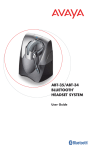
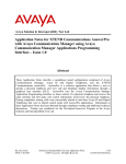
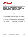
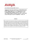
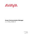
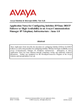
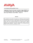
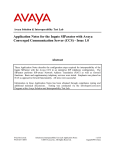
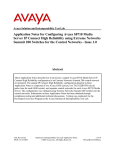
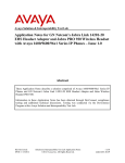
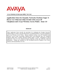
Avaya Solution & Interoperability Test Lab
Application Notes for Mirage Networks CounterPoint in an
Avaya IP Telephony Infrastructure – Issue 1.0
Abstract
These Application Notes describe a configuration where the Mirage Networks CounterPoint
network access control appliance protects the subnets where an Avaya Media Server, an Avaya
Media Gateway, and Avaya IP Telephones reside against rapidly propagating threats. During
compliance testing, the CounterPoint detected basic ping and port scans that often precede
threats on the protected subnets, and mitigated basic Denial of Service (DoS) attacks.
Information in these Application Notes has been obtained through compliance testing and
additional technical discussions. Testing was conducted via the DeveloperConnection
Program at the Avaya Solution and Interoperability Test Lab.
RL; Reviewed:
SPOC 9/23/2005
Solution & Interoperability Test Lab Application Notes
©2005 Avaya Inc. All Rights Reserved.
1 of 17
MirageCP.doc
1. Introduction
These Application Notes describe a configuration where the Mirage Networks CounterPoint
appliance is deployed in an Avaya IP telephony infrastructure. CounterPoint is a network access
control appliance that is designed to protect the internal corporate network against rapidly
propagating threats that originate inside the network. CounterPoint operates within the network
interior, and is complementary to perimeter security solutions.
CounterPoint uses pre-defined and configurable rules in monitoring the network for potential
threats. Once a threat is identified, CounterPoint mitigates the threat by “cloaking”, where
CounterPoint logically inserts itself in the path between the attacker and the target. Specifically,
CounterPoint redirects the attacker communications streams to itself by changing the ARP tables
in the attacker and/or target device. CounterPoint can then selectively filter out malicious
packets and forward the rest to the target. CounterPoint can also be configured to send alerts via
e-mail (SMTP), SNMP, and Syslog when threats are identified.
Figure 1 illustrates a sample configuration consisting of an Avaya S8710 Media Server, an
Avaya G650 Media Gateway, Avaya IP Telephones, an Avaya P333T-PWR Power over Ethernet
Stackable Switch, a Cisco Catalyst 3560 Series switch, an “Attacker” PC, and a Mirage
Networks CounterPoint C-245. Avaya Communication Manager runs on the S8710 Media
Server, though the solution described herein is also extensible to other Avaya Media Servers and
Media Gateways. The S8710 Media Server and G650 Media Gateway reside on VLAN 100 and
are connected to the P333T-PWR, which in turn connects to the Catalyst 3560 via an 802.1q
trunk. The IP Telephones reside on VLAN 53 and the “Attacker” PC resides on VLAN 51.
The CounterPoint C-245 connects to two ports on the Catalyst 3560. The VLANs to be
protected (VLANs 53 and 100) are also assigned to the two ports. VLAN 51 could not be
protected for reasons discussed in Section 3. The protected VLANs are mirrored to one of the
two Catalyst 3560 ports (the “Reader” port”), allowing the CounterPoint C-245 to monitor
unicast and broadcast traffic on the protected VLANs. The other port (the “Writer” port) allows
the CounterPoint C-245 to transmit ARP messages onto the protected VLANs and perform
cloaking.
RL; Reviewed:
SPOC 9/23/2005
Solution & Interoperability Test Lab Application Notes
©2005 Avaya Inc. All Rights Reserved.
2 of 17
MirageCP.doc
COM PACT
COM PACT
Avaya S8710
Media Server
Avaya G650
Media Gateway
VLAN 100: 192.45.100.0/24
Avaya P333T-PWR Power over Ethernet
Stackable Switch
Port 1/24
VLAN 100
802.1q Trunk
VLAN Mirror Port 0/22
(VLANs 53, 100)
Port 0/23
Catalyst 3560
1
VLAN 51: 192.45.51.0/24
2
3
4
5
6
7
8
9
10
11
12
13
14
15
16
17
18
19
20
21
22
23
SERIES
PoE-24
24
1X
11X
13X
23X
2X
12X
14X
24X
SYST
RPS
STAT
DUPLX
SPEED
POE
1
2
MODE
Cisco Catalyst 3560 Switch
VLAN Trunk Port
0/21 (VLANs 53,
100)
VLAN 53: 192.45.53.0/24
“Writer”
Port
“Attacker” PC
“Reader”
Port
.…..
Avaya 4600 Series
IP Telephones
Mirage Networks
CounterPoint C-245
Figure 1: Sample configuration.
RL; Reviewed:
SPOC 9/23/2005
Solution & Interoperability Test Lab Application Notes
©2005 Avaya Inc. All Rights Reserved.
3 of 17
MirageCP.doc
2. Equipment and Software Validated
The following equipment and software/firmware were used for the sample configuration
provided:
Equipment
Avaya S8710 Media Server
Avaya G650 Media Gateway
TN2312BP IP Server Interface
TN799DP C-LAN Interface
TN2302AP IP Media Processor
Avaya 4600 Series IP Telephones
Avaya P333T-PWR Power over Ethernet
Stackable Switch
Mirage Networks CounterPoint C-245
Cisco Catalyst 3560 Series Switch
PC
RL; Reviewed:
SPOC 9/23/2005
Software/Firmware
3.0 (340.3)
21
15
104
1.8.2 (4602SW)
2.2.3 (4610SW)
2.2.3 (4620SW)
2.5 (4625SW)
2.0.2 (4630SW)
4.0.17
2.2 Build 4583
IOS 12.1
Red Hat Linux ES 3
Solution & Interoperability Test Lab Application Notes
©2005 Avaya Inc. All Rights Reserved.
4 of 17
MirageCP.doc
3. Configure Mirage Networks CounterPoint C-245
This section describes the steps for configuring the Mirage Networks CounterPoint C-245 to
protect the subnets (VLANs 53 and 100 in the sample configuration) where the S8710 Media
Server, G650 Media Gateway, and IP telephones reside. The subnet (VLAN 51) where the
attacker PC resides cannot be protected due to the VLAN mirror function of the Cisco Catalyst
3560. Specifically, when the Catalyst 3560 receives untagged frames from VLAN 51 endpoints,
including the attacker PC, the Catalyst 3560 copies the untagged frames to the mirror port
without applying the VLAN 51 tag. Without the VLAN tag, the CounterPoint C-245 cannot
determine what subnet the frames belong to, and thus has no “visibility” into VLAN 51 and
cannot protect the subnet. The CounterPoint C-245 does have visibility into VLAN 53 because
the IP telephones transmit/receive tagged frames, and into VLAN 100 due to the configuration of
an 802.1q trunk between the Catalyst C3650 and Avaya P333T-PWR (see Sections 4 and 5).
Contact Mirage Networks for guidance and instruction on CounterPoint rules configuration.
Step
Description
1. Launch the CounterPoint Manager application and log in with the appropriate credentials.
2.
Select the Edit Config tab and expand the Network Topology tree to the Segments level.
Select a QTag (VLAN) and click on the “Edit Name” icon.
RL; Reviewed:
SPOC 9/23/2005
Solution & Interoperability Test Lab Application Notes
©2005 Avaya Inc. All Rights Reserved.
5 of 17
MirageCP.doc
Step
Description
3. Assign a descriptive name and click on “OK”.
4.
Select the Subnets tab and click on the “+” icon.
5.
Enter the subnet information for this VLAN, and check the “Add Protected Range” checkbox
to protect the entire subnet*. Click on “OK”.
* To protect specific ranges within the subnet, uncheck the “Add Protected Range” checkbox
and configure the ranges in the Protected Subnets tab (not described in these Application
Notes)
6.
Select the Gateway tab and click on the “+” icon.
RL; Reviewed:
SPOC 9/23/2005
Solution & Interoperability Test Lab Application Notes
©2005 Avaya Inc. All Rights Reserved.
6 of 17
MirageCP.doc
Step
Description
7. Enter the default gateway of the subnet and click on “OK”.
8.
Select the Deception tab. Set Deception Mode to “On”.
RL; Reviewed:
SPOC 9/23/2005
Solution & Interoperability Test Lab Application Notes
©2005 Avaya Inc. All Rights Reserved.
7 of 17
MirageCP.doc
Step
Description
9. Select the Cloak tab. The default values may be used.
RL; Reviewed:
SPOC 9/23/2005
Solution & Interoperability Test Lab Application Notes
©2005 Avaya Inc. All Rights Reserved.
8 of 17
MirageCP.doc
Step
Description
10. Select the Advanced tab. Set MAC Validation to “On”.
Note: MAC validation is required in order to detect spoofing.
RL; Reviewed:
SPOC 9/23/2005
Solution & Interoperability Test Lab Application Notes
©2005 Avaya Inc. All Rights Reserved.
9 of 17
MirageCP.doc
Step
11. Click on the “Edit Segment IP” icon.
Description
12. Assign an IP Address to the CounterPoint C-245 on this VLAN and click on “OK”.
RL; Reviewed:
SPOC 9/23/2005
Solution & Interoperability Test Lab Application Notes
©2005 Avaya Inc. All Rights Reserved.
10 of 17
MirageCP.doc
Step
Description
13. Expand the VLAN tree and select one of the two interfaces. These two VLAN interfaces reside
on the two ports connected to the Catalyst 3560. Click on “Enable”. Repeat this step for the
other interface.
RL; Reviewed:
SPOC 9/23/2005
Solution & Interoperability Test Lab Application Notes
©2005 Avaya Inc. All Rights Reserved.
11 of 17
MirageCP.doc
Step
Description
14. Select one of the interfaces and click on the “Pair” button.
15. Select the other interface from the pull-down list and click on “OK”.
RL; Reviewed:
SPOC 9/23/2005
Solution & Interoperability Test Lab Application Notes
©2005 Avaya Inc. All Rights Reserved.
12 of 17
MirageCP.doc
Step
Description
16. Click on the “Configure Changes” icon on the bottom left of the CounterPoint Manager main
window.
17. Click on “Save” and then “Close”.
RL; Reviewed:
SPOC 9/23/2005
Solution & Interoperability Test Lab Application Notes
©2005 Avaya Inc. All Rights Reserved.
13 of 17
MirageCP.doc
Step
Description
18. Repeat Step 2 – 17 as necessary to protect other VLANs. In this configuration, the steps were
repeated for VLAN 53.
4. Configure Cisco Catalyst 3560
This section describes the steps on the Cisco Catalyst 3560 for configuring the VLAN mirror, the
two ports connected to the Mirage Networks CounterPoint C-245, and the port connected to the
Avaya P333T-PWR. The steps assumed that the VLANs and routing among VLANs have
already been configured on the Catalyst 3560.
Step
Description
1. From the Catalyst 3560 Command Line Interface (CLI), assign the protected VLANs (53 and
100 in the sample configuration) to the two ports connected to the CounterPoint C-245, and
configure the ports as trunk ports with 802.1q encapsulation.
interface FastEthernet0/21
switchport trunk encapsulation dot1q
switchport trunk allowed vlan 53,100
switchport mode trunk
no ip address
no mdix auto
!
interface FastEthernet0/22
switchport trunk encapsulation dot1q
switchport trunk allowed vlan 53,100
switchport mode trunk
no ip address
no mdix auto
2.
Configure a monitor session to mirror all VLAN traffic from the protected VLANs to the port in
Step 1 connected to the “Reader” port on the CounterPoint C-245.
monitor session 1 source vlan 53 , 100
monitor session 1 destination interface Fa0/22 encapsulation replicate
3.
Assign VLAN 100 to the port connected to the Avaya P333T-PWR, and configure the port as a
trunk port with 802.1q encapsulation.
interface FastEthernet0/23
switchport trunk encapsulation dot1q
switchport trunk allowed vlan 100
switchport mode trunk
no ip address
no mdix auto
RL; Reviewed:
SPOC 9/23/2005
Solution & Interoperability Test Lab Application Notes
©2005 Avaya Inc. All Rights Reserved.
14 of 17
MirageCP.doc
5. Configure Avaya P333T-PWR
From the Avaya P333T-PWR CLI, assign VLAN 100 to all ports, including the port connected
to the Cisco Catalyst 3560, and configure the port as an 802.1q trunk port.
set port vlan 100 1/1-24
set trunk 1/24 dot1q
6. Interoperability Compliance Testing
The interoperability compliance testing focused on verifying that the Mirage Networks
CounterPoint C-245 detected basic ping and port scans, and mitigated basic Denial of Service
(DoS) attacks.
6.1. General Test Approach
The general approach was to launch ping scans on the protected VLANs, and port scans and
basic DoS attacks on the C-LAN and Media Processor boards on the Avaya G650 Media
Gateway, as well as the Avaya IP Telephones. The main objectives were to verify that:
•
•
•
•
•
The CounterPoint C-245 correctly detects basic ping, TCP SYN, and UDP scans on
protected subnets.
The CounterPoint C-245 correctly detects basic DoS attacks, such as ping, TCP
SYN/FIN, and UDP floods, against the C-LAN and Media Processor boards on the
Avaya G650 Media Gateway, and the Avaya IP Telephones.
The CounterPoint C-245 cloaks (mitigates) the basic DoS attacks where possible (see
Test Results section).
Avaya IP Telephones on the protected subnets successfully establish and maintain calls
during the basic scan and DoS attack activity.
Avaya IP Telephones on the protected subnets successfully established and maintain
calls when there is no scan or DoS attack activity.
6.2. Test Results
The test objectives of Section 6.1 were verified. The CounterPoint C-245 was able to detect the
basic ping and port scans, and mitigate basic non-spoofed DoS attacks generated by the attacker
PC. In DoS attacks where the source IP addresses were spoofed VLAN 53 and VLAN 100 IP
addresses, the CounterPoint C-245 could not cloak the source (attacker PC) because it did not
know the MAC address of the source (recall from Section 3 that the CounterPoint C-245 did not
have visibility into VLAN 51). The CounterPoint C-245 also did not cloak the target because
redirecting packets intended for the target and filtering based on the source IP address would also
filter out legitimate packets from the spoofed source.
RL; Reviewed:
SPOC 9/23/2005
Solution & Interoperability Test Lab Application Notes
©2005 Avaya Inc. All Rights Reserved.
15 of 17
MirageCP.doc
7. Verification Steps
The following steps may be used to verify the configuration:
•
•
•
From the attacker PC, run ping scans on the protected subnets and verify that the
CounterPoint C-245 correctly reports the scans.
From the attacker PC, run port scans on specific targets in the protected subnets and
verify that the CounterPoint C-245 correctly reports the scans.
From the attacker PC, send basic ping and port floods to specific targets in the protected
subnets. Verify that one or more CounterPoint rules are triggered and the CounterPoint
C-245 correctly reports the attack. If “Cloaked” is reported as the response(s) for the
triggered rule(s), verify that the ARP tables of the source, target, and/or Catalyst 3650
have been changed such that the attack communication streams are redirected to the
CounterPoint C-245. If “Tracked” is reported as the response(s) for the triggered rule(s),
then perform a manual cloak operation and verify the ARP tables as per above.
8. Support
For technical support on the Mirage Networks CounterPoint C-245, consult the support pages at
http://miragenetworks.com/support.html or contact Mirage Networks customer support at:
•
•
Phone: 866.869.6767
E-mail: [email protected]
9. Conclusion
These Application Notes described a configuration where the Mirage Networks CounterPoint
network access control appliance protects the subnets where an Avaya Media Server, an Avaya
Media Gateway, and Avaya IP Telephones reside against rapidly propagating threats. During
compliance testing, the CounterPoint detected basic ping and port scans that often precede
threats on the protected subnets, and mitigated basic Denial of Service (DoS) attacks against the
aforementioned Avaya IP telephony endpoints.
10. Additional References
Product documentation for Avaya products may be found at http://support.avaya.com.
Product information for Mirage Networks products may be found at
http://miragenetworks.com/p_index.html.
RL; Reviewed:
SPOC 9/23/2005
Solution & Interoperability Test Lab Application Notes
©2005 Avaya Inc. All Rights Reserved.
16 of 17
MirageCP.doc
©2005 Avaya Inc. All Rights Reserved.
Avaya and the Avaya Logo are trademarks of Avaya Inc. All trademarks identified by ® and ™
are registered trademarks or trademarks, respectively, of Avaya Inc. All other trademarks are the
property of their respective owners. The information provided in these Application Notes is
subject to change without notice. The configurations, technical data, and recommendations
provided in these Application Notes are believed to be accurate and dependable, but are
presented without express or implied warranty. Users are responsible for their application of any
products specified in these Application Notes.
Please e-mail any questions or comments pertaining to these Application Notes along with the
full title name and filename, located in the lower right corner, directly to the Avaya
DeveloperConnection Program at [email protected].
RL; Reviewed:
SPOC 9/23/2005
Solution & Interoperability Test Lab Application Notes
©2005 Avaya Inc. All Rights Reserved.
17 of 17
MirageCP.doc