1
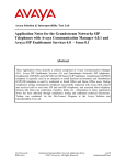
Avaya Solution & Interoperability Test Lab
Application Notes for Configuring compressed Real Time
Protocol over Multi-Link Point-to-Point Protocol between
Juniper Networks J4300 and M7i routers to Support an Avaya
IP Telephony Infrastructure – Issue 1.0
Abstract
These Application Notes describe the steps for configuring Juniper Networks J4300 and M7i
routers to use compressed RTP (cRTP) over a Multi-Link Point-to-Point Protocol (MLPPP)
connection to support an Avaya IP Telephony Infrastructure consisting of Avaya
Communication Manager and Avaya IP Telephones. The Juniper Networks routers will
perform header compression for all RTP traffic traversing over the MLPPP connection to
minimize overhead used by the RTP packets thus increasing available bandwidth, and load
distribution across the multi-link bundle for increase bandwidth and resiliency.
AL; Reviewed:
SPOC 2/12/2007
Solution & Interoperability Test Lab Application Notes
©2007 Avaya Inc. All Rights Reserved.
1 of 21
J&M-cRTP-MLPPP.doc
1. Introduction
Real Time Protocol (RTP) packets generated by Voice over IP (VoIP) telephony are typically small
in size ranging in tens of bytes per packet. IP (20 bytes) and UDP (8 bytes) headers are then added
onto each packet before transmission. Because of the relative small packet size of RTP packet, the
IP and UDP headers are all overhead. For RTP packets that traverses a Wide Area Network (WAN)
with limited bandwidth, these headers represents an opportunity for bandwidth saving that could
otherwise be use for other traffic or additional VoIP calls. This is the main idea behind the use of
cRTP.
It is most common to use the G.729 codec for calls across a low speed link due to its lower
bandwidth requirement, but either G.711 or G.729 codecs can benefit from cRTP. Both G.711 and
G.729 codec were exercised during compliance testing.
In addition, the Juniper J4300 and M7i router also has the ability to distribute VoIP traffic across all
members on a per flow basis. The Juniper routers accomplished per flow load distribution through
the examination of the 5tuples (Source/Destination IP, Source/Destination Port, and protocol) in
each packet. Since these 5 pieces of information are the same for any given call flow, all rtp packets
for a particular call will always be distributed onto the same multilink member. This is an important
feature as members within a multilink bundle may be from different Service Provider and the links
may have varying delay characteristic. Therefore, the ability of performing per flow load balancing
can help minimize jitter in VoIP application.
Figure 1, shows the sample network used in these Application Notes. Two separate IP networks,
one in each location are connected together by a pair of Juniper Networks routers over a MLPPP
connection. Each location contains an Avaya Media Server, an Avaya Media Gateway, and Avaya
IP Telephones. A dial plan and an H.323 trunk configured between the two Avaya Communication
Managers allow calls to be routed between the two systems. Both the Juniper Networks M7i and
J4300 routers are configured to perform RTP header compression for all RTP packets traversing
over the PPP connection. Both routers are configured to prioritize VoIP traffic based on DiffServ
Code Point (DSCP) information encoded in each VoIP packet. Bandwidth allocation was set on all
interfaces shown to guarantee necessary bandwidth is reserved for VoIP traffic in the event of
network congestion. Both Juniper routers will statistically distribute the call flows across all
members of the MLPPP bundle. The combination of these elements provides the necessary Quality
of Service for VoIP traffic traversing over the WAN connection.
AL; Reviewed:
SPOC 2/12/2007
Solution & Interoperability Test Lab Application Notes
©2007 Avaya Inc. All Rights Reserved.
2 of 21
J&M-cRTP-MLPPP.doc
2. Configuration
Figure 1 illustrates the configuration used in these Application Notes. Telephones with range
number 3xxxx are registered with the Avaya S8300 Media Server on the right side of the figure, and
telephones with extension range 2xxxx are registered with the Avaya S8500 Media Server on the left
side of the figure. An H.323 IP trunk was used to route calls between the two Avaya Media Servers.
Note that extensions from both Avaya Communication Manager systems are located in each
location. This is done to verify the Avaya IP Telephones can register and place call successfully
through a cRTP enabled WAN connection.
Figure 1: Sample Network Configuration
AL; Reviewed:
SPOC 2/12/2007
Solution & Interoperability Test Lab Application Notes
©2007 Avaya Inc. All Rights Reserved.
3 of 21
J&M-cRTP-MLPPP.doc
3. Equipment and Software Validated
The following equipment and software/firmware were used for the sample configuration:
Equipment
Avaya S8300 Media Server with
G350 Media Gateway
Avaya S8500 Media Server
Avaya G650 Media Gateway
TN2312BP IPSI
TN799DP C-LAN
TN2302AP IP MedPro
Analog telephone
Avaya 6408D digital Telephone
Avaya 4602SW IP Telephone (H.323)
Avaya 4610SW IP Telephone (H.323)
Avaya 4620SW IP Telephone (H.323)
Avaya IP Softphone
Juniper Networks J4300 router
Juniper Networks M7i router
AL; Reviewed:
SPOC 2/12/2007
Software/Firmware
Avaya Communication Manager R3.1.2
(R013x.01.2.632.1)
Avaya Communication Manager R3.1.2
(R013x.01.2.632.1)
HW03 FW 22
HW01 FW 16
HW18 FW 108
N/A
N/A
R2.3 – Application (a10d01b2_3.bin)
R2.6 – Application (a10d01b2_6.bin)
R.2.6 – Application (a20d01b2_6.bin)
R5.24.8
JUNOS 8.1R1.5
JUNOS 8.1R1.5
Solution & Interoperability Test Lab Application Notes
©2007 Avaya Inc. All Rights Reserved.
4 of 21
J&M-cRTP-MLPPP.doc
4. Avaya Communication Manager
There is no unique configuration required in Avaya Communication Manager to support compressed
RTP (cRTP) or any feature mentioned in this document. For detailed information on the Installation,
Maintenance, and Configuration of Avaya Communication Manager, please consult reference [1],
[2], and [3].
Step
Description
Below is the output from the display ip-network-region command showing the
1.
MEDIA PARAMETERS, and DIFFSERV/TOS PARAMETERS information
configured in Avaya Communication Manager. All traffic used in the sample network is
configured for network region 1.
The Call Control PHB Value of 34 is equivalent to 100010 in binary.
The Audio PHB Value of 46 is equivalent to 101110 in binary.
The MEDIA PARAMETERS, and DIFFSERV/TOS PARAMETERS information
will be needed in later sections when configuring the routers.
display ip-network-region 1
Page
1 of
19
IP NETWORK REGION
Region: 1
Location:
Authoritative Domain:
Name:
MEDIA PARAMETERS
Intra-region IP-IP Direct Audio: yes
Codec Set: 1
Inter-region IP-IP Direct Audio: yes
UDP Port Min: 2048
IP Audio Hairpinning? n
UDP Port Max: 3029
DIFFSERV/TOS PARAMETERS
RTCP Reporting Enabled? y
Call Control PHB Value: 34
RTCP MONITOR SERVER PARAMETERS
Audio PHB Value: 46
Use Default Server Parameters? y
Video PHB Value: 26
802.1P/Q PARAMETERS
Call Control 802.1p Priority: 6
Audio 802.1p Priority: 6
Video 802.1p Priority: 5
AUDIO RESOURCE RESERVATION PARAMETERS
H.323 IP ENDPOINTS
RSVP Enabled? n
H.323 Link Bounce Recovery? y
Idle Traffic Interval (sec): 20
Keep-Alive Interval (sec): 5
Keep-Alive Count: 5
AL; Reviewed:
SPOC 2/12/2007
Solution & Interoperability Test Lab Application Notes
©2007 Avaya Inc. All Rights Reserved.
5 of 21
J&M-cRTP-MLPPP.doc
5. Configure the Juniper Networks Routers
The following sections describe the steps for configuring the different Juniper Networks routers in
the sample configuration. Unless otherwise specified, all router configurations are based on Juniper
Networks recommendation.
5.1. Configure the Juniper Networks J4300 Router
This section shows the necessary steps in configuring the Juniper J4300 router as shown in the
sample network. The following steps use the Command Line Interface (CLI) offered by the J4300
router.
Step
Description
Connect to the J4300. Log in using the appropriate Login ID and Password.
1.
login:
Password:
The following prompt will appears after successful log in.
interop@J4300>
2.
Enter configuration mode by typing in edit at the prompt.
interop@J4300> edit
interop@J4300#
AL; Reviewed:
SPOC 2/12/2007
Solution & Interoperability Test Lab Application Notes
©2007 Avaya Inc. All Rights Reserved.
6 of 21
J&M-cRTP-MLPPP.doc
Step
Description
Configure the code-point-aliases and classifier for Avaya VoIP traffic.
3.
•
•
•
The alias helps identify the binary dscp setting.
The sample network uses the name “avaya-rtp” to denote dscp binary bit 101110
for media traffic. This is equivalent to the decimal Audio PHB Value of 46 set
in Avaya Communication Manager for RTP Media in Section 4, Step 1.
The sample network uses the name “avaya-sig” to denote dscp binary bit 100010
for signaling traffic. This is equivalent to the decimal Call Control PHB Value
of 34 set in Avaya Communication Manager for signaling in Section 4, Step 1.
interop@J4300#
interop@J4300#
interop@J4300#
interop@J4300#
•
•
•
edit class-of-service code-point-aliases
set dscp avaya-rtp 101110
set dscp avaya-sig 100010
exit
Define a classifier called “Avaya-voip”.
The classifier “Avaya-voip” defines the forwarding characteristic used by the
router based on traffic type.
The sample configuration is configured to use expedited-forwarding with low
loss-priority for “avaya-rtp”, and assured-forwarding with low loss-priority for
“avaya-sig” to ensure proper Quality of Service (QoS) priority is assigned to
voice traffic.
interop@J4300# edit class-of-service classifiers
interop@J4300# edit dscp Avaya-voip
interop@J4300# set forwarding-class expedited-forwarding loss-priority
low code-points avaya-rtp
interop@J4300# set forwarding-class assured-forwarding loss-priority
low code-points avaya-sig
interop@J4300# exit
AL; Reviewed:
SPOC 2/12/2007
Solution & Interoperability Test Lab Application Notes
©2007 Avaya Inc. All Rights Reserved.
7 of 21
J&M-cRTP-MLPPP.doc
Step
Description
Configure the scheduler to specify how much bandwidth to allocate for each type of
4.
traffic queue.
•
The sample configuration defines a scheduler-maps called “voip”, and assigns a
name for each of the 4 queues types.
interop@J4300#
interop@J4300#
interop@J4300#
interop@J4300#
edit class-of-service scheduler-maps
edit voip
set forwarding-class best-effort scheduler be-sched
set forwarding-class expedited-forwarding scheduler efsched
interop@J4300# set forwarding-class assured-forwarding scheduler afsched
interop@J4300# set forwarding-class network-control scheduler nc-sched
interop@J4300# exit
•
Use the scheduler to define the percentage of bandwidth allocation to each traffic
queue type. These allocations are for testing purpose only. The actual
bandwidth allocation should depend upon actual requirement.
interop@J4300#
interop@J4300#
interop@J4300#
interop@J4300#
interop@J4300#
interop@J4300#
interop@J4300#
interop@J4300#
interop@J4300#
interop@J4300#
interop@J4300#
interop@J4300#
interop@J4300#
interop@J4300#
interop@J4300#
interop@J4300#
interop@J4300#
interop@J4300#
interop@J4300#
interop@J4300#
interop@J4300#
AL; Reviewed:
SPOC 2/12/2007
edit class-of-service schedulers
edit be-sched
set transmit-rate percent 10
set buffer-size percent 10
set priority low
exit
edit ef-sched
set transmit-rate percent 80
set buffer-size percent 80
set priority high
exit
edit af-sched
set transmit-rate percent 5
set buffer-size percent 5
set priority high
exit
edit nc-sched
set transmit-rate percent 5
set buffer-size percent 5
set priority high
exit
Solution & Interoperability Test Lab Application Notes
©2007 Avaya Inc. All Rights Reserved.
8 of 21
J&M-cRTP-MLPPP.doc
Step
Description
Assign the scheduler-map to each interface.
5.
•
Configure each interface with scheduler-map voip using the classifier defined
above.
interop@J4300#
interop@J4300#
interop@J4300#
interop@J4300#
interop@J4300#
interop@J4300#
interop@J4300#
interop@J4300#
interop@J4300#
interop@J4300#
interop@J4300#
interop@J4300#
interop@J4300#
interop@J4300#
interop@J4300#
interop@J4300#
AL; Reviewed:
SPOC 2/12/2007
edit class-of-service interfaces fe-0/0/1
set unit 0 scheduler-map voip
set unit 0 classifiers dscp avaya-voip
exit
edit class-of-service interfaces ls-0/0/0
set unit 0 scheduler-map voip
set unit 0 classifiers dscp avaya-voip
exit
edit class-of-service interfaces t1-2/0/0
set unit 0 scheduler-map voip
set unit 0 classifiers dscp avaya-voip
exit
edit class-of-service interfaces t1-2/0/1
set unit 0 scheduler-map voip
set unit 0 classifiers dscp avaya-voip
exit
Solution & Interoperability Test Lab Application Notes
©2007 Avaya Inc. All Rights Reserved.
9 of 21
J&M-cRTP-MLPPP.doc
Step
Description
Configure the Ethernet and T1 interfaces.
6.
•
•
Configure the Ethernet interface to use the scheduler.
Assign an IP address to the interface.
interop@J4300#
interop@J4300#
interop@J4300#
interop@J4300#
•
•
•
•
Configure the logical interface for the WAN connection to use the scheduler.
Limit packet fragmentation of packet at 128 bytes.
Assigned an IP address to the interface.
Specify the RTP traffic to be compressed. The sample configuration defines
RTP traffic with port range 2048 to 3029 to be compressed. This port range
needs to match to UDP Port Min and UDP Port Max configured in Avaya
Communication Manager in Section 4, Step 1.
interop@J4300#
interop@J4300#
interop@J4300#
interop@J4300#
interop@J4300#
interop@J4300#
•
•
•
edit int ls-0/0/0
set per-unit-scheduler
set unit 0 fragment-threshold 128
set unit 0 compression rtp port min 2048 max 3029
set unit 0 family inet 192.168.1.1/30
exit
Configure the T1 interfaces to use the scheduler.
Configure the T1 interfaces timing, encapsulation, and timeslots.
Configure the T1 interfaces to use logical interface ls-0/0/0.0 defined above. An
IP address is not necessary because an IP address has already been defined for
the logical interface.
interop@J4300#
interop@J4300#
interop@J4300#
interop@J4300#
interop@J4300#
interop@J4300#
interop@J4300#
interop@J4300#
interop@J4300#
interop@J4300#
interop@J4300#
interop@J4300#
interop@J4300#
interop@J4300#
7.
edit int fe-0/0/1
set per-unit-scheduler
set unit 0 family inet address address 172.28.20.254/24
exit
edit int t1-2/0/0
set per-unit-scheduler
set clocking external
set encapsulation ppp
set t1-options timeslots 1-24
set unit 0 family mlppp bundle ls-0/0/0.0
exit
edit int t1-2/0/1
set per-unit-scheduler
set clocking external
set encapsulation ppp
set t1-options timeslots 1-24
set unit 0 family mlppp bundle ls-0/0/0.0
exit
Configure the policy options.
interop@J4300# set policy-options policy-statmenet pplb then loadbalance per-packet
AL; Reviewed:
SPOC 2/12/2007
Solution & Interoperability Test Lab Application Notes
©2007 Avaya Inc. All Rights Reserved.
10 of 21
J&M-cRTP-MLPPP.doc
Step
Description
Configure the routing options for the J4300 router and forwarding table. The sample
8.
configuration uses static routes.
interop@J4300#
interop@J4300#
interop@J4300#
interop@J4300#
9.
edit routing-options static
route 172.28.10.0/24 next-hop 192.168.1.2
set forwarding-table export pplb
exit
Save the changes.
interop@J4300# commit
5.2. Configure the Juniper Networks M7i Router
This section shows the necessary steps in configuring the Juniper M7i router as shown in the sample
network. The following steps use the Command Line Interface (CLI) offered by the M7i router.
Step
Description
Connect to the M7i. Log in using the appropriate Login ID and Password.
1.
login:
Password:
The following prompt will appears after successful log in.
interop@M7I>
2.
Enter configuration mode by typing in edit at the prompt.
interop@M7I> edit
interop@M7I#
AL; Reviewed:
SPOC 2/12/2007
Solution & Interoperability Test Lab Application Notes
©2007 Avaya Inc. All Rights Reserved.
11 of 21
J&M-cRTP-MLPPP.doc
Step
Description
Configure the code-point-aliases and classifier for Avaya VoIP traffic.
3.
•
•
•
The alias helps identify the binary dscp setting.
The sample network uses the name “avaya-rtp” to denote dscp binary bit 101110
for media traffic. This is equivalent to the decimal Audio PHB Value of 46 set
in Avaya Communication Manager for RTP Media in Section 4, Step 1.
The sample network uses the name “avaya-sig” to denote dscp binary bit 100010
for signaling traffic. This is equivalent to the decimal Call Control PHB Value
of 34 set in Avaya Communication Manager for signaling in Section 4, Step 1.
interop@M7I#
interop@M7I#
interop@M7I#
interop@M7I#
•
•
•
edit class-of-service code-point-aliases
set dscp avaya-rtp 101110
set dscp avaya-sig 100010
exit
Define a classifier called “Avaya-voip”.
The classifier “Avaya-voip” defines the forwarding characteristic used by the
router based on traffic type.
The sample configuration is configured to use expedited-forwarding with low
loss-priority for “avaya-rtp”, and assured-forwarding with low loss-priority for
“avaya-sig” to ensure proper Quality of Service (QoS) priority is assigned to
voice traffic.
interop@M7I# edit class-of-service classifiers
interop@M7I# edit dscp Avaya-voip
interop@M7I# set forwarding-class expedited-forwarding loss-priority
low code-points avaya-rtp
interop@M7I# set forwarding-class assured-forwarding loss-priority low
code-points avaya-sig
interop@M7I# exit
4.
Configure the scheduler to specify how much bandwidth to allocate for each type of
traffic queue.
•
The sample configuration defines a scheduler-maps called “voip”, and assigns a
name for each of the 4 queues types.
interop@M7I#
interop@M7I#
interop@M7I#
interop@M7I#
edit class-of-service scheduler-maps
edit voip
set forwarding-class best-effort scheduler be-sched
set forwarding-class expedited-forwarding scheduler efsched
interop@M7I# set forwarding-class assured-forwarding scheduler af-sched
interop@M7I# set forwarding-class network-control scheduler nc-sched
interop@M7I# exit
•
Use the scheduler to define the percentage of bandwidth allocation to each traffic
queue type. These allocations are for testing purpose only. The actual
bandwidth allocation should depend upon actual requirement.
AL; Reviewed:
SPOC 2/12/2007
Solution & Interoperability Test Lab Application Notes
©2007 Avaya Inc. All Rights Reserved.
12 of 21
J&M-cRTP-MLPPP.doc
Step
Description
interop@M7I#
interop@M7I#
interop@M7I#
interop@M7I#
interop@M7I#
interop@M7I#
interop@M7I#
interop@M7I#
interop@M7I#
interop@M7I#
interop@M7I#
interop@M7I#
interop@M7I#
interop@M7I#
interop@M7I#
interop@M7I#
interop@M7I#
interop@M7I#
interop@M7I#
interop@M7I#
interop@M7I#
5.
edit class-of-service schedulers
edit be-sched
set transmit-rate percent 10
set buffer-size percent 10
set priority low
exit
edit ef-sched
set transmit-rate percent 80
set buffer-size percent 80
set priority high
exit
edit af-sched
set transmit-rate percent 5
set buffer-size percent 5
set priority high
exit
edit nc-sched
set transmit-rate percent 5
set buffer-size percent 5
set priority high
exit
Configure the queue assignment for each traffic type.
interop@M7I#
interop@M7I#
interop@M7I#
interop@M7I#
interop@M7I#
interop@M7I#
AL; Reviewed:
SPOC 2/12/2007
edit class-of-service forwarding-classes
set queue 0 best-effort
set queue 1 expedited-forwarding
set queue 2 assured-forwarding
set queue 3 network-control
exit
Solution & Interoperability Test Lab Application Notes
©2007 Avaya Inc. All Rights Reserved.
13 of 21
J&M-cRTP-MLPPP.doc
Step
Description
Assign the scheduler-map to each interface.
6.
•
Configure each interface with scheduler-map voip using classifier defined
above.
interop@M7I#
interop@M7I#
interop@M7I#
interop@M7I#
interop@M7I#
interop@M7I#
interop@M7I#
interop@M7I#
interop@M7I#
interop@M7I#
interop@M7I#
interop@M7I#
interop@M7I#
interop@M7I#
interop@M7I#
interop@M7I#
7.
edit class-of-service interfaces fe-1/3/0
set unit 0 scheduler-map voip
set unit 0 classifiers dscp avaya-voip
exit
edit class-of-service interfaces lsq-1/2/0
set unit 0 scheduler-map voip
set unit 0 classifiers dscp avaya-voip
exit
edit class-of-service interfaces t1-0/0/0
set unit 0 scheduler-map voip
set unit 0 classifiers dscp avaya-voip
exit
edit class-of-service interfaces t1-0/0/1
set unit 0 scheduler-map voip
set unit 0 classifiers dscp avaya-voip
exit
Define packet fragmentation rule for cRTP traffic. Turn off fragmentation for VoIP RTP
packet which is tag as expedited-forwarding and assured-forwarding.
interop@M7I#
interop@M7I#
interop@M7I#
interop@M7I#
interop@M7I#
edit class-of-service fragmentation-map crtpLFI
set forwarding-class best-effort fragment-threshold 128
set forwarding-class expedited-forwarding no-fragmentation
set forwarding-class assured-forwarding no-fragmentation
set forwarding-class network-control fragment-threshold
128
interop@M7I# exit
8.
Configure the Ethernet and T1 interfaces.
•
•
Configure the Ethernet interface to use the scheduler.
Assign an IP address to the interface.
interop@M7I#
interop@M7I#
interop@M7I#
interop@M7I#
•
•
•
edit int fe-1/3/0
set per-unit-scheduler
set unit 0 family inet address address 172.28.10.254/24
exit
Configure the logical interface for the WAN connection to use the scheduler.
Assign an IP address to the interface.
Specify the RTP traffic to be compressed. The sample configuration defines
RTP traffic with port range 2048 to 3029 to be compressed. This port range
needs to match to UDP Port Min and UDP Port Max configured in Avaya
Communication Manager in Section 4, Step 1.
AL; Reviewed:
SPOC 2/12/2007
Solution & Interoperability Test Lab Application Notes
©2007 Avaya Inc. All Rights Reserved.
14 of 21
J&M-cRTP-MLPPP.doc
Step
Description
interop@M7I#
interop@M7I#
interop@M7I#
interop@M7I#
interop@M7I#
•
•
edit int lsq-1/2/0
set per-unit-scheduler
set unit 0 compression rtp port min 2048 max 3029
set unit 0 family inet 192.168.1.2/30
exit
Configure the T1 interface timing, encapsulation, and timeslots.
Configure the T1 interface to use logical interface lsq-1/2/0.0 defined above. An
IP address is not necessary because an IP address is already defined for the
logical interface.
interop@M7I#
interop@M7I#
interop@M7I#
interop@M7I#
interop@M7I#
interop@M7I#
interop@M7I#
interop@M7I#
interop@M7I#
interop@M7I#
interop@M7I#
interop@M7I#
edit int t1-0/0/0
set clocking internal
set encapsulation ppp
set t1-options timeslots 1-24
set unit 0 family mlppp bundle lsq-1/2/0
exit
edit int t1-0/0/1
set clocking internal
set encapsulation ppp
set t1-options timeslots 1-24
set unit 0 family mlppp bundle lsq-1/2/0
exit
Configure the forwarding-options.
9.
interop@M7I# set forwarding-options hash-key family inet layer-3
interop@M7I# set forwarding-options hash-key family inet layer-4
10.
Configure the routing options for the J4300 router. The sample configuration uses static
routes.
interop@M7i# edit routing-options static
interop@M7i# route 172.28.20.0/24 next-hop 192.168.1.1
interop@M7i # exit
11.
Save the changes.
interop@M7i # commit
AL; Reviewed:
SPOC 2/12/2007
Solution & Interoperability Test Lab Application Notes
©2007 Avaya Inc. All Rights Reserved.
15 of 21
J&M-cRTP-MLPPP.doc
6. Verification Steps
The following steps may be used to verify the configuration.
Step
Description
Verify network connectivity. All network devices should be reachable.
1.
2.
Use the show service crtp flows command on the Juniper router to verify traffic is being
compressed. For an active phone call, there should be at least two flows displayed, one
transmits and one received.
interop@J4300> show services crtp
Interface: Interface: ls-0/0/0.0
Flow
Source
Transmit
172.28.20.128:2300
Receive
172.28.10.128:2594
3.
flows
Destination
172.28.10.128:2594
172.28.20.128:2300
SSRC ID
1847753485
327775943
Ctx ID
7
80
Use the show interface queue command on the Juniper router to verify traffic is being
forward via the correct queue. Below output shows the information of an active phone
call (50pps) being send out queue 1 (expedited-forwarding queue). Portion of the output
concerning Queue 0, Queue 2, and Queue 3 have being abbreviated.
interop@J4311> show interfaces queue t1-2/0/0
Physical interface: t1-2/0/0, Enabled, Physical link is Up
Interface index: 139, SNMP ifIndex: 34
Forwarding classes: 8 supported, 8 in use
Egress queues: 8 supported, 8 in use
Queue: 0, Forwarding classes: best-effort
Queued:
Packets
:
173342
Bytes
:
40575543
Queue: 1, Forwarding classes: expedited-forwarding
Queued:
Packets
:
46978
Bytes
:
2361646
Transmitted:
Packets
:
46978
Bytes
:
2361646
Tail-dropped packets :
0
RED-dropped packets :
0
Low
:
0
Medium-low
:
0
Medium-high
:
0
High
:
0
RED-dropped bytes
:
0
Low
:
0
Medium-low
:
0
Medium-high
:
0
High
:
0
Queue: 2, Forwarding classes: assured-forwarding
Queued:
Packets
:
217241
Bytes
:
12011825
Queue: 3, Forwarding classes: network-control
AL; Reviewed:
SPOC 2/12/2007
Solution & Interoperability Test Lab Application Notes
©2007 Avaya Inc. All Rights Reserved.
150 pps
1784400 bps
50 pps
25944 bps
50
25944
0
0
0
0
0
0
0
0
0
0
0
pps
bps
pps
pps
pps
pps
pps
pps
bps
bps
bps
bps
bps
0 pps
0 bps
16 of 21
J&M-cRTP-MLPPP.doc
Step
Description
Queued:
Packets
Bytes
4.
:
:
9722
141217
0 pps
0 bps
Use the show class-of-service forwarding-table command to verify the bandwidth
allocation has been assigned to each interface. The following output has been
abbreviated to only show the relevant interfaces. The allocation of bandwidth should
match what is configured in Section 5.1 and 5.2, Step 4.
interop@J4300> show class-of-service forwarding-table
Classifier table index: 12, # entries: 8, Table type: IPv4 precedence
Entry #
Code point
Queue #
PLP
0
000
0
0
1
001
0
1
2
010
0
0
3
011
0
1
4
100
0
0
5
101
0
1
6
110
3
0
7
111
3
1
Classifier table index: 6440, # entries: 2, Table type: DSCP
Entry #
Code point
Queue #
PLP
0
100010
2
0
1
101110
1
0
Table Index/
Interface
Index
Q num
Table type
sp-0/0/0.16383
66
12
IPv4 precedence
ls-0/0/0.0
67
6440
DSCP
fe-0/0/0.0
68
12
IPv4 precedence
fe-0/0/1.0
69
6440
DSCP
Interface: ls-0/0/0, (Index: 134,, Map index: 2,, Map type: FINAL,, Num
of queue
s: 2):
Index: 0
Entry 0 (Scheduler index: 17, Queue #: 0):
Tx rate: 0 Kb (95%), Buffer size: 95 percent
Priority low
PLP high: 1, PLP low: 1, PLP medium-high: 1, PLP medium-low: 1
Entry 1 (Scheduler index: 19, Queue #: 3):
Tx rate: 0 Kb (5%), Buffer size: 5 percent
Priority low
PLP high: 1, PLP low: 1, PLP medium-high: 1, PLP medium-low: 1
Interface: fe-0/0/1, (Index: 138,, Map index: 2,, Map type: FINAL,, Num
of queue
s: 2):
Index: 0
Entry 0 (Scheduler index: 17, Queue #: 0):
Tx rate: 0 Kb (95%), Buffer size: 95 percent
Priority low
PLP high: 1, PLP low: 1, PLP medium-high: 1, PLP medium-low: 1
Entry 1 (Scheduler index: 19, Queue #: 3):
Tx rate: 0 Kb (5%), Buffer size: 5 percent
Priority low
PLP high: 1, PLP low: 1, PLP medium-high: 1, PLP medium-low: 1
AL; Reviewed:
SPOC 2/12/2007
Solution & Interoperability Test Lab Application Notes
©2007 Avaya Inc. All Rights Reserved.
17 of 21
J&M-cRTP-MLPPP.doc
Step
Description
Interface: t1-2/0/0, (Index: 139,, Map index: 2,, Map type: FINAL,, Num
of queue
s: 2):
Index: 0
Entry 0 (Scheduler index: 17, Queue #: 0):
Tx rate: 0 Kb (95%), Buffer size: 95 percent
Priority low
PLP high: 1, PLP low: 1, PLP medium-high: 1, PLP medium-low: 1
Entry 1 (Scheduler index: 19, Queue #: 3):
Tx rate: 0 Kb (5%), Buffer size: 5 percent
Priority low
PLP high: 1, PLP low: 1, PLP medium-high: 1, PLP medium-low: 1
Interface: ls-0/0/0.0, (Index: 67,, Map index: 45418,, Map type:
Num of
queues: 4):
Index: 0
Entry 0 (Scheduler index: 13005, Queue #: 0):
Tx rate: 0 Kb (10%), Buffer size: 10 percent
Priority low
PLP high: 1, PLP low: 1, PLP medium-high: 1, PLP medium-low:
Entry 1 (Scheduler index: 62197, Queue #: 1):
Tx rate: 0 Kb (80%), Buffer size: 80 percent
Priority high
PLP high: 1, PLP low: 1, PLP medium-high: 1, PLP medium-low:
Entry 2 (Scheduler index: 62165, Queue #: 2):
Tx rate: 0 Kb (5%), Buffer size: 5 percent
Priority high
PLP high: 1, PLP low: 1, PLP medium-high: 1, PLP medium-low:
Entry 3 (Scheduler index: 45740, Queue #: 3):
Tx rate: 0 Kb (5%), Buffer size: 5 percent
Priority high
PLP high: 1, PLP low: 1, PLP medium-high: 1, PLP medium-low:
Interface: fe-0/0/1.0, (Index: 69,, Map index: 45418,, Map type:
Num of
queues: 4):
Index: 0
Entry 0 (Scheduler index: 13005, Queue #: 0):
Tx rate: 0 Kb (10%), Buffer size: 10 percent
Priority low
PLP high: 1, PLP low: 1, PLP medium-high: 1, PLP medium-low:
Entry 1 (Scheduler index: 62197, Queue #: 1):
Tx rate: 0 Kb (80%), Buffer size: 80 percent
Priority high
PLP high: 1, PLP low: 1, PLP medium-high: 1, PLP medium-low:
Entry 2 (Scheduler index: 62165, Queue #: 2):
Tx rate: 0 Kb (5%), Buffer size: 5 percent
Priority high
PLP high: 1, PLP low: 1, PLP medium-high: 1, PLP medium-low:
Entry 3 (Scheduler index: 45740, Queue #: 3):
Tx rate: 0 Kb (5%), Buffer size: 5 percent
Priority high
PLP high: 1, PLP low: 1, PLP medium-high: 1, PLP medium-low:
FINAL,,
1
1
1
1
FINAL,,
1
1
1
1
Interface: t1-2/0/0.0, (Index: 70,, Map index: 45418,, Map type: FINAL,,
Num of
queues: 4):
Index: 0
Entry 0 (Scheduler index: 13005, Queue #: 0):
Tx rate: 0 Kb (10%), Buffer size: 10 percent
Priority low
PLP high: 1, PLP low: 1, PLP medium-high: 1, PLP medium-low: 1
AL; Reviewed:
SPOC 2/12/2007
Solution & Interoperability Test Lab Application Notes
©2007 Avaya Inc. All Rights Reserved.
18 of 21
J&M-cRTP-MLPPP.doc
Step
Description
Entry 1 (Scheduler index: 62197, Queue #: 1):
Tx rate: 0 Kb (80%), Buffer size: 80 percent
Priority high
PLP high: 1, PLP low: 1, PLP medium-high: 1, PLP medium-low: 1
Entry 2 (Scheduler index: 62165, Queue #: 2):
Tx rate: 0 Kb (5%), Buffer size: 5 percent
Priority high
PLP high: 1, PLP low: 1, PLP medium-high: 1, PLP medium-low: 1
Entry 3 (Scheduler index: 45740, Queue #: 3):
Tx rate: 0 Kb (5%), Buffer size: 5 percent
Priority high
PLP high: 1, PLP low: 1, PLP medium-high: 1, PLP medium-low: 1
RED drop profile index: 1, # entries: 1
Drop
Entry
Fullness(%)
Probability(%)
0
100
100
7. Conclusion
These Application Notes have described the administration steps required to configure compressed
Real Time Protocol (cRTP) to function between Juniper Networks M7i and J4300 routers over a
Multi-link Point-to-Point Protocol (MLPPP) connection. Quality of Service was implemented by the
use of DiffServ Code Point (DSCP) information for traffic priority queue assignment, and the use of
bandwidth allocation on all the interfaces. There was no detectable different in voice quality
between VoIP traffic that has gone through header compression and traffic that had not used header
compression. Basic features such as Transfer, Conference, and DTMF detection continue to
function over a cRTP enabled MLPPP environment. Per flow load distribution was successfully
supported by both the J4300 and M7i routers.
AL; Reviewed:
SPOC 2/12/2007
Solution & Interoperability Test Lab Application Notes
©2007 Avaya Inc. All Rights Reserved.
19 of 21
J&M-cRTP-MLPPP.doc
8. Additional References
Product documentation for Avaya products may be found at http://support.avaya.com
[1] Administrator Guide for Avaya Communication Manager, Doc # 03-300509, Issue 2.1, May
2006
[2] Avaya Communication Manager Advanced Administration Quick Reference, Doc # 03-300364,
Issue 2, June 2005
[3] Administration for Network Connectivity for Avaya Communication Manager, Doc # 555-233504, Issue 11, February 2006
[4] Avaya IP Telephony Implementation Guide, May 1, 2006
Product documentation for Juniper Networks products may be found at http://www.Juniper.net
[5] JUNOSTM Internet Software (CLI User Guide), Release 8.1, Part Number 530-017052-01,
Revision 1
[6] JUNOSTM Internet Software (Class of Service Configuration Guide), Release 8.1, Part Number
530-017058-01, Revision 1
[7] JUNOSTM Internet Software (Network Interfaces Configuration Guide), Release 8.1, Part
Number 530-017057-01, Revision 1
[8] JUNOSTM Internet Software (Services Interfaces Configuration Guide), Release 8.1, Part
Number 530-017064-01, Revision 1
AL; Reviewed:
SPOC 2/12/2007
Solution & Interoperability Test Lab Application Notes
©2007 Avaya Inc. All Rights Reserved.
20 of 21
J&M-cRTP-MLPPP.doc
©2007 Avaya Inc. All Rights Reserved.
Avaya and the Avaya Logo are trademarks of Avaya Inc. All trademarks identified by ® and ™
are registered trademarks or trademarks, respectively, of Avaya Inc. All other trademarks are the
property of their respective owners. The information provided in these Application Notes is
subject to change without notice. The configurations, technical data, and recommendations
provided in these Application Notes are believed to be accurate and dependable, but are
presented without express or implied warranty. Users are responsible for their application of any
products specified in these Application Notes.
Please e-mail any questions or comments pertaining to these Application Notes along with the
full title name and filename, located in the lower right corner, directly to the Avaya Solution &
Interoperability Test Lab at [email protected]
AL; Reviewed:
SPOC 2/12/2007
Solution & Interoperability Test Lab Application Notes
©2007 Avaya Inc. All Rights Reserved.
21 of 21
J&M-cRTP-MLPPP.doc