1
Avaya 1010/1020 Installation Guide
February 2011
Avaya 1010/1020 Installation Guide
Preparing for Installation
As you prepare to install Avaya 1010/1020, consider the physical conditions of the room, compatibility with
displays, and your network configuration and settings. Related documentation is available from http://
www.avaya.com/support.
Before You Install
If you are not using DHCP, you may need guidance from your network administrator to complete the initial
configuration. You will need to manually set an IP address, subnet mask, and default gateway for your
Avaya system.
Network Bandwidth
Poor audio and video quality may result from insufficient bandwidth on your network. Avaya recommends
that your network be capable of at least 1 Mb/s for a high definition video call. During video calls with lower
bandwidths, Avaya systems automatically select the best resolution that can be achieved with the available
bandwidth.
Room Configuration
The size, shape, layout, and occupancy of the room dictate where you place your video conferencing
components. For example, in a small office installation place the Avaya Video Camera 100 at one end or
corner of the room. In a multi-user conference room, place the Avaya Video MicPod 1000 at the center of
the group of participants.
You can lock the Avaya codec with a secure loop to prevent physical removal of the device.
WARNING
Avoid routing cables from the codec across foot-traffic areas. Tripping on
the cables can cause both personal injury and permanent damage to the
connectors in the cables and the codec itself.
The lighting in your environment affects image quality. The optimal lighting for Avaya systems is 300 to 500
LUX. If light levels are too low, consider adding artificial lighting. Indirect light from shaded sources or
reflected light from pale walls often produces excellent results. Avoid the following:
•
direct sunlight on the subject matter, the background, or the camera lens
•
direct illumination of the subject matter and camera lens
•
colored lighting
•
harsh side lighting or strong light from above
Avaya 1010/1020 Components
Your Avaya 1010/1020 package contains the following components:
2
Avaya 1010/1020 Installation Guide
•
One of the following cameras and cables:
-
Avaya Video Camera 100 and a 2.9 meter (9.5 foot) cable. Contact Avaya for optional 7.5 meter
(24.6 foot) or 15 meter (49.2 foot) cables.
-
Avaya Video Camera 200 and a 7.5 meter (24.6 foot) cable. Contact Avaya for the optional 15
meter (49.2 foot) cable. This option requires the additional audio component.
•
Avaya Video MicPod 1000.
•
Avaya 1010/1020 codec and power supply
•
Avaya remote control, including three AAA batteries
•
One ferrite
•
Quick reference card
•
Documentation CD
•
Standard cable kit
Installing Avaya 1010/1020
Before you install an Avaya video communications system, read the Avaya Safety and Regulatory Notices
for important safety information. The document is available on the product CD-ROM and on http://
www.avaya.com/support.
WARNING
Exercise care when connecting cables to the codec. Face the back of the
codec or ensure that all connectors are visible when connecting a cable to
the codec.
To install your Avaya 1010/1020 system, remove all components from the product packaging and place
them in the desired positions in your conference room or office.
WARNING
Do not place anything on top of, below or adjacent to the codec that can
obstruct air flow around the unit or generate heat. Doing so can cause the
system to overheat and reboot. Prolonged overheating can result in
damage to the codec. Ensure that the room that houses the codec is
properly ventilated and temperature controlled.
Refer to the Avaya quick reference card included with your system for a visual depiction of the proper
setup. The numbers that appear on the quick reference card correspond to the following steps:
1. Open the battery compartment on the back of the remote control.
a. Before inserting the batteries, stretch each of the two straps across the outer battery slot closest to
the battery.
3
Avaya 1010/1020 Installation Guide
b. Insert the two outer batteries, negative end (-) first against the spring, and press the positive (+)
end into place, thus trapping the cloth straps beneath the batteries.
c. Lay the longer cloth strap over both batteries and insert the center battery’s negative end against
the spring to trap the longer cloth strap beneath it. Press the positive end of the battery into place.
d. Lay the ends of the cloth straps over the center battery and install the cover.
2. Complete one of the following options to install the camera and audio components:
a. To install Avaya Video Camera 100 as both your camera and audio component, insert the camera
cable into the port on the rear of the camera and plug the opposite end into the camera
port on
the codec.
b. To install Avaya Video Camera 200 as your camera component and Avaya Video MicPod 1000 as
your audio input device, complete the following steps:
•
Insert the camera cable into the port on the rear of the Avaya Video Camera 200 and plug the
opposite end into the camera
port on the codec.
•
Insert the end of the cable from the Avaya Video MicPod 1000 into the microphone
port on
the codec. Optionally, you can add an Avaya Video MicPod 1000 extension cable (not
included) to the Avaya Video MicPod 1000. The extension cable is 15 meters, 49.2 feet and
Avaya recommends using no more than one extension cable. Refer to Configuring Dual Avaya
Video MicPod 1000s for the dual Avaya Video MicPod 1000 option.
WARNING
Avaya recommends that you use the cable strain relief clip included in the
Avaya Video MicPod 1000 product box as described in Attaching the
Avaya Video MicPod 1000 Strain Relief Clip.
3. Insert the video display cable into the port on the rear of your display and the opposite end into the HD
port on the codec. Insert the display power cord into a power outlet on the wall.
Display HD
NOTE
If you plan to use external speakers not built into the display, connect the
speakers to the port marked with the line out symbol
on the back of the
codec.
4. Insert the network cable into the network port marked with the LAN symbol
on the back of the
codec. Attach the ferrite to the network cable within 10 centimeters (four inches) of the codec. Insert
the opposite end of the network cable into a network port.
5. Insert the cord from the power adapter into the power outlet marked
on the back of the
codec. Insert one end of the power cord into the power adapter and the opposite end into a power
outlet on the wall.
The Avaya system starts and illuminates a blue LED on the front of the codec. The system status bar
at the bottom of the screen indicates system and network status. When the system is booting, status
also appears at the top of the REDIAL list to indicate the current state of the system. See Status Icons
for more information about the state of the system as it boots or as conditions change.
4
Avaya 1010/1020 Installation Guide
The camera initializes the first time it is connected to a codec. This process may take several minutes.
WARNING
Do not disturb or disconnect the devices during this time as you may
damage the system.
6. An Initial Configuration screen prompts you to configure the system. Refer to the Avaya 1010/1020
User and Administrator Guide to complete the initial configuration.
If the initial configuration screen does not appear and the display is blank, refer to Troubleshooting
Installation Issues.
Placement Behind a Firewall
Refer to the Avaya 1010/1020 User and Administrator Guide for information about configuring the system
for firewall traversal.
Supported Display Types and Resolutions
Avaya 1010/1020 can connect to 720p HD displays through an HDMI cable. Supported display resolutions
include the following:
•
720p
•
768p
NOTE
Avaya 1010/1020 automatically sets the Display Resolution preference in
Administrator Preferences : Appearance : Displays to Auto if you select
an option for this preference that the connected display does not support.
Optional Peripherals
You can connect the following optional peripherals to enhance your Avaya system:
Peripheral
Usage
Audio Out (Line Out)
For use with external line level output speakers that are not built into display 1 or with a
headset (left plus right).
Warning: Excessive sound pressure from earphones and headphones can cause hearing
loss.
USB
For use with audio over USB devices and USB to serial adapters.
5
Avaya 1010/1020 Installation Guide
Configuring Dual Avaya Video MicPod 1000s
In a dual Avaya Video MicPod 1000 configuration, you use a combination of two Avaya Video MicPod
1000s, one splitter cable, and extension cables in large rooms for maximum omnidirectional audio
coverage.
You cannot use multiple splitters to connect to more than two Avaya Video MicPod 1000s; however, you
can use variations on three configurations of extension cables:
•
If you connect the male end of the splitter directly to the codec, you can use none, or one extension
cable to connect an Avaya Video MicPod 1000 to each of the female ends of the splitter.
•
If you use one extension cable to connect the codec to the splitter, you can use none, or one extension
cable to connect an Avaya Video MicPod 1000 to each of the female ends of the splitter.
•
If you use two extension cables to connect the codec to the splitter, you must connect both Avaya
Video MicPod 1000s directly to the female ends of the splitter.
WARNING
Avaya recommends that you use the cable strain relief clip included in the
Avaya Video MicPod 1000 product box as described in Attaching the
Avaya Video MicPod 1000 Strain Relief Clip to avoid personal injury or
damage to the unit.
Avaya 1010/1020 detects any cable attached to its microphone input as an Avaya Video MicPod 1000. If
an Avaya Video MicPod 1000 is not attached to the extension or splitter cable and the microphone input is
selected as the active microphone, no audio is available. The
indicator does not appear in the status
bar and the Active Microphone field in the System Information page reports Microphone In as the active
microphone.
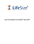
Attaching the Avaya Video MicPod 1000 Strain Relief Clip
Before attaching the strain relief clip to the codec, ensure the codec surface is clean (free of dirt, dust oil,
and other residues) and dry. The adhesive tape on the strain relief clip is intended for a single use. Attach
the strain relief clip to the codec and route the Avaya Video MicPod 1000 cable through the strain relief clip
as shown in the following illustration:
To obtain a replacement strain relief clip, contact Avaya.
6
Avaya 1010/1020 Installation Guide
Troubleshooting Installation Issues
Installation issues you may encounter with Avaya 1010/1020 typically involve display output issues,
improperly connected cables, or network bandwidth or connectivity. For more information about
troubleshooting issues you may encounter with Avaya 1010/1020, refer to the Avaya 1010/1020 User and
Administrator Guide.
Loose Cables
Improperly connected or loose cables are common causes of problems with hardware units. When
investigating a system problem, first inspect all external cable connections. Ensure that connections are
correct and secure, and that nothing is obstructing the cables.
No Power
To troubleshoot a power problem, complete the following steps:
1. Disconnect the power supply unit (PSU) from the codec and the AC source.
2. Plug a working appliance into the AC source to determine if the source is functioning.
3. If the AC source works, plug the PSU into the AC source, but do not connect the PSU to Avaya 1010/
1020. If the green LED on the PSU illuminates, the PSU is probably functioning.
4. Disconnect the PSU from the AC source. Connect the PSU to the Avaya codec. Reconnect the PSU to
the AC source. If the Avaya codec fails to boot and the green LED on the PSU dims, the codec may be
the source of the problem.
IP Address Displays Invalid Value
After you complete the initial configuration, if the IP address that appears at the top of the main screen
displays an invalid value, one of the following conditions may exist:
Condition
Resolution
The unit is configured to obtain an address using
DHCP and no DHCP server is available.
Verify that the unit is plugged into a network that has a
DHCP server present.
Note: The DHCP client self-assigns an address in
the 169.254 class B network and the red network
symbol
appears in the status bar on the main
screen.
Faulty Ethernet cable connection.
Replace the Ethernet cable with a high quality cable.
The unit is configured to use a static IP address, but
no IP address has been entered.
Identify and enter the necessary IP information.
Network connection is unavailable.
Inspect your network connection.
A red network symbol
on the main screen.
appears in the status bar
7
Avaya 1010/1020 Installation Guide
Camera Issues
Video from the camera appears in a small window on the main screen of the user interface above the
REDIAL list. If no video from the camera appears, do the following:
•
Ensure that the camera is properly connected to the Avaya codec as described in Installing Avaya
1010/1020. Only Avaya Video Camera 100 and Avaya Video Camera 200 are supported with Avaya
1010/1020.
•
Verify that the blue LED on the front of the camera is lit and not blinking.
•
From the main screen of the user interface, press
on the Avaya remote control to access the
System Menu. Press
to access page 2 of the System Information page. Ensure that the status of
the camera is Ready.
Improving a Dim Image
Adjust the HD Camera Brightness preference in User (or Administrator) Preferences : Diagnostics :
High Definition Camera. You can also add a light source to improve the subject’s illumination. Read more
at Room Configuration.
8
Avaya 1010/1020 Installation Guide
Status Icons
The following table identifies the icons that can appear in the system status bar.
Icon
Condition
Indicates that the communication subsystem is initializing. If this icon reappears after the
system has booted, a problem has occurred. Reboot the system.
Indicates that the system is initializing. When the system is initializing, functionality on the
main screen is disabled and no entries appear in the REDIAL list. This icon also appears
when a new device is connected to the system after the system boots and disappears
when the device is ready. If the icon persists, a problem has occurred and rebooting the
system is necessary.
Indicates that the system does not have an active microphone. Check the device’s
connections and then check the option you selected for the Active Microphone
preference.
Network Status
Identifies the network status, as follows:
connected (green indicator)
in progress (yellow indicator)
disconnected (red indicator)
Indicates the status of the registration process with the SIP server.
The yellow SIP icon appears when your Avaya system is trying to register with the SIP
server. If the registration fails, the red SIP icon appears.
System Overheating
The yellow indicator warns you when the system temperature is above normal operating
temperature. The codec adjusts fan speed automatically to cool itself.
The red indicator warns that the system is overheated and approaching the maximum
allowed operating temperature and will automatically reboot after reaching it.
Warning: Temperatures that require the codec to reboot can permanently damage codec
components. Ensure the room that houses the codec is properly ventilated and
temperature controlled.
9
© 2011 Avaya Inc.
All Rights Reserved.
Notices
While reasonable efforts have been made to ensure that the information in this document is complete and accurate at
the time of printing, Avaya assumes no liability for any errors. Avaya reserves the right to make changes and
corrections to the information in this document without the obligation to notify any person or organization of such
changes.
Documentation disclaimer
Avaya shall not be responsible for any modifications, additions, or deletions to the original published version of this
documentation unless such modifications, additions, or deletions were performed by Avaya. End User agree to
indemnify and hold harmless Avaya, Avaya's agents, servants and employees against all claims, lawsuits, demands
and judgments arising out of, or in connection with, subsequent modifications, additions or deletions to this
documentation, to the extent made by End User.
Link disclaimer
Avaya is not responsible for the contents or reliability of any linked Web sites referenced within this site or
documentation(s) provided by Avaya. Avaya is not responsible for the accuracy of any information, statement or
content provided on these sites and does not necessarily endorse the products, services, or information described or
offered within them. Avaya does not guarantee that these links will work all the time and has no control over the
availability of the linked pages.
Warranty
Avaya provides a limited warranty on this product. Refer to your sales agreement to establish the terms of the limited
warranty. In addition, Avaya's standard warranty language, as well as information regarding support for this product,
while under warranty, is available to Avaya customers and other parties through the Avaya Support Web site: http://
www.avaya.com/support. Please note that if you acquired the product from an authorized Avaya reseller outside of the
United States and Canada, the warranty is provided to you by said Avaya reseller and not by Avaya.
Licenses
THE SOFTWARE LICENSE TERMS AVAILABLE ON THE AVAYA WEBSITE, http://support.avaya.com/LicenseInfo
ARE APPLICABLE TO ANYONE WHO DOWNLOADS, USES AND/OR INSTALLS AVAYA SOFTWARE,
PURCHASED FROM AVAYA INC., ANY AVAYA AFFILIATE, OR AN AUTHORIZED AVAYA RESELLER (AS
APPLICABLE) UNDER A COMMERCIAL AGREEMENT WITH AVAYA OR AN AUTHORIZED AVAYA RESELLER.
UNLESS OTHERWISE AGREED TO BY AVAYA IN WRITING, AVAYA DOES NOT EXTEND THIS LICENSE IF THE
SOFTWARE WAS OBTAINED FROM ANYONE OTHER THAN AVAYA, AN AVAYA AFFILIATE OR AN AVAYA
AUTHORIZED RESELLER, AND AVAYA RESERVES THE RIGHT TO TAKE LEGAL ACTION AGAINST YOU AND
ANYONE ELSE USING OR SELLING THE SOFTWARE WITHOUT A LICENSE. BY INSTALLING, DOWNLOADING
OR USING THE SOFTWARE, OR AUTHORIZING OTHERS TO DO SO, YOU, ON BEHALF OF YOURSELF AND
THE ENTITY FOR WHOM YOU ARE INSTALLING, DOWNLOADING OR USING THE SOFTWARE (HEREINAFTER
REFERRED TO INTERCHANGEABLY AS "YOU" AND "END USER"), AGREE TO THESE TERMS AND
CONDITIONS AND CREATE A BINDING CONTRACT BETWEEN YOU AND AVAYA INC. OR THE APPLICABLE
AVAYA AFFILIATE ("AVAYA").
Avaya grants End User a license within the scope of the license types described below. The applicable number of
licenses and units of capacity for which the license is granted will be one (1), unless a different number of licenses or
units of capacity is specified in the Documentation or other materials available to End User. "Designated Processor"
means a single stand-alone computing device. "Server" means a Designated Processor that hosts a software
application to be accessed by multiple users. "Software" means the computer programs in object code, originally
licensed by Avaya and ultimately utilized by End User, whether as stand-alone products or pre-installed on Hardware.
"Hardware" means the standard hardware originally sold by Avaya and ultimately utilized by End User.