1
Avaya 1030 Installation Guide
Issue 1
June 2010
© 2010 Avaya Inc.
All Rights Reserved.
Notices
While reasonable efforts have been made to ensure that the information in this document is complete and accurate
at the time of printing, Avaya assumes no liability for any errors. Avaya reserves the right to make changes and
corrections to the information in this document without the obligation to notify any person or organization of such
changes.
Documentation disclaimer
Avaya shall not be responsible for any modifications, additions, or deletions to the original published version of this
documentation unless such modifications, additions, or deletions were performed by Avaya. End User agrees to
indemnify and hold harmless Avaya, Avaya's agents, servants and employees against all claims, lawsuits,
demands and judgments arising out of, or in connection with, subsequent modifications, additions or deletions to
this documentation, to the extent made by End User.
Link disclaimer
Avaya is not responsible for the contents or reliability of any linked Web sites referenced within this site or
documentation(s) provided by Avaya. Avaya is not responsible for the accuracy of any information, statement or
content provided on these sites and does not necessarily endorse the products, services, or information described
or offered within them. Avaya does not guarantee that these links will work all the time and has no control over the
availability of the linked pages.
Warranty
Avaya provides a limited warranty on this product. Refer to your sales agreement to establish the terms of the
limited warranty. In addition, Avaya's standard warranty language, as well as information regarding support for this
product, while under warranty, is available to Avaya customers and other parties through the Avaya Support Web
site: http://www.avaya.com/support. Please note that if you acquired the product from an authorized Avaya reseller
outside of the United States and Canada, the warranty is provided to you by said Avaya reseller and not by Avaya.
Licenses
THE SOFTWARE LICENSE TERMS AVAILABLE ON THE AVAYA WEBSITE, http://support.avaya.com/LicenseInfo
ARE APPLICABLE TO ANYONE WHO DOWNLOADS, USES AND/OR INSTALLS AVAYA SOFTWARE,
PURCHASED FROM AVAYA INC., ANY AVAYA AFFILIATE, OR AN AUTHORIZED AVAYA RESELLER (AS
APPLICABLE) UNDER A COMMERCIAL AGREEMENT WITH AVAYA OR AN AUTHORIZED AVAYA RESELLER.
UNLESS OTHERWISE AGREED TO BY AVAYA IN WRITING, AVAYA DOES NOT EXTEND THIS LICENSE IF
THE SOFTWARE WAS OBTAINED FROM ANYONE OTHER THAN AVAYA, AN AVAYA AFFILIATE OR AN AVAYA
AUTHORIZED RESELLER, AND AVAYA RESERVES THE RIGHT TO TAKE LEGAL ACTION AGAINST YOU AND
ANYONE ELSE USING OR SELLING THE SOFTWARE WITHOUT A LICENSE. BY INSTALLING,
DOWNLOADING OR USING THE SOFTWARE, OR AUTHORIZING OTHERS TO DO SO, YOU, ON BEHALF OF
YOURSELF AND THE ENTITY FOR WHOM YOU ARE INSTALLING, DOWNLOADING OR USING THE
SOFTWARE (HEREINAFTER REFERRED TO INTERCHANGEABLY AS "YOU" AND "END USER"), AGREE TO
THESE TERMS AND CONDITIONS AND CREATE A BINDING CONTRACT BETWEEN YOU AND AVAYA INC.
OR THE APPLICABLE AVAYA AFFILIATE ("AVAYA").
Avaya grants End User a license within the scope of the license types described below. The applicable number of
licenses and units of capacity for which the license is granted will be one (1), unless a different number of licenses
or units of capacity is specified in the Documentation or other materials available to End User. "Designated
Processor" means a single stand-alone computing device. "Server" means a Designated Processor that hosts a
software application to be accessed by multiple users. "Software" means the computer programs in object code,
originally licensed by Avaya and ultimately utilized by End User, whether as stand-alone products or pre-installed
on Hardware. "Hardware" means the standard hardware originally sold by Avaya and ultimately utilized by End
User.
2
Avaya 1030 Installation Guide
License types
Designated System(s) License (DS). End User may install and use each copy of the Software on only one
Designated Processor, unless a different number of Designated Processors is indicated in the Documentation or
other materials available to End User. Avaya may require the Designated Processor(s) to be identified by type,
serial number, feature key, location or other specific designation, or to be provided by End User to Avaya through
electronic means established by Avaya specifically for this purpose.
Shrinkwrap License (SR). Customer may install and use the Software in accordance with the terms and conditions
of the applicable license agreements, such as "shrinkwrap" or "clickthrough" license accompanying or applicable to
the Software ("Shrinkwrap License"). (see "Third Party Components" for more information).
Copyright
Except where expressly stated otherwise, no use should be made of materials on this site, the Documentation(s)
and Product(s) provided by Avaya. All content on this site, the documentation(s) and the product(s) provided by
Avaya including the selection, arrangement and design of the content is owned either by Avaya or its licensors and
is protected by copyright and other intellectual property laws including the sui generis rights relating to the
protection of databases. You may not modify, copy, reproduce, republish, upload, post, transmit or distribute in any
way any content, in whole or in part, including any code and software. Unauthorized reproduction, transmission,
dissemination, storage, and or use without the express written consent of Avaya can be a criminal, as well as a civil,
offense under the applicable law.
Third Party Components
Certain software programs or portions thereof included in the Product may contain software distributed under third
party agreements ("Third Party Components"), which may contain terms that expand or limit rights to use certain
portions of the Product ("Third Party Terms"). Information regarding distributed Linux OS source code (for those
Products that have distributed the Linux OS source code), and identifying the copyright holders of the Third Party
Components and the Third Party Terms that apply to them is available on the Avaya Support Web site:
http://support.avaya.com/Copyright
Preventing toll fraud
"Toll fraud" is the unauthorized use of your telecommunications system by an unauthorized party (for example, a
person who is not a corporate employee, agent, subcontractor, or is not working on your company's behalf). Be
aware that there can be a risk of toll fraud associated with your system and that, if toll fraud occurs, it can result in
substantial additional charges for your telecommunications services.
Avaya fraud intervention
If you suspect that you are being victimized by toll fraud and you need technical assistance or support, call
Technical Service Center Toll Fraud Intervention Hotline at +1-800-643-2353 for the United States
and Canada. For additional support telephone numbers, see the Avaya Support Web site:
http://support.avaya.com
Suspected security vulnerabilities with Avaya products should be reported to Avaya by sending mail to:
[email protected].
Trademarks
Avaya and Aura are trademarks of Avaya, Inc.
Avaya is a registered trademark of Avaya Inc.
Avaya Aura is a trademark of Avaya Inc.
All non-Avaya trademarks are the property of their respective owners.
Downloading documents
For the most current versions of documentation, see the Avaya Support Web site:
http://www.avaya.com/support
Contact Avaya Support
Avaya provides a telephone number for you to use to report problems or to ask questions about your product. The
support telephone number is 1-800-242-2121 in the United States. For additional support telephone numbers, see
the Avaya Web site: http://www.avaya.com/support
Patent Notice
For patents covering LifeSize® products, refer to http://www.lifesize.com/support/legal.
Avaya 1030 Installation Guide
3
Preparing for Installation
As you prepare to install an Avaya video communications system, consider the physical
conditions of the room, compatibility with displays and your network configuration and
settings. Avaya recommends you collect your network settings and system identification
information before you begin installation. Refer to “Initial Configuration” on page 6, which
explains what information you need to collect and provides space to record it.
Room Configuration
The size, shape, layout and occupancy of the room dictate where you place your video
conferencing components. For example, in a multi-user conference room, place an Avaya
Video MicPod 1000 or Avaya Video Conference Phone 1000 at the center of the participants
as their detection patterns are omnidirectional.
Warning: Avoid routing cables from the codec across foot-traffic areas as tripping on
the cables can cause both personal injury and permanent damage to the connectors in
the cables and codec. If cables must cross foot-traffic areas, use some form of cable
management system or strategy to avoid the possibility of tripping.
The lighting in your environment affects image quality. The optimal lighting for Avaya
systems is 300 to 500 LUX. If light levels are too low, consider adding artificial lighting.
Indirect light from shaded sources or reflected light from pale walls often produces excellent
results. Avoid the following:
•
direct sunlight on the subject matter, the background, or the camera lens
•
direct illumination of the subject matter and camera lens
•
colored lighting
•
harsh side lighting or strong light from above
Consult your administrator for specific lighting requirements for your environment.
Avaya 1030 Installation Guide
4
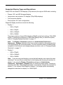
Supported Display Types and Resolutions
Avaya 1030 can connect to HD displays (720p minimum) through an HDMI cable, including:
•
Plasma, LCD, and LED flat panel displays
•
Large screen rear projection TV displays (720p/1080p displays)
•
Front projection displays
•
Rear projector A/V room configurations
Supported display resolutions include the following:
•
Display 1:
-
1280 x 720p60
-
1280 x 768p60
-
1920 x 1080p30
-
1920 x 1080i60
The primary output on Avaya 1030 defaults to 720p60 and will work with any 720p HDMI
display. To change the resolution for 1080 HDMI displays after you install the system,
refer to “Changing Display Resolution” on page 17.
Note: The Display 1 Resolution preference in Administrator Preferences :
Appearance : Displays defaults to Auto if you select an option for this preference that
is not supported by the connected display. For more information about troubleshooting
exceptions to this behavior and changing display resolution, refer to “Changing Display
Resolution” on page 17.
•
Display 2:
-
1280 x 720p60
-
1920 x 1080p30
-
1920 x 1080i60
Note: If you are using dual displays, ensure that both displays can support the same
resolutions. You can choose a resolution for both displays by choosing a resolution for
display 1 only using the Display 1 Resolution preference in Administrator
Preferences : Appearance : Displays after you install the Avaya system. Choosing a
resolution other than 1280x768p60 for display 1 automatically changes the resolution for
display 2. If you choose 1280x768p60 for display 1, the Avaya system automatically
changes the resolution for display 2 to 1280x720p60.
5
Avaya 1030 Installation Guide
Placement Behind a Firewall
Avaya recommends that you place your system behind a firewall and block, at minimum, the
following ports:
•
22 (SSH)
•
23 (Telnet)
•
80 (HTTP)
•
443 (HTTPS)
If you require these ports remain open, ensure that you change the default administrator and
command line interface passwords to be very secure. For information about changing the
default administrator password, refer to the Avaya Video Communications Systems
Administrator Guide.
You can also disable SSH and web access on the system by configuring preferences in the
user interface. By default, Telnet access is disabled. For more information, refer to the
Avaya Video Communications Systems Administrator Guide.
Network Bandwidth
Poor audio and video quality may result from insufficient bandwidth on your network. Avaya
recommends that your network be capable of at least 1 Mb/s (incoming and outgoing) for a
high definition video call. During video calls with lower bandwidths, Avaya systems
automatically select the best resolution that can be achieved with the available bandwidth.
Initial Configuration
During the installation process, your Avaya system prompts you to configure it for the first
time. Avaya recommends that you gather all the necessary information prior to installation.
The following sections provide guidelines for collecting and a means of recording this data.
You may need to consult your network administrator for network settings and system
identification information.
Note:
The initial configuration screens also appear when you perform a system reset. For
more information, refer to “Restoring Default Settings” in the Avaya Video
Communications Systems Administrator Guide.
Language
Select the language to display in the user interface. The default is English.
Avaya 1030 Installation Guide
6
Administrator and User Passwords
Some functions and preferences available from the user interface are accessible only to
administrative users with a password. For security reasons, Avaya recommends that you
change the default administrator password (1 2 3 4) during the initial configuration.
Optionally, you can set a user password to control access to user preferences that enable
the user to do the following:
•
Change the appearance of the user interface.
•
Specify how calls are answered.
•
Configure audio settings.
•
Change cameras and DVI-I input settings.
•
Reboot the system.
The administrator and user passwords can contain any combination of the numbers 0-9 and
the symbols * (star) and # (pound) up to 16 characters in length.
Note:
If you set a user password, you can also use the administrator password to access
user preferences.
Administrator Password: ________________________________________________
User Password: _______________________________________________________
7
Avaya 1030 Installation Guide
System Identification
Information that identifies the system to users appears throughout the user interface.
Set the Location preference to your location. The default is the United States. The Time
Zone preference sets the system time that appears in the status bar on the main page of the
user interface. It defaults to Greenwich Mean Time. You must set this preference even if you
specify an NTP server during the initial configuration (refer to “Network Settings” on page 8).
The System Name, Video Number, and Voice Number appear in the user interface on the
main screen. The system name may also appear in the local and corporate directories.
Avaya recommends that you change the default system name to one that meaningfully
identifies the system to your users.
System Name: (to identify this installation in the network): _______________________
Video Number: ________________________________________________________
Voice Number: ________________________________________________________
Network Settings
By default, DHCP is enabled on Avaya systems. If you choose Disabled for the DHCP
preference, you must enter an IP address (the locally configured IP address if not assigned
by a DHCP server), Subnet Mask (used to partition the IP address into a network and host
identifier), and Default Gateway (the IP address of the default gateway the system uses).
IP Address: ___________________________________________________________
Subnet Mask: _________________________________________________________
Default Gateway: ______________________________________________________
You can enter the Hostname of the system. If you do not have a DHCP server that
automatically sets a DNS server, you can enter the IP addresses to configure DNS Servers.
You can also define the domain names to search when resolving hostnames. DNS
translates names of network nodes into addresses; specify this preference to use DNS to
resolve the hostnames of devices to IP addresses.
Hostname: ____________________________________________________________
DNS Servers: __________________________________________________________
Name Search Domains: _________________________________________________
If you choose an option other than Auto (the default) for the Network Speed preference,
ensure that the option matches the speed and duplex configured on your network switch.
Network Speed: ________________________ Network Duplex: _________________
Avaya 1030 Installation Guide
8
You can enter the hostname or IP address of a Network Time Protocol (NTP) server to set
the system date and time automatically. The Avaya system ignores the value you specify for
the NTP Server Hostname if the DHCP preference is set to Enabled and the DHCP server
can pass an NTP server address to the Avaya system.
Network Time Protocol (NTP): ____________________________________________
Audio Preferences: Active Microphone
The default for the Active Microphone preference is Auto. The system detects attached
audio input devices and selects one to be the active microphone in the following order:
•
phone
•
microphone in
If you wish to use a device connected to line in on the codec as the active microphone, you
must choose line in manually for Active Microphone.
The Active Microphone field in the System Information page shows which device is
functioning as the active microphone. When the value is None, the No Active Microphone
indicator
appears in the status bar on the main screen of the user interface indicating
that no active microphone is available. You can view the System Information page after
you install the system and complete the initial configuration. From the main screen, press
the
button on the Avaya remote control.
Note:
If you choose Line In or Line In (No AEC) as the active microphone, and a device is
not connected to line in on the codec, the System Information page shows line in
as the status for Active Microphone. The No Active Microphone indicator does not
appear in the user interface.
The Microphone In (No AEC) and Line In (No AEC) options for the Active Microphone
preference are for use with a microphone that has its own acoustic echo canceller (AEC).
Audio Preferences: Active Microphone Volume
You can adjust the audio level for the active microphone by selecting Active Microphone
Volume and pressing OK on the Avaya remote control.
Note:
9
A built-in acoustic echo canceller and noise reducer are active when Microphone In
or Line In is the active microphone. The built-in acoustic echo canceller
automatically attempts to adjust audio volume for optimum levels.
Avaya 1030 Installation Guide
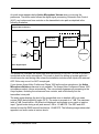
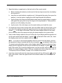
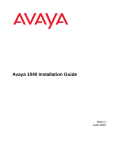
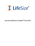
An audio meter appears below Active Microphone Volume when you access the
preference. The audio meter follows the digital signal processing, Automatic Gain Control
(AGC), and volume and tone controls on the transmitted voice path as depicted in the
following illustration.
Avaya Video Conference
Transmitted
Voice/Audio
Line In
A/D
Avaya
Video
A/D
Volume and
Tone Control
DSP, AGC,
Echo Canceller
Audio Meter
Other Digital Inputs
The dotted line illustrates the audio path when Microphone In (No AEC) or Line In (No AEC)
is selected as the active microphone. This mode is useful for setting up system gains but
should never be used during calls unless the installation includes audio inputs with external
AEC. Echo may occur if no AEC is employed.
If you choose Avaya Video Conference Phone 1000 as the active microphone, the Active
Microphone Volume preference is not available. The Avaya Video Conference Phone 1000
microphones adjust volume automatically. The voice stream bypasses all processing in the
Avaya system, including the volume and tone controls, and is fed directly into the
transmitted voice path.
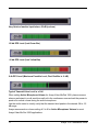
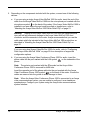
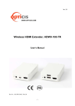
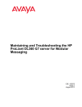
The audio meter displays the level of the transmitted voice in decibels (dB) root mean
square (RMS) below digital full scale (DFS). The meter is accurate to ± 1 dB. The maximum
level is 0 dB. Levels below –50 dB are not displayed, and indicate a very quiet or inactive
input. Typical levels during a call peak around –28 to –22 dB DFS. The AEC and AGC
attempt to keep the RMS transmit level below –20 dB DFS. The following images show what
appears in an audio meter at various levels.
Avaya 1030 Installation Guide
10
Very Quiet or Inactive Input below -50 dB (no bars)
-20 db DFS Level (Last Green Bar)
-10 db DFS Level (Last Yellow Bar)
0 db DFS Level (Maximum Possible Level; First Red Bar is -9 dB)
Typical Transmit Voice Level in a Call
When setting Active Microphone Volume for Avaya Video MicPod 1000, place someone
where a participant in a call would normally sit in the conference room and ask the person to
speak at a normal volume facing the active microphone.
Use the audio meter to visually verify that the transmit level peaks in the desired -28 to -22
dB range.
Avaya recommends a volume setting of 5 to 8 for Active Microphone Volume for most
Avaya Video MicPod 1000 applications.
11
Avaya 1030 Installation Guide
If you set Active Microphone Volume to line in when using an external mixer or amplified
microphone, follow these steps:
1. Select Line in (no AEC) for Active Microphone.
2. Position someone approximately one meter from the microphone, facing it, speaking at
a normal volume.
3. Adjust the Active Microphone Volume and the external mixer output level until the
meter peaks in the -28 to -22 dB range. Avaya recommends you adjust the external
mixer volume so that you achieve peak levels in the -28 to -22 dB range of the audio
meter with the Active Microphone Volume control set to no less than 5 or greater than
15.
4. If the microphone or mixer you use employs an echo canceller, no further adjustments
are necessary. Otherwise, select Line In for Active Microphone. This turns on the
Avaya system’s echo canceller, noise reduction, and automatic gain control functions. If
you do not use an echo canceller, you may experience severe echo effects.
5. After the adjustment, check that the peak levels when speaking normally one meter from
the microphone are in the -28 to -22 dB range. The AGC attempts to keep the transmit
level below -20 dB, which is the green range of the bar graph.
An audio meter is also available for the Line In Volume preference for setting an audio level
for a device connected to line in on the codec when line in is not selected as the active
microphone.
Audio Preferences: Video and Voice Call Output
If you plan to use external speakers other than Avaya Video Conference Phone 1000 for
audio output in both video and voice calls, ensure that the Video Call Audio Output and
Voice Call Audio Output preferences are set to Line Out. By default, Video Call Audio
Output is set to Line Out; Voice Call Audio Output is set to Phone. If you are using Avaya
Video Conference Phone 1000 for audio, set these preferences to Phone.
Audio Preferences: Testing Speakers
You can also test the primary output speakers for the appropriate audio level or to ensure
they are working properly. Select Auto for Primary Audio Output Test to cycle through a
test on your available speakers. The test continues until you select Off. You can also send
the tone to either the left or right channel by choosing Test Left or Test Right. The tone is
sent simultaneously to both line out and the HD video out of display 1.
Avaya 1030 Installation Guide
12
Avaya 1030 Components
Your Avaya 1030 package contains the following components:
•
One of the following audio components:
-
Avaya Video MicPod 1000—see “Optional Peripherals” on page 19 for the dual
Avaya Video MicPod 1000 option
-
Avaya Video Conference Phone 1000
•
Avaya Video Camera 200 with standard 3 meter (9.8 foot) cable
•
Avaya 1030 Codec
•
Avaya Remote Control (including three AAA batteries)
•
Quick reference card
•
Documentation CD
Installing Avaya 1030
Before you install an Avaya video communications system, read the document Avaya Safety
and Regulatory Notices for important safety information. The document is available on the
documentation CD-ROM and from support.avaya.com.
Warning: Exercise care when connecting cables to the codec to avoid damaging
cables or the connectors on the codec. Face the back of the codec or ensure that all
connectors are visible when connecting a cable to the codec.
To install the components of your Avaya system, remove all components from the product
packaging, including cables, and place them in the desired positions in your conference
room.
Warning: Do not place anything on top of or adjacent to the codec that can obstruct
air flow around the unit or generate heat. Doing so can cause the system to overheat
and reboot. Prolonged overheating can result in damage to the codec. Ensure the room
that houses the codec is properly ventilated and temperature controlled.
Refer to the Avaya quick reference card included with your system for a visual depiction of
the proper setup. The numbers that appear on the quick reference card correspond to the
following steps:
13
Avaya 1030 Installation Guide
1. Open the battery compartment on the back side of the remote control.
a. Before inserting the batteries, stretch each of the two straps across the outer battery
slot closest to it.
b. Insert the two outer batteries, negative end (-) first against the spring, then press the
positive (+) end into place, trapping the cloth straps beneath the batteries.
c.
Lay the longer cloth strap over both batteries and insert the center battery’s negative
end against the spring first to trap the longer cloth strap beneath it. Then press the
positive end of the battery into place.
d. Lay the ends of the cloth straps over the center battery and install the cover.
2. To connect the Avaya Video Camera 200, insert the HDMI cable into the HD port on the
rear side of the camera and plug the opposite end into the port marked with the HD in
symbol
on the back of the codec. Insert the power adapter cable into the power
port on the rear side of the camera and plug the power adapter into a power outlet.
3. Insert a video display cable into the port on the rear of your display and the opposite end
into the port marked with the display 1 symbol
on the back of the codec (3a). Insert
the display power cord into a power outlet on the wall.
Note: If you plan to use external speakers that are not built into the display, connect
the speakers to the port marked with the line out symbol
on the back of the codec.
To connect a second display, insert a video display cable into the port on the rear of your
display and the opposite end into the port marked with the display 2 symbol
on the
back of the codec (3b). Insert the display power cord into a power outlet on the wall. By
default, the second display is blank. After you complete the initial configuration, refer to
“Configuring a Second Display” on page 18 to complete this process.
4. Insert the network cable into the network port marked with the LAN symbol
on the
back of the codec. Insert the opposite end of the network cable into a network port on
the wall.
Avaya 1030 Installation Guide
14
5. Depending on the components included with the system, connect one of the following
devices:
a. If you are using a single Avaya Video MicPod 1000 for audio, insert the end of the
cable from the Avaya Video MicPod 1000 into the microphone port marked with the
microphone symbol
on the back of the codec. If the Avaya Video MicPod 1000 is
installed in an area where the cord could be pulled or tripped upon, refer to
“Attaching the Avaya Video MicPod 1000 Strain Relief Clip” on page 21.
Warning: Tripping on the Avaya Video MicPod 1000 cord can cause personal
injury as well as permanent damage to the Avaya Video MicPod 1000 cord
connector and the connector in the codec. Avaya recommends that you use the
cable strain relief clip included in the Avaya Video MicPod 1000 product box as
described in “Attaching the Avaya Video MicPod 1000 Strain Relief Clip” on
page 21.
If you are using dual Avaya Video MicPod 1000s for audio, refer to “Configuring
Dual Avaya Video MicPod 1000s” on page 20 for a description of supported
configuration options.
b. If you are using the Avaya Video Conference Phone 1000 for audio, insert the
phone cable into the port marked with the LAN symbol
on the underside of the
phone.
Note: The exterior port marked with the
symbol on the Avaya Video
Conference Phone 1000 is reserved for future use.
Insert the opposite end of the phone cable into the port marked with the Avaya
Video Conference Phone 1000 symbol
on the back of the codec. Ensure the
cables are secured into the guides to avoid damage to them.
Note: When the Avaya Video Conference Phone 1000 is connected to an Avaya
video communications system, you are unable to configure it as a standalone
speakerphone. Configure your system using the Avaya video communications
system interface.
15
Avaya 1030 Installation Guide
6. Insert the cord from the power adapter into the power outlet marked
on
the back of the codec. Insert one end of the power cord into the power adapter and the
opposite end into a power outlet.
The Avaya system starts, illuminating a blue LED on the front of the codec. See “Status
Icons” on page 26 for more information about the state of the system as it boots or as
conditions change.
The camera initializes the first time it is connected to a codec; this process takes
approximately 90 seconds.
Warning: Do not disturb or disconnect the devices during this time as you may
damage the system.
7. An Initial Configuration screen appears and prompts you to configure the system.
Refer to “Initial Configuration” on page 6 and the information you collected there
previously to guide you through your configuration choices. Use the arrow keys on the
remote control to navigate the preferences that appear in the initial configuration
screens. Icons and their descriptions that appear at the bottom of each screen
correspond to keys on the remote control and indicate what operations are available for
the screen or a selected object.
If the initial configuration screen does not appear and the display is blank, refer to
“Troubleshooting Installation Issues” on page 22.
The bottom of the screen contains the system status bar and the navigation bar. The
system status bar indicates system and network status. When the system is booting,
status also appears at the top of the REDIAL list to indicate the current state of the
system. See “Status Icons” on page 26 for an explanation of status icons you may
encounter.
Locking the Avaya Codec
You can lock the Avaya codec with a secure loop to prevent physical removal of the device.
For assistance, contact Avaya Technical Services.
Avaya 1030 Installation Guide
16
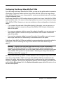
Changing Display Resolution
The primary output on Avaya 1030 defaults to 720p60 and will work with any 720p HDMI
display.
To change display resolution, navigate to Administrator Preferences : Appearance :
Displays and choose Display 1 Resolution. You can change the resolution to
1920x1080i60 or 1920x1080p30 and it will work with most 1080 HDMI displays. However,
some 1080p displays will not work with 1080p30 mode and the display may be blank. In this
case you must configure the display resolution from either the Avaya Video Conference
Phone 1000 (refer to “Configuring Display Output from Avaya Video Conference Phone
1000” on page 22) or from the web administration interface for the Avaya system (refer to
the Avaya Video Communications Systems Administrator Guide). Avaya recommends that
before you change the display resolution to 1920x1080p30, ensure that you can access the
Display 1 Resolution preference using one of these methods.
Note:
To access the web administration interface for the system, HTTP access must be
set to Enabled (the default) in Administrator Preferences : Security : General
and you must identify the IP address of the Avaya system. The IP address appears
in the upper right corner on the main page of the user interface.
Configuring a Second Display
If you installed a second display, you must configure it. From the main screen of the user
interface, press
on the Avaya remote control to access the System Menu. Navigate to
Administrator Preferences : Appearance : Layout and choose Display 2 Layout, which,
by default is set to None. Choose Presentations + DVI-I Input to configure the second display. When configured, display 2 shows either DVI-I input or presentations (near and far
end) when a presentation is sent or received.
The following conditions apply when using two displays with Avaya 1030:
•
The presentation icon that appears on screen during a call to indicate that a near or far
end presentation is in progress appears in display 1. For a presentation sent from a far
end participant, the receiving presentation icon
appears in the upper left corner of
display 1; for a presentation sent from the near end, the sending presentation icon
appears in the lower right corner of display 1.
•
Only presentation video or DVI-I input is supported for display 2. Background image and
color preferences that appear in User Preferences : Backgrounds and Administrator
Preferences : Appearance : Backgrounds are available for display 1 only. The user
interface appears only in display 1.
17
Avaya 1030 Installation Guide
Optional Peripherals
You can connect the following optional peripherals to enhance your Avaya system:
Peripheral
Usage
DVI-I In
DVI-I port for connecting laptops for presentations or to share PC data. For
devices and PCs with VGA output, Avaya includes a DVI-A to VGA cable.
An HDMI source can be used with an adapter. For more information about
supported resolutions and audio support, refer to the Avaya Video
Communications Systems Administrator Guide.
Microphone in
For use with a single or dual Avaya Video MicPod 1000 configuration.
In a single Avaya Video MicPod 1000 configuration, you can add an Avaya
Video MicPod 1000 extension cable (15 meters, 49.2 feet) to the Avaya
Video MicPod 1000.
In a dual Avaya Video MicPod 1000 configuration, you use a combination
of two Avaya Video MicPod 1000s, one splitter cable, and extension
cables in large rooms to create wider coverage of audio input. Refer to
“Configuring Dual Avaya Video MicPod 1000s” on page 20.
Audio In (Line In)
For use with an external line level audio input, in addition to the Avaya
Video Conference Phone 1000 or Avaya Video MicPod 1000.
Audio Out (Line Out)
For use with external line level output speakers that are not built into
display 1 or with a headset (left plus right).
Warning: Excessive sound pressure from earphones and
headphones can cause hearing loss.
USB Port
Avaya 1030 Installation Guide
Reserved for future use.
18
Configuring Dual Avaya Video MicPod 1000s
If you are using dual Avaya Video MicPod 1000s, you can use the splitter cable to connect a
combination of extension cables and two Avaya Video MicPod 1000s to the single Avaya
Video MicPod 1000 port on your Avaya codec for maximum omnidirectional audio coverage
in large conference rooms.
Dual Avaya Video MicPod 1000 configurations are limited to two Avaya Video MicPod 1000s
and one splitter cable. (You cannot use multiple splitters to connect to more than two Avaya
Video MicPod 1000s.) However, you can use variations on three configurations of extension
cables:
•
If you connect the male end of the splitter directly to the codec, you can use none, or
one extension cable to connect an Avaya Video MicPod 1000 to each of the female
ends of the splitter.
•
If you use one extension cable to connect the codec to the splitter, you can use none, or
one extension cable to connect an Avaya Video MicPod 1000 to each of the female
ends of the splitter.
•
If you use two extension cables to connect the codec to the splitter, you must connect
both Avaya Video MicPod 1000s directly to the female ends of the splitter.
If the Avaya Video MicPod 1000s are installed in an area where the cord could be pulled or
tripped upon, refer to “Attaching the Avaya Video MicPod 1000 Strain Relief Clip” on
page 21.
Warning: Tripping on the cord can cause personal injury as well as permanent
damage to the Avaya Video MicPod 1000 cord connector and the connector in the
codec. Avaya recommends that you use the cable strain relief clip included in the Avaya
Video MicPod 1000 product box as described in “Attaching the Avaya Video MicPod
1000 Strain Relief Clip” on page 21.
An Avaya codec detects any splitter or cable attached to the microphone input of the codec
as an Avaya Video MicPod 1000. If an Avaya Video MicPod 1000 is not attached to the
extension or splitter cable and the microphone input is selected as the active microphone,
no audio is available. The No Active Microphone indicator does not appear in the status bar
and the Active Microphone field in the System Information page reports Microphone In as
the active microphone.
19
Avaya 1030 Installation Guide
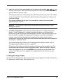
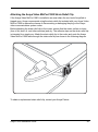
Attaching the Avaya Video MicPod 1000 Strain Relief Clip
If the Avaya Video MicPod 1000 is installed in an area where the cord could be pulled or
tripped upon, Avaya recommends using the strain relief clip included with your Avaya Video
MicPod 1000 to reduce the chance of disconnecting or damaging the plug or the Avaya
video communications system codec.
Before attaching the strain relief clip to the codec, ensure that the codec surface is clean
(free of dirt, dust, oil, and other residues) and dry. The adhesive tape on the strain relief clip
is intended for a single use. Attach the strain relief clip to the codec and route the Avaya
Video MicPod 1000 cable through the strain relief clip as shown in the following diagram.
To obtain a replacement strain relief clip, contact your Avaya Partner.
Avaya 1030 Installation Guide
20
Troubleshooting Installation Issues
Installation issues that you may encounter with your Avaya system typically involve issues
with display output, improperly connected cables, or network bandwidth or connectivity. For
information about troubleshooting other issues that users may encounter with Avaya
systems refer to the Avaya Video Communications Systems User Guide.
Improperly connected or loose cables are common causes of problems with hardware units.
When investigating a system problem, first inspect all the external controls and cable
connections. Ensure that connections are correct and secure, and that nothing is obstructing
the cables.
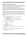
Configuring Display Output from Avaya Video Conference Phone 1000
If you are using Avaya Video Conference Phone 1000 and your display shows the initial
configuration screen but the image is distorted and unusable or the display is blank, you can
configure the display from the Avaya Video Conference Phone 1000 user interface. Follow
these steps:
1. Ensure that no calls are in progress.
2. Log in to the Admin Menu on your Avaya Video Conference Phone 1000.
a. Press
sequentially when the phone is idle.
b. Enter the administrator password (1 2 3 4 by default) and press
.
3. Press 1 on the keypad to select Preferences.
4. Press 1 on the keypad to select Display 1.
5. Press the
key to select Auto.
6. Press the
key to accept your change(s).
Note: If you remain idle on any preference screen for two minutes, you return to the
main screen.
7. When you have finished setting preferences, press the
8. Press
21
key to save them.
to return to the previous screen.
Avaya 1030 Installation Guide
No Power
To troubleshoot a power problem, complete the following steps:
1. Disconnect the power supply unit (PSU) from the Avaya codec and the AC source.
2. Plug an appliance you know works into the AC source to determine if the source works.
3. If the AC source works, plug the PSU into the AC source, but do not connect the PSU to
the Avaya codec. If the green LED on the PSU illuminates, the PSU is probably good.
4. Disconnect the PSU from the AC source. Connect the PSU to the Avaya codec.
Reconnect the PSU to the AC source. If the Avaya codec fails to boot and the green
LED on the PSU dims, the codec may be the source of the problem.
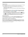
IP Address Displays Invalid Value
After you complete the initial configuration, if the IP address that appears at the top of the
main screen displays an invalid value, one of the following conditions may exist:
Condition
Resolution
The unit is configured to obtain an address
using DHCP and no DHCP server is
available.
Verify that the unit is plugged into a network that has a DHCP
server present.
Note: The DHCP client self-assigns an
address in the 169.254 class B network
and the red network symbol
appears in
the status bar on the main screen.
Faulty Ethernet cable connection.
Replace the Ethernet cable with a high quality cable.
The unit is configured to use a static IP
address, but no IP address has been
entered.
Identify and enter the necessary IP information if you disable
DHCP.
Network connection is unavailable.
Inspect your network connection.
A red network symbol
appears in the
status bar on the main screen.
Avaya 1030 Installation Guide
22
Camera Issues
Video from the camera appears in a small window on the main screen of the user interface
above the REDIAL list. If no video from the camera appears, do the following:
•
Ensure that the camera is properly connected to the Avaya codec as described in
“Installing Avaya 1030” on page 14.
•
Verify that the blue LED on the front of the camera is lit and not blinking, indicating that
power is active.
•
From the main screen of the user interface, press
on the Avaya remote control to
access the System Menu. Press
to access page 2 of the System Information
page. Ensure that the status of the camera is Ready.
•
Ensure that the primary input is set to the high definition camera. Press
on the
remote control. If Primary Input : HD Camera does not appear at the top of the screen,
press
to display the Primary Input selection dialog. Use the arrow keys on the
remote control to select the appropriate high definition camera and press OK.
Improving a Dim Image
If the image appears too dim, you can adjust the HD Camera Brightness preference in
User (or Administrator) Preferences : Diagnostics : High Definition Camera.
Attached Video Input Device Not Working
When you connect a video input device that has capabilities not supported by an Avaya
system, the status Out of range appears on the System Information page for that input.
The device may be in a mode that the codec does not support. Changing the mode may
help. Otherwise, the device is not supported.
23
Avaya 1030 Installation Guide
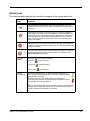
Status Icons
The following table identifies the icons that can appear in the system status bar.
Icon
Condition
Indicates that the communication subsystem is initializing. If this icon
reappears after the system has booted, a problem has occurred. Reboot
the system.
Indicates that the system is initializing. When the system is initializing,
functionality on the main screen is disabled and no entries appear in the
REDIAL list. This icon also appears when a new device is connected to
the system after the system boots and disappears when the device is
ready. If the icon persists, a problem has occurred and rebooting the
system is necessary.
Indicates that the connected phone has been detected and the phone is
initializing. If the icon persists, a problem has occurred and rebooting the
system is necessary.
Indicates that the system does not have an active microphone. Check the
device’s connections and then check the option you selected for the
Active Microphone preference.
Network
Status
Identifies the network status, as follows:
connected
in progress
disconnected
System
Overheating
(green indicator)
(yellow indicator)
(red indicator)
This yellow indicator warns you when the system temperature is
above normal operating temperature. The codec adjusts fan speed
automatically to cool itself.
This red indicator warns that the system is overheated and
approaching the maximum allowed operating temperature and will
automatically reboot after reaching it.
Warning: Temperatures that require the codec to reboot can permanently
damage codec components. Ensure the room that houses the codec is
properly ventilated and temperature controlled.
Avaya 1030 Installation Guide
24