1
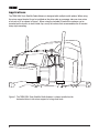
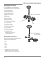
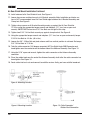
OWNER’S MANUAL
READ
THIS
FIRST!
SIR4
LONG-HAUL TRUCK AND RV SATELLITE RADIO ANTENNA
Table Of Contents
About Installation. . . . . . . . . . . . . . . . . . . . . . . . . . . . . . . . . . . . . . . . . . . . . . . . . . . . . . . . . . . . . . . . . 2
Introduction . . . . . . . . . . . . . . . . . . . . . . . . . . . . . . . . . . . . . . . . . . . . . . . . . . . . . . . . . . . . . . . . . . . . . 3
Applications. . . . . . . . . . . . . . . . . . . . . . . . . . . . . . . . . . . . . . . . . . . . . . . . . . . . . . . . . . . . . . . . . . . . . 4
Parts For TERK SIR4 Truck Satellite Radio Antenna. . . . . . . . . . . . . . . . . . . . . . . . . . . . . . . . . . . . . . . 5
Recommended Tools. . . . . . . . . . . . . . . . . . . . . . . . . . . . . . . . . . . . . . . . . . . . . . . . . . . . . . . . . . . . . . 5
Installation Precautions And Tips. . . . . . . . . . . . . . . . . . . . . . . . . . . . . . . . . . . . . . . . . . . . . . . . . . . . . 6
Installation. . . . . . . . . . . . . . . . . . . . . . . . . . . . . . . . . . . . . . . . . . . . . . . . . . . . . . . . . . . . . . . . . . . . . . 6
Limited Warranty . . . . . . . . . . . . . . . . . . . . . . . . . . . . . . . . . . . . . . . . . . . . . . . . . . . . . . . . . Back Cover
About Installation
Installation of automotive audio components can require extensive experience with a variety of
mechanical and electrical procedures. Although the instructions in this guide explain how to install
the TERK SIR4 Truck Satellite Radio Antenna in a general sense, they do not show the exact
installation methods for your particular vehicle.
NOTE: Installation of the TERK SIR4 Truck Satellite Radio Antenna may cause mirror vibration and
hamper drivers rear-view image.
IMPORTANT: If you are not comfortable performing a complex installation, ask your local
mobile audio dealer about professional installation options.
2
SIR4-Truck Satellite Radio Antenna
Introduction
This antenna is designed for long haul trucks that employ single arm Sirius Satellite Radio
applications. There are several methods of clamping this antenna to the long haul truck; Mirror
Mounting, Air Dam Shield Mounting, Flap Mounting to the trucks cab and any flat surface
accommodating the U-Bracket clamp style mounting.
Features
• Aerodynamic Antenna Assembly Design
• 21 feet of RG174 Coax Cable with Right-Angle SMB connector
• Ground Plane Independent Design
• Field Replaceable Sub-Assembly Components
• Robust Antenna Design to withstand Long Haul Truck Vibration Environments
• High Performance meets Sirius Satellite Radio Specifications
3
Applications
The TERK SIR4-Truck Satellite Radio Antenna is designed with multiple install options. When using
the mirror mount bracket it can be installed on the driver side or passenger side rear view mirror
of a truck or RV as shown in Figure 1. When using the included U-bracket the antenna can be
mounted on the truck’s air dam shield, flap, or any flat surface that accommodates the U-bracket
clamp style mounting.
Figure 1. The TERK SIR4-Truck Satellite Radio Antenna is shown installed on the
horizontal driver’s side mirror support of a long-haul truck.
4
SIR4-Truck Satellite Radio Antenna
Packaging Contents
The following items are contained within
the packaging for the Sirius Truck Antenna:
(1) Antenna Assembly
(1) Mirror Mount Clamp A
(1) Mirror Mount Clamp B
Figure 2. Mirror Mounting
(4) M6XP1.0 Hex Screws
(4) M6 Washers
(4) M6 Lock Washers
(4) M6XP1.0 Hex Nuts
(1) 3/4 Ext. Tooth Lock Washer
A
(1) 3/4 -16 Hex Nut
B
(1) U-Bracket Assembly
(1) Air Dam Shield Clamp D
(1) 3/8-16 Hex Nut
(1) 3/8 Split Lock Washer
(1) 21 foot RG-174/U
Low-Loss Coax Cable with
R/A SMB Connector
Recommended Tools Required
(Note: Not all Tools listed are needed-see Text)
Appropriate Open-End Wrenches:
• 3/4”
• 3/8”
• 10mm
• 9/16”
• 5/16”
• Torque Wrench, 12 ft-lbs. (144 in-lbs.)
Capability with appropriate adapters:
10mm, 1/2”, 9/16”, 1-1/8” hex sockets.
5
Figure 3. Air Dam Shield
or Flap Mounting
Installation
Installation Tips
•
The cable length as supplied is part of the electrical circuit of the antenna. DO NOT ALTER THE
CABLE LENGTH. The cable must not be cut, spliced or altered in any manner, as satellite receiver
reception will be adversely affected. Excess cable may be stored where it will not be damaged.
•
Care must be taken during installation to avoid nicks, cuts or damage to the cable and cable
jacket. Once damaged the cable cannot be repaired and must be replaced.
•
The connector should not be removed for routing purposes. It cannot be repaired or replaced
once removed in the field. If damaged you will need to replace the entire cable assembly.
•
To ensure that water does not seep into the connector connecting the cable to the Antenna
Assembly make sure the rubber boot is tightly secured onto the Antenna Assembly.
•
Cable ties may be required depending on the desired installation. These items are not included in
the packaging.
•
Select a mounting location that enables the antenna to have a clear and unobstructed view (no
impediments/blockages below 25 degrees from horizontal). The truck cab or truck trailer should
not block the view of the antenna.
•
To decrease interference from other antennas mounted on the vehicle, place this antenna on the
opposite side of the truck from any HAM or CB radios.
6
SIR4-Truck Satellite Radio Antenna
Mirror Mount Installation
NOTE: The mounts supplied may not fit on all model year and make truck mirrors. If your rig does
not have the chrome pipe type mirror bars you will need to use the Air Dam Shield mounting
method or flat surface mounting method.
1. Insert the Antenna Assembly into the Mirror Mount Clamp hole. See Figure 2 on page 5.
2. On the bottom side of the Mirror Mount Clamp A place the 3/4” Ext. Tooth Lock Washer on the
Antenna Assembly Shaft.
3. Now place the 3/4”-16 Hex Nut onto the shaft securing the nut with a 3/4” Open-End Wrench.
4. Using a torque wrench tighten to 10.5ft-lbs. (126 in-lbs.) using the appropriate torque wrench
adapter (1-1/8”).
5. Select the highest location on the truck mirror to mount the satellite radio antenna without
obstruction.
6. Take the four M6XP1.0 Hex Screws and insert them through the four holes in Mirror Clamp A.
7. Take Mirror Mount Clamp B and insert them onto the four M6XP1.0 Hex Screws and Mirror
Mount Clamp A.
8. Now place the four M6 Lock Washers onto the M6XP1.0 Hex Screws.
9. Now place the four M6 Washers onto the M6XP1.0 Hex Screws.
10. Now use the M6XP1.0 Hex Nuts and hand tighten all four onto the M6XP1.0 Hex Screws.
11. Using the torque wrench torque the M6XP1.0 Hex Nuts to 15 in-lbs.
Figure 4. Mirror Mount Cable Routing
7
Figure 5. Mirror Mount Cable Routing
Mirror Mount Installation Continued
12. Take the cable connector (180 degree connector) not the Right-Angle SMB Connector and
hand tighten over the connector on the bottom side of the Antenna Assembly. See Figure 6.
13. Using the 5/16” open-end wrench, tighten the cable connector on the Antenna Assembly
connector.
14. Place the rubber boot over the end of the Antenna Assembly shaft after the cable connector
has been tighten. See Figure 6.
15. The next step is routing the cable from the Antenna Assembly to the satellite radio receiver
inside the truck cab. Since every truck cab is slightly different this is only a guide line to
follow and your cable routing maybe different.
16. Route the cable through the vent window of the truck cab. Again DO NOT BEND the cable at
90 degree angles as this will break the coax center conductor causing the satellite receiver
not to receive the satellite radio broadcast. See Figure 4.
17. If you have an access hole and do not want the cable routing through the window vent
route the cable through this hole. See Figure 5.
18. Connector the Right-Angle SMB connector to the satellite radio receiver.
Figure 6. Cable Connector/Rubber Boot Connection
8
SIR4-Truck Satellite Radio Antenna
Air Dam Shield Mount Installation
NOTE: The mounts supplied may not fit on all model year and make truck mirrors. If your rig does
not have the chrome pipe type mirror bars you will need to use the Air Dam Shield mounting
method or flat surface mounting method.
1. Insert the Antenna Assembly into the Air Dam Shield Clamp D hole. See Figure 7.
2. On the bottom side of the Air Dam Shield Clamp D place the 3/4” Ext. Tooth Lock Washer on the
Antenna Assembly Shaft.
3. Now place the 3/4”-16 Hex Nut onto the shaft securing the nut with a 3/4” Open-End Wrench.
4. Using a torque wrench tighten to 10.5ft-lbs. (126 in-lbs.) using the appropriate torque wrench
adapter (1-1/8”).
5. Select the highest location on the truck mirror to mount the satellite radio antenna without
obstruction. See Figure 7a.
6. Place the 3/8” Int./Ext. Lock Washer onto the U-Bracket screw.
7. Assemble the U-Bracket into the Air Dam Shield Clamp D hole. See Figure 7.
8. Place the 3/8” Split Lock Washer onto the U-Bracket screw.
9. Hand Tighten the 3/8”-16 Hex Nut onto the U-Bracket screw. Using the appropriate torque
wrench and adapters (9/16” size hex or open-end), torque 3/8” hex nut to 12 ft-lbs.
Figure 7a. Mounting Location
Figure 7. Air Dam Shield Mounting
9
Air Dam Shield Mount Installation Continued
10. Install antenna to Air Dam Shield of truck, See Figure 8.
11. Loosen two screws and two hex nuts in U-Bracket assembly. Note: Installation on tubular surface is NOT recommended. Insert Air Dam Shield edge between the U-Bracket Assembly and
Clamp feet. See Figure 9.
12. Tighten clamp screws on U-Bracket Assembly evenly up against the Air Dam Shield to
15 ft-lbs. using the appropriate torque wrench and adapters (1/2” size, hex or open-end
wrench). IMPORTANT: Assure two 5/16” Hex Nuts are not tight at this step.
13. Tighten two 5/16”-18 Hex Nuts securely up against clamp bracket, See Figure 9.
14. Using the appropriate torque wrench and adapters (1/2” size, hex or open-end wrench) torque
5/16-18 Hex Nuts to 4 ft-lbs. (48 in-lbs.).
15. Loosen the 3/8”-16 Hex Nut and pivot antenna until true vertical position is achieved. Re-torque
3/8”-16 Hex Nuts to 12 ft-lbs.
16. Take the cable connector (180 degree connector) NOT the Right-Angle SMB Connector and
hand tighten over the connector on the bottom side of the Antenna Assembly. See Figure 10.
17. Using the 5/16” open-end wrench, tighten the cable connector on the Antenna Assembly
connector.
18. Place the rubber boot over the end of the Antenna Assembly shaft after the cable connector has
been tighten. See Figure 10
19. Route cable into truck cab and connect to satellite receiver. Verify you have satellite broadcast.
Figure 8. Mounting Location
Figure 9. Mounting Location
10
Figure 10. Cable Connector/
Rubber Boot Connection
SIR4-Truck Satellite Radio Antenna
Troubleshooting
Symptom
Solutions
XM radio displays “Antenna”
or “Check Antenna” message
• Check antenna connections to the XM receiver.
XM radio displays “No Signal”
message
• Vehicle may be in an area where the XM signal may
be too weak. Move the vehicle outdoors or to a
location which has fewer buildings.
Other symptoms
• Call TERK for help at 1-800-942-TERK (8375) on any
business day, between 9 a.m. and 5:30 p.m.,
EST.
12 Month Limited Warranty
AUDIOVOX ELECTRONICS CORPORATION (the Company) warrants to the original retail purchaser of
this product that should this product or any part there of, under normal use and conditions, be proven
defective in material or workmanship within 12 months from the date of original purchase, such
defect(s) will be repaired or replaced with new or reconditioned product (at the Company's option)
without charge for parts and repair labor. To obtain repair or replacement within the terms of this
Warranty, the product is to be delivered with proof of warranty coverage (e.g. dated bill of sale),
specification of defect(s), transportation prepaid, to an approved warranty station or the Company at
the address shown below. This Warranty does not extend to the elimination of externally generated
static or noise, to costs incurred for installation, removal or reinstallation of the product, damage to
speakers, accessories, or vehicle and home electrical systems, malfunction of satellite transmissions,
repeater signal or receiver unit. This Warranty does not apply to any product or part thereof which, in
the opinion of the Company, has suffered or been damaged through alteration, improper installation,
mishandling, misuse, neglect, accident, or by removal or defacement of the factory serial number/bar
code label(s). THE EXTENT OF THE COMPANY'S LIABILITY UNDER THIS WARRANTY IS LIMITED TO
THE REPAIR OR REPLACEMENT PROVIDED ABOVE AND, IN NO EVENT, SHALL THE COMPANY'S
LIABILITY EXCEED THE PURCHASE PRICE PAID BY PURCHASER FOR THE PRODUCT. This Warranty
is in lieu of all other express warranties or liabilities. ANY IMPLIED WARRANTIES, INCLUDING ANY
IMPLIED WARRANTY OF MERCHANTABILITY, SHALL BE LIMITED TO THE DURATION OF THIS WRITTEN
WARRANTY. ANY ACTION FOR BREACH OF ANY WARRANTY HERE UNDER INCLUDING ANY IMPLIED
WARRANTY OF MERCHANTABILITY MUST BE BROUGHT WITHIN A PERIOD OF 48 MONTHS FROM DATE
OF ORIGINAL PURCHASE. IN NO CASE SHALL THE COMPANY BE LIABLE FOR ANY CONSEQUENTIAL
OR INCIDENTAL DAMAGES FOR BREACH OF THIS OR ANY OTHER WARRANTY, EXPRESS OR IMPLIED,
WHATSOEVER. No person or representative is authorized to assume for the Company any liability
other than expressed herein in connection with the sale of this product. Some states do not allow
limitations on how long an implied warranty lasts or the exclusion or limitation of incidental or
consequential damage so the above limitations or exclusions may not apply to you. This Warranty
gives you specific legal rights and you may also have other rights which vary from state to state.
For customer service and
technical information:: 1.800.290.6650
For Customer Service
Visit Our Website At
www.audiovox.com
Product Information, Photos,
FAQ’s, Owner’s Manuals
For customer service and
technical information::
1.800.290.6650
TERK and TERK logo are registered trademarks of AUDIOVOX Corp.