1
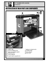
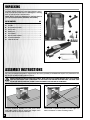
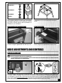
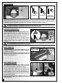
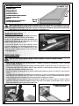
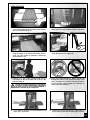
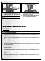
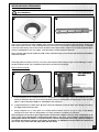
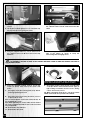
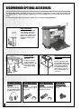
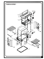
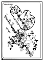
SETUP & OPERATION MANUAL FEATURES Powerful 2 HP 15 A motor with thermal overload protection. 13” PLANER WITH HELICAL HEAD Front and rear fold-down extension tables for smooth easy stock feeding. Top mounted rollers for multiple passes. Built-in inset lifting handles. Large depth of cut adjustment handle – one full rotation equals 1/16”. Easy to read thickness indicator with graduated scale in inches and metric. Safety on/off switch with key. Unit cannot be started when key is removed from switch. Depth of cut indicator. Pre-set depth stop for repeat cuts at 1/8”, 1/4”, 1/2” and 3/4”. Included dust hood has both 2 1/2” and 4” dust hose outlets. Helical head with 26 reversible two-sided carbide inserts. Cutter head supported on 4 threaded posts to ensure head stability and minimize workpiece snipe. SPECIFICATIONS • Table area with extensions (L x W) 28 5⁄8” x 13” (720 x 330 mm) • Maximum planing width 13” (330 mm) • Maximum thickness of stock 6” (152 mm) • Minimum thickness of stock 1/8” (3 mm) • Minimum length of stock 5” (127 mm) • Maximum depth of cut (full width) 1/16” (1.5 mm) • speed 9,700 RPM • Feed speed 26 FPM • Motor 2 HP, 120 V, 1 Ph, 15 A • Weight 64 LBS (29 Kg) Version #2/Revision #1 - (S/N 32349814) May 29, 2014 © Copyright General International MODEL #30-005HC MI GENERAL® INTERNATIONAL 8360 Champ-d’Eau, Montreal (Quebec) Canada H1P 1Y3 Telephone (514) 326-1161 • Fax (514) 326-5555 • www.general.ca THANK YOU for choosing this General® International model 30-005HC M1 13” Planer with Helical . This planer has been carefully tested and inspected before shipment and if properly used and maintained, will provide you with years of reliable service. For your safety, as well as to ensure optimum performance and trouble-free operation, and to get the most from your investment, please take the time to read this manual before assembling, installing and operating the unit. The manual’s purpose is to familiarize you with the safe operation, basic function, and features of this planer as well as the set-up, maintenance and identification of its parts and components. This manual is not intended as a substitute for formal woodworking instruction, nor to offer the user instruction in the craft of woodworking. If you are not sure about the safety of performing a certain operation or procedure, do not proceed until you can confirm, from knowledgeable and qualified sources, that it is safe to do so. Once you’ve read through these instructions, keep this manual handy for future reference. Disclaimer: The information and specifications in this manual pertain to the unit as it was supplied from the factory at the time of printing. Because we are committed to making constant improvements, General® International reserves the right to make changes to components, parts or features of this unit as deemed necessary, without prior notice and without obligation to install any such changes on previously delivered units. Reasonable care is taken at the factory to ensure that the specifications and information in this manual corres-ponds with that of the unit with which it was supplied. However, special orders and “after factory” modifications may render some or all information in this manual inapplicable to your machine. Further, as several gene-rations of this model of planer and several versions of this manual may be in circulation, if you own an earlier or later version of this unit, this manual may not depict your machine exactly. If you have any doubts or questions contact your retailer or our support line with the model and serial number of your unit for clarification. GENERAL®INTERNATIONAL WARRANTY All component parts of General® International and Excalibur by General International® products are carefully inspected during all stages of production and each unit is thoroughly inspected upon completion of assembly. Limited Lifetime Warranty Because of our commitment to quality and customer satisfaction, General® International agrees to repair or replace any part or component which upon examination, proves to be defective in either workmanship or material to the original purchaser for the life of the tool. However, the Limited Lifetime Warranty does not cover any product used for professional or commercial production purposes nor for industrial or educational applications. Such cases are covered by our Standard 2-year Limited Warranty only. The Limited Lifetime Warranty is also subject to the “Conditions and Exceptions” as listed below. Standard 2-Year Limited Warranty All products not covered by our lifetime warranty including products used in commercial, industrial and educational applications are warranted for a period of 2 years (24 months) from the date of purchase. General® International agree to repair or replace any part or component which upon examination, proves to be defective in either workmanship or material to the original purchaser during this 2-year warranty period, subject to the “conditions and exceptions” as listed below. To file a Claim To file a claim under our Standard 2-year Limited Warranty or under our Limited Lifetime Warranty, all defective parts, components or machinery must be returned freight or postage prepaid to General® International, or to a nearby distributor, repair center or other location designated by General® International. For further details call our service department at 1-888-949-1161 or your local distributor for assistance when filing your claim. Along with the return of the product being claimed for warranty, a copy of the original proof of purchase and a “letter of claim” must be included (a warranty claim form can also be used and can be obtained, upon request, from General® International or an authorized distributor) clearly stating the model and serial number of the unit (if applicable) and including an explanation of the complaint or presumed defect in material or workmanship. CONDITIONS AND EXCEPTIONS: This coverage is extended to the original purchaser only. Prior warranty registration is not required but documented proof of purchase i.e. a copy of original sales invoice or receipt showing the date and location of the purchase as well as the purchase price paid, must be provided at the time of claim. Warranty does not include failures, breakage or defects deemed after inspection by General® International to have been directly or indirectly caused by or resulting from; improper use, or lack of or improper maintenance, misuse or abuse, negligence, accidents, damage in handling or transport, or normal wear and tear of any generally considered consumable parts or components. Repairs made without the written consent of General® International will void all warranty. TABLE OF CONTENTS Rules for safe operation.................................... 5 Electrical requirements............................... 6 Operating Instructions....................... 11 Basic principles of planing................................................ 11 Selecting boards suitable for planing............................. 11 Grounding instructions......................................................... 6 Rated limits of this planer.................................................. 12 Circuit capacity.................................................................... 6 Checklist before starting.................................................... 12 Extension cords..................................................................... 6 Planing step-by-step........................................................... 13 Identification of main parts and components... 7 Unpacking................................................... 8 Maintenance & Adjustments............. 14 Periodic maintenance....................................................... 14 Inspecting/Replacing cutter head knives...................... 15 Replacing the v-belt........................................................... 17 Assembly Instruction............................ 8 Attach the depth of cut adjustment handle..................... 9 Attach the dust chute........................................................... 9 Basic Adjustments and Controls........ 9 Connecting to a power source.......................................... 9 On/Off power switch.......................................................... 10 Surge protection/Circuit breaker..................................... 10 Raising/Lowering the ........................................................ 11 Pre-set tickness stop gauge............................................... 11 Depth of cut indicator........................................................ 11 Drive chain/gear lubrication............................................ 17 Recommended optional accessories............18 Parts list & diagrams ................................. 19-23 RULES FOR SAFE OPERATION To help ensure safe operation, please take a moment to learn the machine’s applications and limitations, as well as potential hazards. General® International disclaims any real or implied warranty and holds itself harmless for any injury that may result from improper use of its equipment. 1. Do not operate this planer when tired, distracted, or under the effects of drugs, alcohol or any medication that impairs reflexes or alertness. 13. Do not push or force stock into the . The planer will perform better and safer when working at the rate for which it was designed. 2. The working area should be well lit, clean and free of debris. 14. 3. Keep children and visitors at a safe distance when the planer is in operation; do not permit them to operate the planer. 4. Childproof and tamper proof your shop and all ma chinery with locks, master electrical switches and switch keys, to prevent unauthorized or unsupervised use. 5. Stay alert! Give your work your undivided attention. Even a momentary distraction can lead to serious injury. 6. Fine particulate dust is a carcinogen that can be hazardous to health. Work in a well-ventilated area and whenever possible use a dust collector. Wear face, eye, ear, respiratory and body protection devices. 7. Do not wear loose clothing, gloves, bracelets, necklaces or other jewelry while the planer is in operation. Wear protective hair covering to contain long hair and wear non-slip footwear. 8. Be sure that adjusting wrenches, tools, drinks and other clutter are removed from the machine and/or the table surface before operating. 9. Keep hands well away from knives and all moving parts. Use a push stick to feed stock, and a brush, not hands, to clear away chips and dust. 10. Be sure that the knives are securely installed in the . 11. Always use clean, properly sharpened knives. Dirty or dull knives are unsafe and can lead to accidents. 12.Inspect stock and remove all foreign objects before planing. Make sure that any stock you plane is clean and free of any dirt, nails, staples, tiny rocks or any other foreign objects that may damage the planer knives. Only process natural solid wood boards. Never plane MDF, particle board, plywood, laminates or other syn thetic materials. Kickback is when the workpiece is ejected at high speeds by the force of the . To minimize the risk of injury from kickback, use proper feeding technique and stand to one side, out of the path of a potential kickback. 15.Select appropriate feed speed for the stock being planed: high speed for softwood and slow for hardwoods. 16.Place stock firmly against the table and use suitable in-feed and out-feed support if stock is too long. 17. Keep guards in place and in working order. If a guard must be removed for maintenance or cleaning make sure it is properly attached before using the machine again. 18.Use of parts and accessories NOT recommended by GENERAL®INTERNATIONAL may result in equipment malfunction or risk of injury. 19. Never stand or lean on machinery. Serious injury could result if the tool is tipped over or if the cutting tool is unin tentionally contacted. 20.Always disconnect the tool from the power source before servicing or changing accessories such as knives, or before performing any maintenance or cleaning, or if the machine will be left unattended. 21. Make sure that the switch is in the “OFF” position before plugging in the power cord. 22.Make sure the tool is properly grounded. If equipped with a 3-prong plug it should be used with a three-pole receptacle. Never remove the third prong. 23.Do not use this planer for other than its intended use. If used for other purposes, GENERAL®INTERNATIONAL disclaims any real implied warranty and holds itself harmless for any injury, which may result from that use. 5 ELECTRICAL REQUIREMENTS BEFORE CONNECTING THE MACHINE TO THE POWER SOURCE, VERIFY THAT THE VOLTAGE OF YOUR POWER SUPPLY CORRESPONDS WITH THE VOLTAGE SPECIFIED ON THE MOTOR I.D. NAMEPLATE. A POWER SOURCE WITH GREATER VOLTAGE THAN NEEDED CAN RESULT IN SERIOUS INJURY TO THE USER AS WELL AS DAMAGE TO THE MACHINE. IF IN DOUBT, CONTACT A QUALIFIED ELECTRICIAN BEFORE CONNECTING TO THE POWER SOURCE. THIS TOOL IS FOR INDOOR USE ONLY. DO NOT EXPOSE TO RAIN OR USE IN WET OR DAMP LOCATIONS. EXTENSION CORDS If you find it necessary to use an extension cord with your machine, use only 3-wire extension cords that have 3-prong grounding plug and a matching 3-pole receptacle that accepts the tool’s plug. Repair or replace a damaged extension cord or plug immediately. GROUNDING INSTRUCTIONS In the event of an electrical malfunction or short circuit, grounding reduces the risk of electric shock. The motor of this machine is wired for 120V single phase operation and is equipped with a 3-conductor cord and a 3-prong grounding plug to fit a grounded type receptacle . Do not remove the 3rd prong (grounding pin) to make it fit into an old 2-hole wall socket or extension cord. If an adaptor plug is used , it must be attached to the metal screw of the receptacle. Note: The use of an adaptor plug is illegal in some areas. Check your local codes. If you have any doubts or if the supplied plug does not correspond to your electrical outlet, consult a qualified eletrician before proceeding. CIRCUIT CAPACITY Make sure that the wires in your circuit are capable of handling the amperage draw from your machine, as well as any other machines that could be operating on the same circuit. If you are unsure, consult a qualified electrician. If the circuit breaker trips or the fuse blows regularly, your machine may be operating on a circuit that is close to its amperage draw capacity. However, if an unusual amperage draw does not exist and a power failure still occurs, contact a qualified technician or our service department. 6 Make sure the cord rating is suitable for the amperage listed on the motor I.D. plate. An undersized cord will cause a drop in line voltage resulting in loss of power and overheating. The accompanying chart shows the correct size extension cord to be used based on cord length and motor I.D. plate amp rating. If in doubt, use the next heavier gauge. The smaller the number, the heavier the gauge. EXTENSION CORD LENGTH ` AMPERES (AMPS) 25 FEET 50 FEET 100 FEET 150 FEET <5 18 16 16 14 6 TO 10 18 16 14 12 10 TO 12 16 16 14 14 12 TO 16 14 12 * NR * NR * NR = Not Recommended 13” PLANER WITH HELICAL 30-005HC M1 IDENTIFICATION OF MAIN PARTS AND COMPONENTS C D E G F B A REAR VIEW I J H IN-FEED TABLE DEPTH OF CUT INDICATOR STOCK THICKNESS SCALE OUT-FEED TABLE HEIGHT ADJUSTMENT HANDLE TOOL STORAGE RETURN ROLLERS DUST CHUTE CIRCUIT BREAKER ON/OFF SWITCH W/SAFETY KEY 7 UNPACKING Carefully unpack and remove the planer and its components from the box and check for damaged or missing items as per the list of contents below. A B NOTE: Please report any damaged or missing items to your General International distributor immediately. LIST OF CONTENTS QTY A- PLANER............................................................................1 B- ADJUSTMENT HANDLE....................................................1 C- DUST CHUTE....................................................................1 D- SAFETY KEY.....................................................................1 E- CAP SCREW....................................................................1 F- BUTTON HEAD SCREW....................................................4 G- T-HANDLE WRENCH........................................................1 H- 4 MM ALLEN KEY............................................................1 D E F C G H ASSEMBLY INSTRUCTIONS For your convenience this planer is shipped from the factory partially assembled and requires only minimal assembly and set up before being put into service. BEFORE STARTING THE INSTALLATION AND ASSEMBLY, MAKE SURE THAT THE POWER SWITCH IS IN THE “OFF” POSITION AND THAT THE POWER CORD IS UNPLUGGED. DO NOT PLUG IN OR TURN ON THE PLANER UNTIL YOU HAVE COMPLE-TED THE INSTALLATION AND ASSEMBLY STEPS DESCRIBED IN THIS SECTION OF THE MANUAL. The unit should be installed on a flat, level, sturdy and stable surface, able to support the weight of the machine and the workpiece with ease. 8 Never install or operate the planer over the edge of a table, workbench or other mounting surface. HEX HEAD BOLT (1) FLAT WASHERS (2) LOCK WASHER (1) HEX NUT (1) If a permanent shop placement or installation is practical, consider using the mounting holes and drilling matching through holes in your workbench or mounting surface to bolt the planer in place (hardware not included) on your workbench. If you prefer an optional steel stand (item #30-006) is available from your local General International dealer. ATTACH THE DEPTH OF CUT ADJUSTMENT HANDLE ATTACH THE DUST CHUTE Attach the adjustment handle on top of the machine as shown, using the supplied allen key and cap screw. Install the dust chute on the rear of the machine as shown, using the 4 supplied button head screws. BASIC ADJUSTMENTS AND CONTROLS CONNECTING TO A POWER SOURCE TO REDUCE THE RISK OF SHOCK OR FIRE DO NOT OPERATE THE UNIT WITH A DAMAGED POWER CORD OR PLUG. REPLACE DAMAGED CORD OR PLUG IMMEDIATELY. TO AVOID UNEXPECTED OR UNINTENTIONAL START-UP, MAKE SURE THAT THE POWER SWITCH IS IN THE OFF POSITION BEFORE CONNECTING TO A POWER SOURCE. C B SWITCH OFF A Once the assembly steps have been completed and the unit is safely secured or installed on a work surface such as a bench, stand or worktable, uncoil the power cord. With the switch locked-out (i.e. without the supplied safety key A installed, as shown in B, or in the off position C), plug the power cord into an appropriate outlet. Refer back to the section entitled Electrical Requirements and make sure all requirements and grounding instructions are followed. When planing operations have been completed unplug the unit from the power source. 9 ON/OFF POWER SWITCH B D C A POWER ON POWER OFF SAFETY KEY (PREVENTS START-UP WHEN REMOVED) This planer is equipped with a rocker style ON/OFF switch located on the front left hand side of the . To start the planer, insert the lock-out key as shown in A and pull up on the lower portion of the switch as shown, B. To stop the planer, push down on the switch, C. To prevent unwanted or unauthorized start-up or usage, remove the lock-out key D and store it in a safe place, out of the reach of children, whenever the planer is not in use. TO PREVENT UNWANTED OR UNAUTHORIZED START-UP OR USAGE, REMOVE THE LOCK-OUT KEY AND STORE IT IN A SAFE PLACE, OUT OF THE REACH OF CHILDREN, WHENEVER THE PLANER IS NOT IN USE.a SURGE PROTECTION/CIRCUIT BREAKER The unit is equipped with a circuit breaker located to the right of the power switch, A, to protect the motor from power surges or spikes in line voltage. In the event of a power surge, the circuit breaker will be automatically tripped thereby cutting off the power to the motor. SWITCH OFF To reset the circuit breaker after it has been tripped; set the power switch to the “off” position and depress the reset button on the circuit breaker, then restart the machine. A TO AVOID UNEXPECTED OR UNINTENTIONAL START-UP BE CERTAIN THAT THE POWER SWITCH HAS BEEN SET TO THE OFF POSITION BEFORE RE-SETTING THE CIRCUIT BREAKER. RAISING / LOWERING THE To adjust the depth of cut, the cutter head assembly can be raised or lowered as needed by rotating the depth of cut adjustment handle. 1x = 1/16” NOTE: Each full clockwise rotation of the handle will lower the cutter head by 1/16”. Each full counterclockwise rotation will raise the cutter head by 1/16”. DOWN UP PRE-SET THICKNESS STOP GAUGE B The adjustable pre-set depth gauge located on the right side of the planer, A, allows the user to select one of four commonly used workpiece final thickness settings. With the cutter head set slightly above the height of the workpiece press down and rotate the spring loaded adjustment knob to select the desired final thickness setting from either 1/8”, 1/4”, 1/2” & 3/4”. This will set the stop pin to prevent the cutter head from going any lower than the selected thickness, B. A NOTE: Once you have planed the workpiece down to the selected thickness, do not attempt to lower the cutter head further. Forcing the depth of cut handle when the cutter head has bottomed out on the pre-set stop pin will damage the raising mechanism. 10 DEPTH OF CUT INDICATOR The depth of cut indicator, A, will indicate how much material the cutter head is set to remove from the workpiece for a given pass. A The pointer will read zero until the workpiece engages the front of the cutter head. Place the workpiece under the front of the cutter head and turn the height adjustment handle clockwise until the cutter head makes contact with the workpiece & until the depth of cut indicator shows the reading that matches the desired cut. Failure to follow these recommendations will lead to premature blade wear and may cause premature motor failure. It is recommended that for both hard and soft wood: For stock up to 6” in width, never remove more that 1/8” per pass, A. For stock of 6”-13” in width, never remove more than 1/16” per pass, B. A B 1/8” or less 1/16” or less Removing less material per pass and taking multiple passes is always preferred to more aggressive planing. Advantages include longer blade life, better finish quality (resulting in less time sanding later) and less likelihood of removing too much material causing the workpiece to be too thin for its intended use. OPERATING INSTRUCTIONS BASIC PRINCIPLES OF PLANING This thickness planer is designed to remove material from the top face of a board in order to bring the board (or a series of boards) down to a specific desired thickness. A To obtain even, uniform thickness across the length of a board, the stock being planed must have one face that has already been machined perfectly flat (usually on a jointer) and the stock should be fed with this flat face against the table, A. FLAT SIDE DOWN If it is not possible to machine one face perfectly flat before planing, take shallow passes all on the same face of the board until this face has been machined level. Then the board should be flipped over and the leveled face should be fed face down against the table to allow you to dimension the board to final thickness. SELECTING BOARDS SUITABLE FOR PLANING This planer is not intended (and should not be used) to plane any material other than solid wood. The workpiece should always be fed through the planer in the general direction of the grain in the wood, B. B GRAIN DIRECTION AIN GR E DIR N IO CT Before being fed through the planer all lumber should be inspected for debris and foreign objects such as staples or nails. Foreign objects stuck to, or embedded in your workpiece can be ejected from the machine at high speed and cause serious injury or damage cutter knives. Make sure to remove all such foreign objects from the wood before running it through the planer. Select lumber carefully and avoid workpieces with loose or protruding knots. Workpieces that are twisted, severely deformed or warped should also be avoided. Warped, twisted, damaged or fragile stock runs an increased risk of jamming in or damaging the machine or cutters. There is also a much greater risk of injury to the operator or bystanders from kickback, where the workpiece is forcefully or violently ejected from the machine due to a jam, whenever working with such damaged or warped wood. 11 RATED LIMITS OF THIS PLANER Max. 13” THE MAXIMUM PLANING WIDTH OF THIS UNIT IS 13”. THE MAXIMUM WORKPIECE THICKNESS OF THIS UNIT IS 6” THE MINIMUM THICKNESS TO WHICH A WORKPIECE CAN BE SAFELY PLANED WITH THIS UNIT IS 1/8” . THE MINIMUM WORKPIECE LENGTH THAT CAN BE SAFELY PLANED WITH THIS UNIT IS 5”. Min. 5” Min. 1/8” Max. 6” RESPECT THE RATED LIMITS OF THIS MACHINE IGNORING THESE LIMITS AND FEEDING NON COMPATIBLE STOCK INTO THIS PLANER CAN LEAD TO SERIOUS INJURY TO THE USER OR SHOP BYSTANDERS, AND CAUSE DAMAGE TO THE WORKPIECE AND/OR THE MACHINE. IF THE STOCK YOU WISH TO PLANE DOES NOT MEET OR COMPLY WITH THE LIMITATIONS LISTED ABOVE, FIND ANOTHER SAFER WAY TO PERFORM THE REQUIRED TASK. CONNECTING TO A DUST COLLECTOR A dust port A with a 4” opening is provided to accommodate connection to a dust collector (not included). Be sure to use appropriate sized hose and fittings (not included) and check that all connections are sealed tightly to help minimize airborne dust. If you do not already own a dust collection system consider contacting your General® International distributor for information on our complete line of dust collection systems and accessories or visit our Web Site at www.general.ca A CHECKLIST BEFORE STARTING VERIFY ALL CHECK POINTS BEFORE STARTING. FAILURE TO COMPLY CAN RESULT IN SERIOUS INJURIES. • Make sure the board has been inspected and is suitable for planing as explained in section “Selecting boards suitable for planing”. • Make sure you and any assistants are wearing safe appropriate workshop attire. Roll up long sleeves, secu re long hair and remove any jewelry: watches, rings, bracelets or anything that could become caught in the moving parts, potentially causing serious injury. • Make sure to have on safety glasses as well as hearing and respiratory protection at all times when using the planer. • To reduce the risk of damage to the planer or the workpiece, as well as a potential for personal injury, after ini tial set-up as well as before each use, make sure that everything is securely installed and that all fasteners and moving parts on this machine are locked in placebefore starting the machine. • If multiple boards are to be planed, collect all workpieces together and set them nearby on a table or bench within easy reach A. To limit the potential for injury in the event of a kickback, avoid having to step or reach in front of the machine to pick up the next workpiece B. A AVOID HAVING TO STEP OR REACH IN FRONT OF THE MACHINE. B 12 PLANING STEP-BY-STEP 1. With the planer turned off, position the workpiece on the infeed table with the flat face down and the face to be planed facing up. 2. If a specific pre-set thickness is required, set the depth stop to the desired final workpiece thickness. A B 3. Slide the workpiece up to the cutter head and using the depth of cut adjustment handle, raise or lower the cutter head as needed to obtain the desired depth of cut. 4. Set the board aside, then insert the safety key in the switch A and turn on the planer B. 5. Stand to one side of the machine and set the board back on the infeed table with the face to be planed facing up. 6. Align the board laterally so that it will be fed through the planer in the general direction of the grain, and allow the workpiece enough clearance to feed properly without rubbing or catching on either side of the machine.| TO LIMIT THE POTENTIAL FOR INJURY IN THE EVENT OF A KICKBACK, AVOID STANDING DIRECTLY IN LINE WITH THE FRONT OR BACK OF THE PLANER WHENEVER A BOARD IS ENGAGED IN THE CUTTER HEAD. 7. Slowly slide the workpiece forward until the infeed roller “grips” the board. 8. Release the board allowing the feed roller to automatically feed the board through the planer. 13 9. Step to the rear of the machine and recover the planed board on the outfeed table once it has cleared the outfeed roller and has stopped advancing. NEVER PUSH, PULL OR OTHERWISE TRY TO MOVE OR RE-POSITION THE WORKPIECE ONCE IT IS IN THE CONTROL OF THE AUTOMATIC FEED ROLLERS. 10. The return rollers on the top of the planer can be used to pass the workpiece back to the front of the machine for repeat passes. 11. Repeat these steps as needed for all boards that need to be planed to the same thickness. MAINTENANCE AND ADJUSTMENTS PERIODIC MAINTENANCE MAKE SURE THE PLANER HAS BEEN TURNED OFF AND UNPLUGGED FROM THE POWER SOURCE BEFORE PERFORMING ANY MAINTENANCE OR ADJUSTMENT. • Inspect/test the ON/OFF switch before each use. Do not operate the planer with a damaged switch; replace a damaged switch immediately. • Keep the machine as well as the in-feed out-feed tables clean and free of saw dust, woodchips, pitch or glue. Vacuum or brush off any loose debris and wipe down the machine and the tables occasionally with a damp rag. • An occasional light coating of paste wax can help protect the tables’ surface and reduce workpiece friction. Ask your local distributor for suggestions on aftermarket surface cleaners, protectant and dry lubricants based on what is readily available in your area. • Avoid using silicon based products that may affect wood finishing products such as oil, solvent or water-based stains, varnishes and lacquers. • Periodically inspect the power cord and plug for damage. To minimize the risk of electric shock or fire, never operate the planer with a damaged power cord or plug. Replace a damaged power cord or plug at the first visible signs of damage. • The motor and cutter head bearings are sealed and permanently lubricated – no further lubrication is required. • The drive gears, chain and elevation screws should be cleaned of woodchips, dust, debris and old grease after every 10-15 hours of use. After cleaning, re-apply a generous coating of any common automotive bearing grease. • Regularly inspect planed workpieces for signs of knife damage or wear and replace damaged or worn knives immediately. 14 INSPECTING/REPLACING CUTTER HEAD KNIVES MAKE SURE THE PLANER HAS BEEN TURNED OFF AND UNPLUGGED FROM THE POWER SOURCE BEFORE PERFORMING ANY MAINTENANCE. A B There are 26 reversible two-sided cardide inserts (knives) A installed in the helical B at the factory. With usage and normal wear over time, it will eventually become necessary to reverse and/or replace the inserts. To maintain even insert wear always reverse all 26 inserts each time knife replacement is required. If one of the inserts has been nicked or damaged on one of it’s edges, it can be simply reversed instead of replaced. When needed, replacement carbide inserts B can be ordered through your local General International distributor under item #30-006. Observing planed workpieces as they come out of the machine and looking for signs of knife damage or wear is the best method to help you to determine when knives are due to be changed. Signs to look for include: A B EFFECT EXAGGERATED FOR CLARITY 1. A raised ridgeline in the workpiece that runs a straight line from beginning to end of the board, A. This is ge nerally an indication that one of the knives has been nicked or damaged by a foreign object such as a nail, staple or other hard object hidden or embedded in the workpiece. 2. A slight washboard or chatter effect, B, which can be an indication of uneven knife wear causing one knife to cut slightly deeper than the other. 3. Rough, irregular, torn or fuzzy grain on a freshly planed surface may be a sign of worn or dull blades causing the wood to tear out. Sharp blades cut crisply and leave a relatively smooth finish. Note: Fuzzy grain can also be a sign of high moisture content in the workpiece. If knives have recently been changed or if you suspect that moisture content and not dull knives is the cause, set the workpiece aside and test by planing other boards with known or acceptable moisture content. If the planed results using a different workpiece are smooth, then moisture content in your wood is the problem - no adjustments can be made to the machine for this. Set the “wet” stock aside and simply work with drier wood. 15 A 1. Turn off and unplug the machine from the power source. 2. Set the pre-set depth gauge to 3/4” so that the stop pin prevents the from going any lower. 3. Using the supplied allen key, loosen and remove the 4 button head screws A, and remove the dust chute. B 4. Using the supplied allen key, loosen and remove the 2 button head screw B, then remove the chip deflector. 5. Insert the supplied allen key into the hole on the side of the planer as shown to keep the from turning while changing knives. NEVER RUN A FINGER OR OTHER BODY PART ALONG THE CUTTING EDGE OF THE KNIFE TO TEST FOR SHARPNESS OR TO DETERMINE IF THE EDGE IS WORN OR HAS ALREADY BEEN USED. FAILURE TO HEED THIS WARNING CAN LEAD TO SERIOUS INJURY. D C E Important! To prevent knife height discrepencies, the inserts and screws must be clean and free of debris. <?> 6. Using the supplied t-handle wrench, loosen the screws as shown, then remove the screws and inserts. 7. Thoroughly clean the housing and cavity before reversing/replacing an insert. 9. Place the insert in the housing and firmly secure it in place with a screw. Note: To avoid stripped screws and cracked inserts, do not overtighten the screws Note: When tightening the screws, make sure the head of the screw is aligned flush with the hole of the insert and does not protrude. 10. Re-install the chip deflector. 11. Re-install the dust chute. 16 8. Thoroughly clean the inserts C and screws D using a lacquer thinner and small brush then apply a light coating of machine oil on the screws, taking care to remove any excess. Tip: When reversing the inserts in the , refer to the etched mark E on the inserts to keep track of the rotations. REPLACING THE V-BELT The is driven by a flat ribbed belt that is located on the right-hand side of the planer facing the infeed side. MAKE SURE THE PLANER HAS BEEN TURNED OFF AND UNPLUGGED FROM THE POWER SOURCE BEFORE PERFORMING ANY MAINTENANCE. 1.Using a 4 mm Allen wrench, remove the 5 button head cap screws holding the right hand side cover on. Lift the cover upwards slightly while pulling the bottom outwards until it is off of the machine. 2. Using a phillips screwdriver, remove the 2 phillips head screws holding the belt guard in place. 3. Roll the belt off of the pulleys by spinning the larg er pulley and pulling the belt off of the smaller pul ley one rib at a time until it is free from the pulleys. 4. Install the replacement belt in the reverse order of removal. 5. Re-install the belt guard. 6. Re-install the right hand side cover. DRIVE CHAIN/GEAR LUBRICATION H Periodically the drive chain & gears G and elevation screws H will need to be cleaned and greased to help maintain smooth feeding and contribute to longer machine life and trouble free operation. H To clean and grease the drive chain & gears and elevation screws: 1. Turn off and unplug the machine from the power source. G 2. Unfasten the 5 screws holding the frame cover in place and remove frame cover. 3. Unfasten the 2 screws holding the drive chain/gear cover in place and remove the drive chain/gear cover, I. I 4. Remove old grease and dust deposits by wiping with a dry rag. 5. Apply generous dabs of any common automotive bearing grease to the gears & chain, G and four elevation screws H. 6. Re-install the chain/gear cover and frame cover. 17 RECOMMENDED OPTIONAL ACCESSORIES We offer a large variety of products for increased convenience, productivity, accuracy and safety when using your planer. Here’s a small sampling of optional accessories available from your local General International dealer. For more information about our products, please visit our website at www.general.ca DUST COLLECTORS We offer a wide selection of top quality dust collectors to suit all your shop needs. Dust collectors contribute to a cleaner more healthful workshop environment. ROLLER STANDS #50-150, #50-170 & #50-167S HEAVY DUTY OPEN BASED STEEL STAND #30-006 We offer a selection of roller stands for added in-feed or outfeed support when working with longer stock. 18 Easy to assemble, wide based stable design with mounting slots for permanent planer installation. Foot print measures 33” (833) x 24 1/2”. Floor to top of stand height: 28” (711mm)./ ELECTRONIC EARMUFFS - #99-200 REPLACEMENT INSERTS #30-006 REPLACEMENT INSERTS #30-007 SET OF TEN M5 SCREWS #30-008 Highly efficient noise reduction to help protect your hearing when operating power tools. Reversible two-sided carbide inserts (sold in sets of ten). Reversible two-sided high speed steel inserts (sold in sets of ten). For items: 30-007. 30-006 & FRAME ASSEMBLY 1 2 12 13 8 8 11 9 34 15 16 17 55 10 14 54 53 19 6 15 14 13 5 12 11 4 10 9 20 8 3 7 6 2 5 4 3 1 2 1 0 0 21 26 24 25 8 22 23 28 29 30 31 32 27 33 34 35 45 41 42 43 44 17-1 36 37 38 39 40 46 47 48 49 50 51 8 52 19 N MAIN ASSEMBLY 20 PARTS LIST 30-005HC M1 PART N0. REF. N0. DESCRIPTION SPECIFICATION QTY 1 2 8 9 10 11 12 13 14 15 16 17 17-1 19 20 21 22 23 24 25 26 27 28 29 30 31 32 33 34 35 36 37 38 39 40 41 42 43 44 45 46 47 48 49 50 51 52 53 54 55 56 57 58 59 60 30005-01 30005-02 30005-08 30005-09 30005-10 30005-11 30005-12 30005-13 30005-14 30005-15 30005-16 30005-17 30005-17-1 30005-19 30005-20 30005-21 30005-22 30005-23 30005-24 30005-25 30005-26 30005-27 30005-28 30005-29 30005-30 30005-31 30005-32 30005-33 30005-34 30005-35 30005-36 30005-37 30005-38 30005-39 30005-40 30005-41 30005-42 30005-43 30005-44 30005-45 30005-46 30005-47 30005-48 30005-49 30005-50 30005-51 30005-52 30005-53 30005-54 30005-55 30005-56 30005-57 30005-58 30005-59 30005-60 HANDLE ASSEMBLY CAP SCREW BUTTON HEAD SCREW TOP COVER SHAFT BUSHING UPPER BEARING SEAT RETURN ROLLER ROLLER SEAT LIFTING HANDLE SPACER SET SCREW UPPER ELEVATION NUT FLANGE NUT SIDE PANEL (RIGHT) THICKNESS SCALE HEIGHT ADJUSTMENT LEAD SCREW CAP SCREW PRE-SET STOP DIAL STEEL BALL SPRING MAIN TABLE LEAD SCREW PHILLIPS HEAD SCREW RIGHT GUIDE PLATE BASE HEX. HEAD BOLT HEX. NUT FLAT WASHER SPINDLE BEARING BEARING SEAT BUTTON HEAD SCREW FLAT WASHER SPINDLE SPROCKET FLAT WASHER CAP SCREW LEFT GUIDE PLATE IDLE WHEEL ECCENTRIC BUSHING CAP SCREW SIDE PANEL - LEFT PHILLIPS HEAD SCREW TABLE SUPPORT BRACKET LOCK WASHER TABLE BUSHING PHILLIPS HEAD SCREW TABLE EXTENSION ELEVATION CHAIN HEX HEAD BOLT HEX NUT FLAT WASHER BELT GUARD BELT L.H. HEX NUT DRIVE PULLEY BUTTON HEAD SCREW M5xP0.8x20L M6xP1.0x8L M5xP0.8x5L M6xP1.0 M6xP1.0 Ø10 Ø7.62xØ15.75x0.7t M4xP0.7x10L M6xP1.0x20L M6xP1.0 Ø12.2xØ25.8x2t 6000ZZ M5xP0.8x12L Ø10.3xØ18x1t Ø4.2xØ15x2t M4xP0.7x12L M5xP0.8x25L M4xP0.7x6L TP305 M6xP1.0x16L #410, 100 M8xP1.25x45L M8xP1.25 140 J6 M16xP2.0L.H. M5xP0.8x12L 1 1 15 1 3 1 2 4 2 1 1 4 4 1 1 1 1 1 1 1 1 3 4 1 1 4 4 4 5 4 10 4 4 4 4 1 2 2 2 1 12 4 4 4 4 2 1 1 1 4 1 1 1 1 11 21 PARTS LIST 30-005HC M1 PART N0.REF. N0.DESCRIPTION 22 61 30005-61 62 30005-62 63 30005-63 64 30005-64 6530005-65 66N 30005-66N 67 30005-67 68 30005-68 69 30005-69 70 30005-70 72 30005-72 73 30005-73 74 30005-74 75 30005-75 76 30005-76 77 30005-77 78 30005-78 79 30005-79 80 30005-80 81 30005-81 82 30005-82 83 30005-83 84 30005-84 85 30005-85 86 30005-86 95 30005-95 96 30005-96 97 30005-97 98 30005-98 99 30005-99 100 30005-100 112 30005-112 11330005-113 114 30005-114 115 30005-115 116 30005-116 117 30005-117 118 30005-118 119 30005-119 120 30005-120 121 30005-121 122 30005-122 123 30005-123 125 30005-125 127 30005-127 150 30005-150 151 30005-151 152 30005-152 153 30005-153 154 30005-154 155 30005-155 156 30005-156 157 30005-157 158 30005-158 159 30005-159 160 30005-160 SPECIFICATION QTY BEARING SEAT 1 BEARING 6203ZZ 2 BEARING RETAINER 1 PHILLIPS HEAD SCREW M3xP0.5X8L 2 KEY 5x5x12mm 1 HELICAL CUTTER HEAD 1 CARBIDE INSERTS (see #30-006 - set of 10 inserts) 14 x14 x 2 mm 26 TORX SCREW (see #30-008) M5 x P0.8 26 TORX WRENCH 1 ALLEN WRENCH 4x120mmL 1 CHIP BREAKER 1 POWER CORD CLAMP GCL 5/16 S 1 DUST CHUTE 1 BUTTON HEAD SCREW M6xP1.0x10L 2 CHIP DEFLECTOR 1 UPPER FRAME 1 SET SCREW M5xP0.8x6L 8 PINION 1 BUTTON HEAD SCREW M6xP1.0x12L 6 MOTOR MOUNTING PLATE 1 POINTER 1 PHILLIPS HEAD SCREW M3xP0.5x16L 2 PHILLIPS HEAD SCREW M5xP0.8x8L 2 EXT TOOTH WASHER Ø5 2 PHILLIPS HEAD SCREW M4xP0.7x12L 3 DEPTH OF CUT INDICATOR 1 MOTOR PIVOT ROD 1 BUTTON HEAD SCREW M5xP0.8x16L 2 FLAT WASHER Ø8.4xØ18x2t 1 BUTTON HEAD SCREW M8xP1.25x20L 1 GEAR BOX ASSY 1 CAP SCREW M5xP0.8x35L 2 SPROCKET 8T 4 CIRCLIP STW15 3 GEARBOX DRIVE CHAIN #410, 27 2 SPONGE 1 GEARBOX GUARD 1 CAP SCREW M5xP0.8x40L 2 SPROCKET SPACER 1 OUTFEED ROLLER 1 SPRING 4 BEARING BLOCK 4 BEARING BLOCK RETAINER 4 INFEED ROLLER 1 PHILLIPS HEAD SCREW W/WASHER M4xP0.7x8L 2 MOTOR ASSY 1 STRAIN RELIEF BUSHING HALO(6P3-4) 1 PHILLIPS HEAD SCREW M5xP0.8x40L 1 FAN HOUSING 1 SPONGE GASKET 1 WARNING LABEL (UL) 1 PHILLIPS HEAD SCREW M5xP0.8x50L 1 PHILLIPS HEAD SCREW M4.8xP1.2x16L 4 PHILLIPS HEAD SCREW M5xP0.8x8L 1 SPROCKET WASHER M5 1 GROUND WIRE 300mm +/- 3mm± 1 PARTS LIST 30-005HC M1 PART N0. 161 162 163 164 165 166 167 168 169 170 171 172 173 174 175 176 177 178 179 180 181 182 183 REF. N0. DESCRIPTION 30005-161 MOTOR FAN COVER 30005-162 WAVE WASHER 30005-163 BEARING 30005-164 ARMATURE 30005-165 SLEEVE 30005-166 POWER CORD CLAMP 30005-167STATOR 30005-168 PHILLIPS HEAD SCREW 30005-169 MOTOR HOUSING 30005-170 SET SCREW 30005-171 RETENTION RING 30005-172 BRUSH HOLDER 30005-173 MOTOR BRUSH 30005-174 BRUSH CAP 30005-175 INSULATOR 30005-176 SWITCH COVER 30005-177 PHILLIPS HEAD SCREW 30005-178 SWITCH 30005-179 SWITCH KEY 30005-180 CIRCUIT BREAKER CONNECTING WIRE 30005-181 NAME PLATE 30005-182 CIRCUIT BREAKER RESET 30005-183 POWER CORD (UL/CSA) SPECIFICATION QTY 6201 LLB GCL5/16S 120V/60Hz M4.8x75L M5xP0.8x8mmL RTW32 TP305 TP305 3/16»x3/8»L HT-18 ¨ı 20A,A-0701 14AWG,120V,2.4mL 1 1 2 1 1 1 1 2 1 2 1 2 2 2 1 1 4 1 1 1 1 1 1 NOTES 23 MODEL 30-005HC M1 8360 Champ-d’Eau, Montreal (Quebec) Canada H1P 1Y3 Fax: (514) 326-5565 - Tel.: (514) 326-1161 Fax: (514) 326-5555 - Parts & Service / Order Desk [email protected] www.general.ca IMPORTANT When ordering replacement parts, always give the model number, serial number of the machine and part number. Also a brief description of each item and quantity desired.í