1
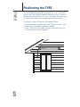
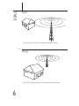
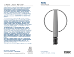
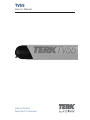
TV55
Owner’s Manual
Indoor/Outdoor
Amplified TV Antenna
Safety Precautions
TV55
Warning!
Use extreme caution when installing or removing an outdoor
antenna that is located close to overhead wires such as power
lines, telephone lines or cable TV lines. If any part of the antenna
makes contact with overhead power lines, touching the antenna
or the antenna cable can cause electrocution and death. If the
antenna is in contact with any type of overhead wires, call your
power company and ask them to send a qualified technician to
remove the antenna. Do not attempt to remove it yourself!
Important Safety Precautions...
Many do-it-yourself and professional antenna installers are
injured or killed each year by electric shock. While anyone can see
the obvious danger of falling, the most resourceful sometimes fail
to recognize overhead wires as being potentially lethal. To touch
any part of the antenna to these overhead wires is the same as
touching the wires with your bare hand. A very serious shock is
almost sure to result when contacting an electrical wire, and in
the case of primary wires on the top of poles, the shock is like
being struck by a bolt of lightning. Many power wires are within 20
to 25 feet of the ground and could easily be touched by an
assembled antenna.
1
TV55
Please read and follow these important safety precautions:
• Be sure to select an antenna site well away from all overhead wires.
• Do not try to guess which overhead wires carry high voltage.
Check with the Power Company.
• If you notice anything making contact with the overhead wires,
call the Power Company to have it removed safely. Do not run
the downlead cable over power wires.
• Get help from a qualified professional when removing the old
antenna if there is any doubt of clearing overhead wires.
• Never install the antenna outdoors at night, when it is windy, or
during rain or snow.
• Make sure the antenna installation is secure.
• Do not stand on, lean on, hang from or hang anything on the
antenna once it is mounted.
Lightning Protection and Grounding
Always plug your TV and other electronics devices into a quality
surge protector for maximum protection against lightning and
power surges.
• Do not run the downlead cable over power wires.
• Make sure the antenna downlead is connected to suitable
lightning arrestors.
All outdoor antenna installations should be properly grounded. To
effectively protect the installation, the coaxial cable(s) should be
grounded before they enter the house. The grounding of
the coaxial cable is made using a “ground block” and copper
wire (not supplied). For information and the materials
needed to ground your antenna installation, visit your local
electronics store.
If you are not sure how to install the grounding block and rod,
please consult your local retailer or TERK’s Technical Support
Department at 1-800-290-6650.
2
About Your New TERK
TV55 Antenna
TV55
Your TERK TV55 antenna is designed for both single and multifamily homes. It’s specifically engineered to provide superior
reception of high-definition (HDTV), digital television (DTV) and
VHF/UHF TV channels in most viewing locations. The TV55’s unique
antenna technology and patented Dual-Mode integrated powered
amplifier produce the clearest, cleanest signals available from a
compact, unobtrusive design that blends well with any home decor.
The TV55’s weatherproof, hermetically sealed housing offers ultrareliable performance year after year. No assembly of the antenna
is required. The TV55 comes with all necessary mounting hardware
for flexible placing indoors or outdoors.
Your TV55 Antenna Includes:
(1) TV55 Amplified Antenna
(1) Power injector with 110vAC to DC power adapter
(1) Mast Mount Base
3
(1) Mast Mount Cover
TV55
(2) Window Mount Brackets
(2)-piece assembly consisting of:
(1) Window Frame Bracket
(1) Channel Insert Bracket)
(2) Wall-Mount Cam-locks
(1) 7.5" Channel Insert
(1) 36" RG6 coaxial cable
(1) 9 3/4" Flat coaxial cable
(2) #10 Plastic wall anchors
(2) #8 Plastic wall anchors
(1) 1/4-20 x 1 1/2" Hex-head bolt
(1) 1/4-20 x 2 1/2" Hex-head bolt
(2) 1/4-20 x 3/4" Hex-head bolts
(1) 1/4-20 Wing nut
(2) 1/4" - 20 Hexagon nuts
(2) #10 x 2 1/2" Flat-head screws
4
(2) #8 x 1 1/2" Pan-head screws
(2) 1/4" Split washers
Positioning the TV55
TV55
The TV55 MUST be mounted horizontally (See Fig 1.); with the
front of the TV55 facing the general direction of the TV station’s
broadcasting transmitters. See Fig 2. The higher the elevation of
the antenna, the better the reception performance will be.
Pointing the Antenna Towards the Broadcast Tower
1. Go to www.terk.com and click on the “Antenna Locator” link.
2. Enter your home address and then “Submit.”
3. Click “View Street Level Map” to see in which direction you
should face your antenna towards.
Fig 1.
5
TV55
Right
On the side of the house facing the broadcast tower
Fig 2.
Wrong
Not on the side of the house facing the broadcast tower
6
Mounting the TV55 Antenna
TV55
Mounting Options:
The TV55 can be mounted in many ways both indoors (such as on
a wall or in an attic) and outdoors (such as on a mast, on a wall,
or either under a window or a roof’s eave). Decide where you will
mount the TV55 and follow the appropriate directions.
Indoors/Outdoors using Wall Mount Brackets
Indoors
Select a spot in your home where the antenna may be positioned
horizontally and out of the way of large metal objects which may
cause interference. Be sure the antenna is not in a position where
it could easily fall or be damaged.
Note: Never install the antenna onto a metal surface. This will
seriously degrade reception quality.
Do not mount the antenna indoors if you have stucco walls or
aluminum siding.
Outdoors
Your TV55 antenna may also be mounted outdoors - on a roof’s
eave or outside a window. Mount the antenna away from trees or
other obstructions, as higher frequencies may be affected by
these obstructions.
Note: Mounting the antenna on aluminum siding or any metal
surface will greatly degrade reception. For the optimum
performance, mount the antenna horizontally, with the front
aiming at the general direction of the TV station’s broadcasting
transmitters. The higher the antennas elevation, the better the
reception performance will be.
Warning! Never hang anything from or attach any weight to the
mounting brackets or the antenna.
1. Locate:
(2) Wall-Mount Cam-locks
(2) #10 plastic wall anchors
7
2. Mark the mounting surface
you have chosen. Make a
pencil mark approximately
11" in from one end of the
antenna. Along a level
horizontal line, make a
second mark 23" from
the first.
See Fig 3.
Fig 3.
23"
11"
TV55
3. Use the #10 screws and plastic anchors to secure each of the
Wall-Mount Cam-lock units into the wall at the marks made in
Step #2. (As an alternative mounting method, you may choose
to use longer screws directly attached into wood supports, wall
studs, or use a different wall-anchoring device.) Make sure the
Cam-lock wings are vertical. See Fig 3.
4. Carefully position the TV55 antenna so that the Cam-locks slide
into the channel on the rear of the antenna. See Fig 4.
5. Once the Cam-locks are in the channel properly, turn the Camlocks 1/4-turn to secure the antenna. Do not turn these more
than necessary to lock into the antenna and secure it snugly.
See Fig 5.
Note: If the Cam-locks do not lock securely, you may need to
adjust the location of the Cam-locks along the channel.
6. Skip to the “Connecting the TV55 Antenna to a TV” section to
finish installation.
Fig 4.
8
Fig 5.
Mounting the TV55 Antenna (continued)
TV55
Outdoors using Window Mounting:
1. Locate:
(1) Channel Insert
(2) 3/4" bolts
(2) Hex-head nuts
(2) Split washers
(2) Window Mount Brackets
Plastic anchors and screws
(depending on the material being mounted to)
2. Break the Channel Insert into 2 pieces at the score line.
See Fig 6.
Note: Do not break Channel Insert if mounting on a mast. See
the “Mast Mounting” section.
Fig 6.
9
TV55
3. Insert a hex-head bolt into each of the Channel Inserts. Insure
that the bolt head fits into the hexagon recess on the insert.
4. Slide the Channel Inserts into the channel on the back of the
TV55 - the bolts should be pointing away from the antenna.
See Fig 7.
Fig 7.
5. Unscrew the Window Mount Bracket so you can separate the
two pieces (Channel Insert Bracket and Window Frame Bracket)
– keep the screw since you will need to use it again.
6. Attach the Channel Insert Brackets onto the channel insert bolt
on the TV55. See Fig 8. Tighten with split washers and hex nuts.
Fig 8.
10
Mounting the TV55 Antenna (continued)
TV55
7. Determine the location on the window where the TV55 will
be mounted.
8. Attach the Window Frame Brackets to the window. Be sure the
brackets are level and line up with the channel inserts already
on the antenna.
9. Insert the Channel Insert Brackets attached to the antenna
into the slots on the Window Frame Brackets already mounted
on the window. Reattach the brackets with the screw removed
earlier. See Fig 9.
Fig 9.
10. Skip to the “Connecting the TV55 Antenna to a TV” section
to finish installation.
11
TV55
Outdoors using Mast Mounting:
1. Locate:
(1) Channel Insert
(1) Mast Mount Base and Cover
(1) 1 1/2" hex-head bolt
(1) 2 1/2" hex-head bolt
(1) Hex nut
(1) Wing nut
2. Insert both hex-head bolts into
the Channel Insert at the hex-head recess. Slide the Channel
Insert into the channel on the back of the TV55. The bolts should
be pointing away from the antenna. See Fig 10.
Fig 10.
3. Take the Mast Bracket Base and insert it over the bolts on
the Channel Insert, with the
1 1/2" bolt closest to the hinge. Center the Mast Bracket on the
TV55. Secure and tighten the 1 1/2" bolt with a hex nut. Do not
over tighten. See Fig 11.
Fig 11.
12
Mounting the TV55 Antenna (continued)
TV55
4. Determine mast size. The supplied Mast Bracket will fit
a 1 1/4" or 1 1/2" mast. If the mast being used is 1 1/2" in
diameter, the tabs on the Mast Bracket Cover needs
to removed using a pair of pliers. See Fig 12.
Fig 12.
5. Attach the Mast Bracket Cover
to the Mast Bracket Base by inserting at the hinge.
6. Place the Mast Bracket at the desired height on the mast.
7. Close the cover and secure the 2 1/2" bolt with the wing
nut. Do not over tighten. See Fig 13.
Fig 13.
8. Skip to the “Connecting the TV55 Antenna to a TV” section to
finish installation.
13
Connecting the TV55 to a TV
TV55
1. Run the RG6 coaxial cable from the antenna towards your
television set and connect the RG6 coaxial cable to the supplied
Power Injector on the terminal labeled “TO ANTENNA”.
2. Connect the “TO TV” lead on the power injector to the “ANT IN”
on your TV.
3. Plug the Power Adapter from the Power Injector into a standard
AC outlet. Switch the Power Injector “ON” for amplification.
See Fig 14.
Fig 14.
TO TV
Splitting the Signal to Multiple TV’s
Follow the diagram to use the
TV55 with more than one TV.
A splitter will be required
sold separately).
14
NOTE: The Power Injector
MUST be installed between
the TV55 and the splitter.
Failure to do so could cause
a short circuit. The Power
Injector should always be
located indoors.
TO TV 1
TO TV55
BSP-2
Splitter
(such as the
Terk BSP-2)
TO TV 2
Running Cable
TV55
Under a Window:
1. Connect one end of the supplied RG6 coaxial cable to the “F”connector output on the end of the TV55 and connect the other
end to the 9 3/4" white flat cable.
Note: If the supplied RG6 Coaxial Cable is not long enough, you
can purchase additional lengths of RG6 Coaxial Cable from the
retailer you purchased the TV55 antenna from.
2. Run the white flat cable through an open window. Make sure
that it runs under the window to ensure proper window closure
See Fig 15.
Fig 15.
Run a coaxial cable (not supplied) from the inside end of the 93/4”
white flat cable towards your television set and connect the
coaxial cable to the supplied Power Injector on the terminal
labeled “TO ANTENNA”.
Through a Wall:
If you do not use the supplied 9 3/4" white flat cable to run your
coaxial cable through a window and instead choose to drill
through an external wall, be careful to avoid contact with any
power lines, telephone lines, cable TV lines or plumbing.
1. Connect one end of the supplied RG6 coaxial cable to the “F”connector output on the end of the TV55.
Note: If the supplied RG6 Coaxial Cable is not long enough you
can purchase additional lengths of RG6 Coaxial Cable from the
retailer you purchased the antenna from.
2. Drill a hole in an exterior wall matching the diameter of the
RG6 coaxial cable
15
3. Run the RG6 Coaxial Cable through the hole into the home.
Note: Please see “Water Damage Prevention” for proper sealing
of the hole.
TV55
Water Damage Prevention:
At the point where your coaxial cable lead enters the house, you
should allow for some slack in the coaxial cable as a “drip loop.”
This will prevent moisture from running down the coaxial cable
and entering the house.
Run the coaxial cable approximately six inches below the wall
entry point and then turn it upwards towards this spot. See Fig 16.
Any moisture that accumulates on the coaxial cable will drip off in
the bend instead of running into the house. You should seal the
point where the cable enters your home with a rubber weather
insulator or silicone caulking (not included) An “F” connector wall
plate can be used inside the home to cover the inside portion of
the whole. You can typically find an “F” connector wall plate at
any local Electronics or Hardware store.
Fig 16.
16
For Use With a Satellite Dish
TV55
TV55 Installation Procedure for use with a Satellite Dish
If you have a satellite dish it is possible to install the TV55 using
the same wiring as the satellite dish. To do this you will need to
purchase a set of diplexers (Terk model BDS-P1). The instructions
listed below are for a basic satellite system. If you have a more
complex satellite system and wish to install the TV55 in this
manor please call TERK Support at 1-800-290-6650.
Note: THE POWER-INJECTOR SHOULD NOT BE INSTALLED
WHEN USING A SATELLITE SYSTEM WITH THE TV55.
1. Disconnect the coaxial cable from your satellite dish’s LNB.
2. Reconnect this coaxial cable to the outdoor diplexer on the
terminal labeled “SAT/ANT”.
3. Connect the RG6 coaxial cable downlead from the TV55’s “F”connector to an OUTDOOR diplexer-port (not included) labeled
“ANT”. Connect the remaining coaxial cable from the LNB to
the diplexer-port labeled “SAT”. (The ports on all of the
diplexers are “F”-connectors.)
4. Disconnect the coaxial cable from your Satellite Receivers
"SAT-IN" Terminal and reconnect it to an Indoor Diplexer (not
included) "TV/SAT"
5. Connect an RG6 coaxial cable from the INDOOR diplexer-port
labeled “SAT” to the “F”-connector port on the back of the
satellite receiver labeled “SAT-IN”. Connect an RG6 coaxial
cable from the INDOOR diplexer-port labeled “TV” to the “F”connector port on the back of the satellite receiver labeled
“ANT IN”.
6. Connect an RG6 coaxial cable from the satellite receiver port
labeled OUT-TO-TV to the “F”-connector port at the back of the
“TV” labeled “ANT-IN”.
Note: For assistance locating any antenna accessories not
included with this product please call our Technical Support
Department toll-free at 1-800-290-6650 Monday through Friday
9:00AM to 5:00 PM EST or contact us at www.audiovox.com.
17
Trouble Shooting
TV55
Q. I am not getting any channels above channel 13.
A. Most TV’s today are cable ready. When a cable ready TV is in the
CABLE or CATV mode and you try to use an antenna with it, you
will not receive any channels above 13. Access the TV’s set-up
menu and switch it from CABLE or CATV mode to ANTENNA or
AIR mode.
Q. I am not receiving channels clearly.
A. Turn the Power Injector on and off. Determine which position is
best suited to receive your channels. NOTE: Some channels
may come in clearer with the Power Injector turned off.
Q. I am not receiving all channels.
A. Reposition the TV55 to a different location, such as the other
side of the house or to a higher location. Obstructions such as
other houses or buildings, large trees, mountains and water
towers can cause poor reception. As a general rule, the higher
the antenna is mounted the better your reception will be.
Q. I am seeing ghosts or double images in the picture.
A. Ghosting is caused by multi-path. This happens when the
antenna signal reflects off of a tall obstruction and hits your
antenna multiple times. Each reflection causes a ghost. To
solve this problem, try repositioning the TV55 to a location
where the reflections are prevented from hitting it, such as the
other side of the house or to a higher location.
Need more help?
Call 1-800-290-6650 for TERK’s Technical Support Department
Monday through Friday 9:00AM to 5:00PM EST, or contact us at
www.audiovox.com.
If your TV has a connection not mentioned in this manual, contact
Terk for the appropriate adapter.
18
Limited Warranty
Audiovox Corporation (Audiovox) warrants this product against defects in
materials or workmanship for one (1) year from the date of purchase. During
this period, this product will be replaced without charge. This warranty does
not cover any damage due to acts of nature, commercial use, accident,
misuse, abuse or negligence. This warranty is only valid in the USA.
Replacement as provided under this warranty is the exclusive remedy of the
consumer. Audiovox shall not be liable for any incidental or consequential
damages for breach of any express or implied warranty on this product,
except to the extent that limitations of this sort are prohibited by applicable
law. THERE ARE NO IMPLIED WARRANTIES OF MERCHANTABILITY OR
FITNESS FOR A PARTICULAR PURCHASE EXCEPT TO THE EXTENT THAT
IMPLIED WARRANTIES OR EITHER SORT ARE REQUIRED BY APPLICABLE
LAW, AND IN SUCH CASE, EACH WARRANTY IS LIMITED IN DURATION TO
THE ONE YEAR.
For customer service and
technical information:: 1.800.290.6650
TERK and the TERK logo are registered trademarks of AUDIOVOX Corp.
For Customer Service
Visit Our Website At
www.audiovox.com
Product Information, Photos,
FAQ’s, Owner’s Manuals
44P008A