1
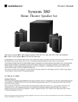
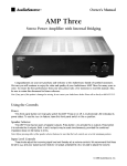
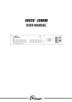
OWNER’S MANUAL
Phoenix Gold International, Inc. 9300 North Decatur Street Portland, Oregon 97203
Tel: 503.286.9300 Fax: 503.978.3381 Tech Support: 800.950.1449
Web: www.phoenixgold.com Email: [email protected]
8100.0303A
WARNING
TO PREVENT FIRE OR SHOCK HAZARD, DO NOT USE THIS PLUG WITH AN EXTENSION CORD, RECEPTACLE
OR OTHER OUTLET UNLESS THE BLADES CAN BE FULLY INSERTED TO PREVENT BLADE EXPOSURE.
TO PREVENT FIRE OR SHOCK HAZARD, DO NOT EXPOSE THIS APPLIANCE TO RAIN OR MOISTURE.
TO PREVENT ELECTRICAL SHOCK, MATCH WIDE BLADE PLUG TO WIDE SLOT, FULLY INSERT.
CAUTION
RISK OF ELECTRIC SHOCK
DO NOT OPEN
This lightning flash with
arrowhead symbol, within an
equilateral triangle, is
intended to alert the user to
the presence of uninsulated
“dangerous voltage” within
the product’s enclosure that
may be of sufficient magnitude to constitute a risk of
electric shock to persons.
Warning: To reduce the risk
of electric shock, do not
remove cover (or back) no
user serviceable parts inside.
refer servicing to qualified
service personnel.
The exclamation point within
the equilateral triangle is
intended to alert the user to
the presence of important
operating and maintenance
(servicing) instructions in the
literature accompanying
the appliance.
IMPORTANT SAFETY INSTRUCTIONS
1.
2.
3.
4.
5.
6.
7.
8.
9.
10.
11.
12.
13.
Read these instructions.
Keep these instructions.
Heed all warnings.
Follow all instructions.
Do not use this apparatus near water.
Clean only with dry cloth.
Do not block any ventilation openings. Install in accordance with the manufacturer’s instructions.
Do not install near heat sources such as radiators, heat registers, stoves, or other apparatus
(including amplifiers) that produce heat.
Do not defeat the safety purpose of the polarized or grounding type plug. A polarized plug has two
blades with one wider than the other. A grounding type plug has two blades and a third grounding
prong. The wide blade or third prong are provided for your safety. If the provided plug does not fit
into your outlet, consult an electrician for replacement of the obsolete outlet.
Protect the power cord from being walked on or pinched particularly at the plugs, convenience
receptacles, and at the point where they exit from the appliance.
Only use attachments or accessories specified by the manufacturer.
Unplug the apparatus during lightning storms or when unused for long periods of time.
Refer all servicing to qualified personnel. Servicing is required when the apparatus has been
damaged in any way, such as power supply cord or plug is damaged, liquid has been spilled or
objects have fallen into the apparatus, the apparatus has been exposed to rain or moisture, does not
operate normally, or has been dropped.
This appliance shall not be exposed to dripping or splashing water and no object filled with liquids such as
vases shall be placed on apparatus.
2
Source Switching Amplifier
Congratulations on your purchase of the AudioSource
AMP200. Please take a few moments to read this entire
manual, and be sure to retain this document for future
reference. Please read and observe all safety instructions
detailed on page two (2).
Using the Controls / Front Panel
Power
The front panel switch will manually switch the AMP200 on or
off. A blue LED behind the faceplate lens indicates its power
status. Whenever the amplifier’s power switch is in the “ON”
position and the amplifier is in “Active” status the lens is
illuminate Blue. If the amplifier is “ON” but in the “Standby”
status the lens is illuminated RED.
Note: If any part of this product is damaged or missing,
please call your dealer or Phoenix Gold Home Products
directly at 800-435-7115 or 503-286-9300.
110V
Fuse Holder
220V
Using the Controls / Back Panel
Power
The AMP200 can be turned on and off independently via a
switch on the front panel, by signal sensing, or remotely by a
triggered DC input. There is a switch located on the lower
edge of the rear panel of the amplifier to select how you
would like to turn on the AMP200. If you would like to control
the unit’s power on / power off status manually from the front,
place the switch in the “Normal” position. If you would like to
control the unit’s power on / power off status by means of
signal sensing, place the switch in the “AUTO ON” position. If
you would like to control the unit’s power on / power off
status by a DC remote trigger, place the switch in the “TRIGGER” position, and connect the remote triggering wire and
ground from your triggering device to the terminal labeled
“TRIGGER IN” next to the switch.
You should use a 3.5mm phone plug in the “IN” connector to
make this connection. The tip of the connector is (+) positive,
and the sleeve of the connector is (-) negative. A second
terminal in the same block is labeled “OUT”. This allows for
remote turn-on of other devices when the AMP300 is powered
on. Use the same polarity for the terminals of this plug. Please
read the owner’s manual for any devices you are attempting to
connect in this manner to ensure compatibility.
Note: The front panel power switch must be in the “ON”
position for the 12V triggers or “Auto ON” features to
operate.
3
Master Level Controls
As an example, if the “Line 1 Input” source was a CD Changer, the
delay could be adjusted to prevent switching back to the “Line 2
Input” source while the changer moves from one disc to another.
Each channel is able to control its volume independently
relative to the other channel. At the bottom left of the rear
panel, there are 2 screwdriver adjustment knobs which
correspond to the volume level of the channel identified by
a channel designator below it.
Speaker Level Input
The AMP200 also provides a pair of speaker level inputs for those
applications where either of the sources has only speaker level
output signal available. This input may be switched to be used in
place of the Line 1 or Line 2 input.
Mode Switch
The volume range is labeled Minimum to Maximum and has
1 steps (clicks) at a center detent position as a reference.
Rotate the knob clockwise to increase output, and counterclockwise to decrease output.
To the right of the Master Level controls is a switch labeled
“MODE” with “STEREO” and “BRIDGED” as options. If you will be
connecting one or two pair of speakers to the amplifier, place
the switch in the “STEREO” position.
These adjustments set the master level and if not set up at
initial setup of the AMP200 will or may adversely affect the
performance of the amplifier.
If you will be using a pair of channels to power a single mono
speaker, place the switch in the “BRIDGED” position, and be
sure to read the section titled “Speaker Terminals” below.
To set the Master Level controls begin by adjusting the front
panel “Volume Trim” to its fully clockwise position. Also set
the front panel “Balance Trim” to its center detent position.
Now adjust both the Left and Right Channel Master Level
controls to set a “Maximum” desired volume for the AMP200
in its application, as well as setting an appropriate “Balance”
from left to right.
When you are using the amplifier in “Bridged Mode”, the amplifier
is now a single channel Mono amplifier. The two channels have
been internally connected in series by the “Bridge” switch. The
AMP200 is now capable of 250W, bridged into 8 ohms with less
than 0.2% THD+N.
Now the front panel Volume and Balance Trim controls can
make fine adjustments to your set up in this application.
For the amplifier to operate properly in the bridged mode you
should have both the “Right and Left” inputs connected to the
amplifier. The amplifier will sum these signals and create your
Mono source.
RCA Input
Line 2
Line 1
S peaker In
R
L
Line 1
+
L
L
_
R
Out
IN
IN
+
NOTE: Both of the “Master Level” adjustments should
be set to the same position, and the “Balance Trim”
should be set to the center or 12 o’clock position for the
amplifier to operate normally in the “Bridged” mode.
Line 2
Delay
Time
_
NOTE: This amplifier will produce in excess of 300 watts
with a bridged pair of channels. Please verify that your
speakers are capable of handling such power to avoid possible
damage!
R
3 Sec
15 Sec
There are a total of 4 RCA inputs on the back panel of the
AMP200. These RCA inputs are labelled as “Line 1 Input” and
“Line 2 Input”. They are also designated with an “R” or an “L”
as Right channel or Left Channel inputs respectively.
Speaker Terminals
Each channel has two pair of multi-way binding post. These are
the red and black screw posts on the rear of the amplifier.
Terminals are provided for “A” and “B” pairs of speakers for each
channel. If you will be using the amplifier as a stereo amplifier
(i.e.- not a bridged amplifier) you will connect the speakers
positive (red) terminal to the amplifiers positive (red) terminal
using the appropriate gauge speaker wire, and the speakers
negative (black) terminal to the amplifiers negative (black)
terminal (immediately below the positive terminal) using the
appropriate gauge speaker wire. If you would like to use one pair
of channels bridged, place the “MODE” switch in the “BRIDGED”
position and use both RED terminals to connect to the speaker.
(See illustration on page 5)
“Line 2 Input” should be used as the “primary’ or normal
input for various line level sources that may be available
locally to the amplifier. “Line 1 Input” is a priority switching
input that can be used for a second input, such as, the
output of a second source, and will take over as the primary
input whenever a signal with a minimum of 5mV of level is
present. Whenever, there is an absence of signal at the “Line
1 Input” RCAs the input will revert back to the normal “Line 2
Input” RCAs input signal. An adjustable delay of from 3
Seconds to 15 Seconds is available and can be set to accommodate the nature of the source connected to the “Line 1
Input” RCAs.
4
This limited warranty applies only to purchases from authorized AudioSource Electronics retailers. This limited warranty is
extended only to the original purchaser and is valid only to
consumers in the United States.
Consumers are required to provide a copy of the original sales
invoice from an authorized AudioSource dealer when making
a claim against this limited warranty. This limited warranty only
covers failures due to defects in materials or workmanship that
occur during normal use. It does not cover failures resulting
from accident, misuse, abuse, neglect, mishandling, misapplication, alteration, faulty installation, modification, service by
anyone other than Phoenix Gold, or damage that is attributable to Acts of God. It does not cover costs of
transportation to Phoenix Gold or damage in transit. The
customer should return their defective product, freight
prepaid and insured, to Phoenix Gold International, Inc.
only after receiving a Return Authorization.
NOTE: Only one pair of channels can be bridged
together. Do not attempt to bridge both A & B
speaker terminals, as this may result in a lower impedance
than the amplifier is designed to accommodate, and may
damage your amplifier. The minimum impedance for the
total load connected to a pair of channels in the bridged
mode is 8-ohm.
This warranty will become void if the serial number identification has been wholly or partially removed, altered or erased.
Repair or replacement under the terms of this warranty does
not extend the terms of this warranty. Should a product prove
to be defective in workmanship or material, the consumer's
sole remedies will be repair or replacement as provided under
the terms of this warranty. Under no circumstances shall
Phoenix Gold be liable for loss or damage, direct, consequential or incidental, arising out of the use of or inability to use the
product. There are no express warranties other than described
above.
NOTE: This amplifier is capable of use with standard
US voltage (115VAC) as well as European voltage
(230VAC). The amplifier will be preset for the voltage of the
country it is sold in. Use with other voltages requires some
changes to be made to the amplifier. Should you wish to use
the amplifier in a country other than the one for which it was
purchased, please contact Phoenix Gold Home Products
support at 1-800-435-7115.
Applications
AMP 200 Specifications
Powering Speakers Outdoors
Power Bandwidth 20Hz-20kHz:
Whenever you are using loudspeakers outdoors, you
should be aware that sound does not travel like it
would in your home. Without the reflective surfaces of walls
and ceilings, sound outdoors will dissipate quickly. Therefore,
in an outdoor situation the AMP200 provides the opportunity
to bridge adjacent channels, effectively doubling the available
power for your speakers. This can help to overcome the
problem of using speakers outdoors assuming the speakers
chosen are capable of handling the additional power.
80W per CH into 8 ohm loads with less than 0.2% THD+N
125W per CH into 4 ohm loads with less than 0.2% THD+N
250W Bridged Mono into 8 ohms with less than 0.2% THD+N
Crosstalk: >65dB @ 1kHz, ref. to rated power into 8 ohms
Frequency Response: (20Hz to 20kHz)+0.0dB, -0.5dB
Signal to Noise ratio: -103dB ref. to rated power into 4 ohms
AC Power Consumption: 700W (all channels driven)
Net Weight: 24.3 lbs (11.0 kgs)
Gross Weight: 32.2 lbs (14.6.0 kgs)
It should be noted that the AMP200 is rated to
operate into a minimum 8-ohm bridged load.
Therefore, if you are using more than a single 8-ohm
loudspeaker in bridged mode you should consider using an
impedance matching speaker selector, such as the Innovative
Home ASM4, ASM6 or ASM8 or possibly using an impedance
matching volume control, such as the Innovative Home VMT1
in a weatherproof housing available at your favorite DIY store
or electrical supply. The choice of a volume control would
allow you the additional flexibility of being able to attenuate
the volume whenever necessary.
AC Mains Fuse:
115V ~ 60Hz T6.3AL, 250V
230V ~ 50Hz T3.15AL, 250V
Limited Warranty
Phoenix Gold International, Inc. (or "AudioSource") warrants its
amplifier products against defects in materials and workmanship for a limited period of time. For a period of two years
from date of original purchase, we will repair or replace the
product, at our option, without charge for parts and labor.
Customer must pay all parts and labor charges after the
limited warranty period expires. The limited warranty period
for factory refurbished products expires after ninety (90) days
from date of original purchase.
5
Stereo Setup
The Audio output of a local source, such as MP3 Player, CD,
television, computer, etc. is connected to the AMP200 via the
Line 1 inputs, and whenever the local source is active its signal
will take priority over the distributed audio signal present at
Line 2 . However, the distributed audio signal will still be
present at the Line 2 input. In this circumstance the audio
output of the local source will be heard via the AMP200. Once
the local source is turned off or muted, the AMP200 will
automatically switch back the distributed audio system as an
audio source, assuming the television is remains inactive. The
delay time adjustment determines when switch back to the
normal source will occur.
In this configuration, the mono switch is set to stereo for
stereo operation. Connect the line out jacks from a stereo
preamplifier or source to the Line 2 input jacks of your
AMP200. Next connect your speakers to the terminals marked
“SPEAKER A” observing proper polarity (see “Speaker Terminals” Page 5). Connect a second (optional) pair of speakers to
the terminals marked “SPEAKER B”. Select between the “A”
and/or “B” speakers using the front panel speaker selection
buttons.
To Source
S peaker In
R
L
Line 1
This set up assumes all incoming signals are at line level and
not at speaker level. If the Whole House Distributed Audio was
only available as a Speaker Level signal you could connect it
the “Speaker In” connections and set the switch above to the
“Line 2” position, or toward the right hand position of the
switch.
Line 2
Line 1
Line 2
Out
IN
IN
+
+
L
L
_
Whole House
Distributed Audio
L
R
Delay
Time
_
R
R
3 Sec
15 Sec
Line 2
Line 1
Mono Setup
S peaker In
R
L
Line 1
In this configuration, the mono switch is set to bridged.
Connect the line out from a preamplifier to the right and left
Line 2 input of your Amp200. Connect your mono speaker to
the terminals of your Amp200, following the instructions in
“Speaker Terminals” on Page 4. Use the “Master Level” controls
on the rear panel to adjust the volume. Leave the balance set
to the center detent position.
Line 2
Out
IN
IN
+
+
L
L
_
Delay
Time
_
R
R
3 Sec
15 Sec
Setup For Multiple Sources
Local Source
Audio Out
In the application shown below, a distributed audio system is
connected to the AMP200 as a local zone amplifier via the Line
2 inputs. Normally the distributed audio system will be the
audio source for the AMP200.
The AMP 200 will no longer be able to pass the Whole House
Distributed Audio to another zone via the Line 2 Output.
The distributed audio is then passed on to be used by
additional zones or sub zones in the distributed system via
the Line 2 outputs.
Whole House
Distributed Audio
Line 2
Line 1
S peaker In
R
L
Line 1
If you have any questions regarding how to set this up, please
call Phoenix Gold Tech support at 800.950.1449.
Line 2
Out
IN
IN
+
+
L
L
_
Delay
Time
_
R
R
3 Sec
Local Source
Audio Out
15 Sec
Whole House
Distributed Audio
6