1
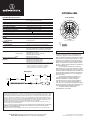
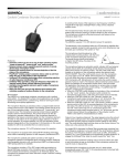
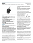
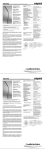
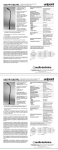
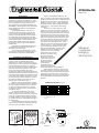
AT933Rx/ML MicroLine Installation and Operation The combination of small size and excellent response makes the AT933Rx /ML ideal for suspension over choirs, instrumental groups or theater stages. A uniform 90° angle of acceptance provides well-balanced pickup over a narrow area. The microphone should be located forward of the front-most source, above the rear-most source, and “aimed” between them (Fig. 1). Increasing the height of the mic above the sources will tend to equalize sound levels between them, but may also increase background/reverberant sound pickup. Whenever possible, the distance from the mic to the rear-most pickup should be no more than twice the distance to the front source, to maintain front-to-rear balance (Fig. 1). Width of pickup is approximately 1.5 times the distance to the closest performer. If additional mics are needed for wide sources, they should not be closer together laterally than 1.5 times the distance to the front source, to avoid phase cancellation (Fig. 2). To orient the microphone in the proper direction, twist the housing slightly in its wire holder (clockwise rotation moves the microphone to the right; counterclockwise rotation moves it to the left). Adjust the vertical angle by changing the number of loops the cable passes through in the steel hanger. The provided foam windscreen simply slips over the MicroLine element, effectively reducing noise from wind or ventilation air currents. Output is low impedance balanced. The output connector of the power module mates with XLRF-type cable connectors. The balanced signal appears across Pins 2 and 3, while the ground (shield) connection is Pin 1. Output is phased so that positive acoustic pressure produces positive voltage at Pin 2, in accordance with industry convention. To shorten the cable, remove the three screws from the base of the power module and slide the outer case up the cable to reveal the circuit board and screw terminals. Loosen the three terminal screws and remove the cable from the module. Next, slide the case off the cable, cut the cable to the desired length (allowing a few extra inches) and slide the case back onto the cable. Tie a single knot in the cable about two inches from the cut end. Following Figure 3, cut the cable off 1" down from the top of the knot and carefully remove 1/2" of the outer jacket. Strip the mic cable wires and attach them to their respective terminals (Fig. 4). Make certain that the terminals are clamped on the conductors, not on the insulation, and that there are no loose strands of wire which might touch other terminals. Replace the case, being certain that it goes over the case grounding contact and that the roll-off switch is accessible. Finish by replacing the three base screws and testing for proper operation. While a modern condenser microphone is not unduly sensitive to the environment, temperature extremes can be harmful. Avoid leaving the microphone in the open sun or in areas where temperatures exceed 110° F (43° C) for long periods of time. Extremely high humidity should also be avoided. Frequency Response (Typical) 10 dB 50 100 200 500 1k 2k 10k 5k Response in dB Description The AT933Rx/ML is a wide-range miniature condenser microphone with a MicroLine polar pattern. It is designed for quality sound reinforcement, professional recording, television, and other demanding sound pickup applications. The AT933Rx/ML is furnished with a vinyl-coated steel hanger adapter that allows it to be adjusted for correct positioning. The microphone features a 50' (15.2 m) permanently-attached miniature cable. Its free end connects to the provided AT8533x power module via internal solderless screw terminals for simple cable-length adjustment in the field. It can be powered from any external 9V to 52V DC phantom power supply. A recessed switch in the power module permits choice of flat response or low-frequency roll-off to help control undesired ambient noise. Four additional interchangeable elements are available to permit selection of angle of acceptance from 90° to 360°. The microphone is enclosed in a rugged housing with a low-reflectance black finish. It is also available in white as the AT933RWx /ML. 20k Frequency in Hertz LEGEND 12" or more on axis (flat) Roll-off Terminal screws LESS THAN DI ST AN CE 2 TIMES “X” Case grounding contact “X Yellow-Yellow Red-Red ” Shield 1" Yellow-Yellow 1 /2 " 90° ANGLE OF ACCEPTANCE 90° 90° MIC A Figure 2 S Y R PC board switch side 1/ 8 " strip reds and yellows MIC B 1.5 TIMES DISTANCE “X” Figure 1 Red-Red Shield strands, fully twisted Figure 3 Figure 4 Miniature Condenser Hanging Microphone AT933Rx /ML Polar Pattern AT933Rx/ML Specifications† Fixed-charge back plate permanently polarized condenser MicroLine 30-20,000 Hz 150 Hz, 6 dB /octave – 36 dB (15.8 mV) re 1V at 1 Pa* 200 ohms (1000 ohms without power module) 131 dB SPL, 1 kHz at 1% T.H.D. Element Polar Pattern Frequency Response Low-frequency Roll-off Open Circuit Sensitivity Impedance Maximum Input Sound Level 105 dB, 1 kHz at Max SPL 68 dB, 1 kHz at 1 Pa* Flat response, low-roll-off (recessed) 9-52V DC, 2 mA typical Dynamic Range (Typical) Signal-to-noise Ratio1 Switch Phantom Power Requirements Weight Microphone Power Module Dimensions Microphone Power Module Output Connector (Power Module) Cable 60 90 270 240 120 150 210 180 SCALE IS 5 DECIBELS PER DIVISION (AT933RWx /ML) 5.61" (142.4 mm) long, 0.31" (8.0 mm) head diameter 3.58" (91.0 mm) long, 0.83" (21.0 mm) diameter Integral 3-pin XLRM-type 50' (15.2 m) long (permanently attached to microphone), 0.13" (3.2 mm) diameter, 2-conductor, shielded cable; free end attaches to screw terminals in power module AT8138 MicroLine foam windscreen; AT8452 MicroLine hanger AT8138WH MicroLine foam windscreen; AT8452WH MicroLine hanger AT8533x power module AT853C-ELE cardioid (120°) AT853H-ELE hypercardioid (100°) AT853O-ELE omnidirectional (360°) AT853SC-ELE subcardioid (170°) † In the interest of standards development, A.T.U.S. offers full details on its test methods to other industry professionals on request. * 1 Pascal = 10 dynes/cm2 = 10 microbars = 94 dB SPL 1 Typical, A-weighted, using Audio Precision System One. 2 These elements require a P12024 element adapter. Dimensions 50 15.2 m 0.31" 8.0 mm 30 300 0.7 oz (20 grams) 2.1 oz (60 grams) Accessories Furnished (AT933Rx /ML) (Both) Optional Interchangeable Elements 2 0 330 3.58" 91.0 mm 0.13" 3.2 mm 5.61" 142.4 mm 0.83" 21.0 mm LEGEND 200 Hz 1 kHz 5 kHz 8 kHz Architects and Engineers Specifications The microphone shall be a fixed-charge condenser with a MicroLine polar pattern and a frequency response of 30 Hz to 20,000 Hz. It shall be capable of accepting optional interchangeable elements for additional polar patterns. It shall operate from an external 9V to 52V DC phantom power source. Nominal open-circuit output voltage with the included power module shall be 15.8 mV at 1 kHz, 1 Pascal. Output shall be low impedance balanced (200 ohms). The microphone shall have a permanentlyattached 50' (15.2 m) miniature cable with a pigtail output. The pigtail output shall connect to a power module via internal solderless screw terminals. The power module shall include a switch for low-frequency roll-off and shall terminate in a 3-pin XLRM-type output connector. The microphone shall be mountable in an included steel hanger that allows permanent overhead installation for pickup of dialogue, orchestras and choirs. The microphone shall be 5.61" (142.4 mm) long with a head diameter of 0.31" (8.0 mm). The microphone weight shall be 0.7 oz (20 grams) without cable. The microphone case, cable and steel hanger shall be black [white]. The Audio-Technica AT933Rx /ML [AT933RWx/ML] is specified. One -Year Limited Warranty Audio -Technica microphones and accessories purchased in the U.S.A. are warranted for one year from date of purchase by Audio-Technica U.S., Inc. (A.T.U.S.) to be free of defects in materials and workmanship. In event of such defect, product will be repaired promptly without charge or, at our option, replaced with a new product of equal or superior value if delivered to A.T.U.S. or an Authorized Service Center, prepaid, together with the sales slip or other proof of purchase date. Prior approval from A.T.U.S. is required for return. This warranty excludes defects due to normal wear, abuse, shipping damage, or failure to use product in accordance with instructions. This warranty is void in the event of unauthorized repair or modification. For return approval and shipping information, contact the Service Department, Audio-Technica U.S., Inc., 1221 Commerce Drive, Stow, Ohio 44224. Except to the extent precluded by applicable state law, A.T.U.S. will have no liability for any consequential, incidental, or special damages; any warranty of merchantability or fitness for particular purpose expires when this warranty expires. This warranty gives you specific legal rights, and you may have other rights which vary from state to state. Outside the U.S.A., please contact your local dealer for warranty details. Audio-Technica U.S., Inc., 1221 Commerce Drive, Stow, Ohio 44224 Audio-Technica Limited, Old Lane, Leeds LS11 8AG England Form No. 0309-9512-01-B/ W P50892-01 1999 Audio -Technica U.S., Inc. Printed in U.S.A.