1
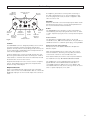
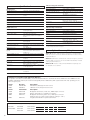
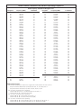
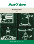
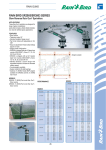
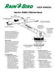
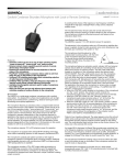
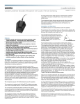
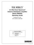
U100 Series
Camera-mount UHF Wireless
Microphone Systems
ATW-U101 Body-pack Transmitter System
ATW-U102 Plug-on Transmitter System
Installation and Operation
U100 Series Camera-mount UHF Wireless Microphone Systems
Installation and Operation
This device complies with part 15 of the FCC Rules. Operation is
subject to the condition that this device does not cause harmful
interference.
This device complies with INDUSTRY CANADA R.S.S. 210, en
conformité avec IC: RSS-210/CNR210. Operation is subject to
the following conditions: 1) This device may not cause harmful
interference and 2) this device must accept any interference
received, including interference which may cause undesired
operation.
Notice to individuals with implanted cardiac pacemakers or
AICD devices:
Any source of RF (radio frequency) energy may interfere with
normal functioning of the implanted device. All wireless
microphones have low-power transmitters (less than 0.05 watts
output) which are unlikely to cause difficulty, especially if they
are at least a few inches away. However, since a “body-pack”
mic transmitter typically is placed against the body, we suggest
attaching it at the belt, rather than in a shirt pocket where it may be
immediately adjacent to the medical device. Note also that any
medical-device disruption will cease when the RF transmitting
source is turned off. Please contact your physician or medicaldevice provider if you have any questions, or experience any
problems with the use of this or any other RF equipment.
CAUTION! The circuits inside the receiver and transmitter have
been precisely adjusted for optimum performance and
compliance with federal regulations. Do not attempt to open the
receiver or transmitter. To do so will void the warranty, and may
cause improper operation.
Warning: To prevent fire or shock hazard, do
not expose this appliance to rain or moisture.
Attention: Pour prévenir feu ou choc
électrique, ne pas exposé l’appareil à la pluie
ou à l’humidité.
Introduction
Thank you for choosing an Audio-Technica professional
wireless system. You have joined thousands of other satisfied
customers who have chosen our products because of their
quality, performance and reliability. This Audio-Technica
wireless system is the successful result of years of design
and manufacturing experience.
The U100 systems are designed primarily for use in audio-forvideo applications, with the receiver mounted on a camera and
connected to the camera’s audio input. U100 systems provide
a choice of 100 PLL-synthesized UHF frequencies. Each
system includes a receiver and either a body-pack or plug-on
transmitter:
System
Receiver
Transmitter
ATW-U101
ATW-U102
ATW-R100
ATW-R100
ATW-T101 Body-pack
ATW-T102 Plug-on
The ATW-R100 receiver features true diversity reception. Two
antennas feed two completely independent RF sections on
the same frequency; automatic logic circuitry continuously
compares and selects the superior received signal, providing
better sound quality and reducing the possibility of dropouts.
Front-end helical filter design improves rejection of
interference. The receiver also offers balanced audio output
with level control, a headphone jack with volume control,
removable antennas, a hinged battery door, and LED
indicators. It operates on two internal 9V batteries or external
12V DC.
Each transmitter is powered by one internal 9V battery and
has an Off/Standby/On switch, input level control, battery
condition indicator and channel selector switches. The
ATW-T101 body-pack transmitter has an industry-standard
TB5M input connector with both low- and high-impedance
inputs plus a bias connection. The ATW-T102 has a 3-pin
XLRF-type input connector with a locking collar.
Please note that in multiple system applications there must
be a transmitter-receiver combination set to a separate
frequency for each input desired (only one transmitter for each
receiver). Because the operating frequencies of U100 Systems
are in UHF TV frequencies, only certain wireless frequencies
may be useable in a particular geographic area. Also, only
certain of the available operating frequencies may be used
together. Suggestions for multiple-system frequency grouping
will be found on page 7.
2
Receiver Setup
Channel Selector
Switches
Monitor
Headphone
Output Jack
ANT.A
MONITOR
X10
9 0 1
28
37
6 5 4
ANT.B
PEAK
X1
9 0 1
8
7
AF Peak
Indicator
Antennas
Attach the antennas to the antenna input jacks. Make certain
that during operation there is a clear open-air path between
the receiver antennas and the transmitter.
2
3
6 5 4
PWR
A
MONITOR
LEVEL
INT OFF EXT
A headphone jack and level control permit monitoring of
the audio signal. Either mono or stereo headphones with
a 3.5 mm plug may be used; the audio is supplied to both
sides of a stereo unit.
OUT
LEVEL
Monitor
Output
Tuner “A”
Headphone
Level
Antenna
Level Control
Control
Jack
Tuner “A”
Operation
Power
Indicator
Switch/Indicator
B
Tuner “B”
Antenna
Jack
Tuner “B”
Operation
Indicator
Fig. A
Location
The ATW-R100 receiver is designed primarily to be mounted
to professional video cameras (mounting methods and
positions will vary with the camera being used). However, the
receiver will provide outstanding professional performance in
other wireless applications as well.
For best operation the receiver should be at least three feet
above the ground and at least three feet away from a wall or
metal surface to minimize reflections. The transmitter should
be at least three feet from the receiver.
Keep antennas away from noise sources such as computers,
motors, automobiles and neon lights; also keep antennas
away from large metal objects.
Output Connections
There is one balanced audio output (31.6 mV) on the back
panel of the receiver. Use shielded audio cable to connect this
XLRM-type 3-pin jack to the mic audio input of the camera or
mixer.
Power
The ATW-R100 receiver operates on either external DC or
internal battery power by setting the Power switch to “EXT”
or “INT” respectively (Fig. A). In the center position all power
is off.
External Power
The back panel is equipped with a jack for an external
12-18V DC source, 200 mA nominal current. The jack takes a
standard 2.5 mm I.D. coaxial DC power plug, center positive.
Battery Selection and Installation
Always use two fresh alkaline 9V batteries. Replace the
batteries in pairs.
Open the hinged battery door on the side of the receiver.
Insert two batteries, observing correct polarity as marked
on the inside of the door. Close and latch the door.
Note that the battery door will not close fully if the batteries
are installed incorrectly. Do not force the door closed.
The U100 Series receiver and transmitters accept most
popular brands of 9-volt alkaline batteries. But there is
considerable variation in battery sizes; some alkaline and
extended-life batteries may not fit correctly, which can cause
units to operate improperly or not at all.
3
Transmitter Setup
Input
Connector
Power Switch
(Off/Standby/On)
Antenna
INPUT
ST.BY
ATW-T101
BATT
ON
OFF
Fig. B
Battery Condition
Indicator
Transmitter Input Connections
Connect a microphone to the audio input connector on the
transmitter.
ATW-T101
The ATW-T101 body-pack transmitter has an industry-standard
TB5M input connector with both low- and high-impedance
inputs plus a bias connection.
ATW-T101 Input Connections
5
4
1
Battery
Compartment
Input
Level Control
(shown set to
“Hi”)
Channel Selector
Switches
MIC
LVL
CHANNEL
3 56
3 56
3
7 3
7
8 2
8
2
109
109
Fig. C
Input
Connector
X10
X1
Lo Hi
Power Switch
(Off/Standby/On)
Battery Condition
Indicator
BATT
OFF
STAND BY
ON
ATW-T102
9 0 1
Hi
MIC LEVEL
6 5 4
X10
2
3
8
7
6 5 4
X1
CHANNEL
Fig. D
Microphone
Level Control
3
2
Pin
Transmitter
Connections
Condenser Mic
Input Connections
Dynamic Mic
Hi-Z Line
1
Shield (Ground)
Shield/Bias –
Shield/Audio “–“
Shield/Audio “–“
2
Bias + Out
Bias + In
Open
Open
3
Lo-Z Mic In
Mic Audio
Mic Audio “+”
Jumper to Pin 1
4
Source Load
(2.2 kV)
Jumper to
Pin 1
Open
Jumper to
Pin 1
5
Hi-Z Line In
Open
Open
Line Audio ”+”
ATW-T102
The ATW-T102 plug-on transmitter has a 3-pin XLRF-type
input connector with a locking collar. To attach the
microphone, rotate the threaded locking collar fully clockwise
(“down”) until it reaches the transmitter housing (Fig. E1).
Then rotate the collar back “up” one or two turns to expose
the microphone latch.
9 0 1
2
3
8
7
Lo
Channel Selector
Switches
Battery Selection and Installation
Always use a fresh alkaline 9V battery.
Press the microphone and transmitter together (Fig. E2),
making certain that the latch “clicks” into the base of the mic.
Pull on the mic to make certain it is latched on the connector.
Continue to rotate the threaded collar “up” until it is firmly
against the end of the mic (Fig. E3). Make certain the mic is
securely attached before use.
To detach the microphone, reverse the steps above. Always
loosen the threaded collar fully before attempting to
disconnect the mic.
Open the hinged battery door. Insert the battery, observing
correct polarity as marked inside the battery compartment.
Close the battery door. Do not force the door closed.
Battery Condition Indicator
After the battery is installed, turn the power on. The battery
condition indicator LED (Fig. B/D) should flash momentarily.
If it does not, the battery is installed incorrectly or it is dead.
If the indicator LED stays on (does not flash), the battery
voltage is low and the battery should be replaced. If this
happens during use, replace the battery immediately to
ensure continued operation.
“CLICK”
E1
Latch
E2
Fig. E
E3
4
TB5M Connector,
Top View
ATW-T102 Input Connections
Pin 1
Case Ground
Pin 2
Audio “+” and 5V DC bias
Pin 3
Audio “–” and 5V DC bias
Use a dynamic microphone, or a condenser mic with an
internal battery. In addition, the ATW-T102 provides a bias
voltage of +5V on Pins 2 and 3 which will power some
“battery/phantom” mics designed to work at this low voltage.
However, the ATW-T102 will not power a “phantom
powered” mic which requires the more-typical 12 to 48 volts.
Use of the bias voltage will reduce battery life slightly.
Presence of the bias voltage will not affect dynamic
microphones.
Transmitting Antenna
The ATW-T101 body-pack transmitter includes a permanentlyattached flexible antenna. For best results, allow the antenna
to hang freely and full length from the bottom of the
transmitter. If the received signal is marginal, experiment
with different transmitter positions on your body; or try
repositioning the receiver. Do not attempt to remove, replace
or change the length of the transmitting antenna. (The
stainless-steel mounting clip may be oriented in one of four
“directions.” Loosen its mounting screw, reposition the clip
in the case recess as desired and re-tighten the screw.)
The ATW-T102 plug-on transmitter’s antenna is housed in a
non-metallic section between the metal transmitter case and
the mic connector. For best operation, hold the body of the
microphone itself and do not cover or obstruct the antenna
area.
System Operation
Setting Channels
Use the provided screwdriver to set the channel selector
switches on the receiver and transmitter to the same
frequency (Fig. A/C/D).
As an example, setting the X10 selector on “5” and the X1
selector on “2” designates channel 52, operating at 734.625
MHz as shown on the chart on page 7.
Be certain the units are turned off when making
frequency changes.
Receiver On . . .
Turn down the output level of the receiver (OUT LEVEL) and
the input level control of the camera or mixer.
Turn the receiver on, choosing either “INT” (internal battery)
or “EXT” (external DC source) as appropriate. The power
indicator LED (PWR) will light up strongly with fresh batteries.
(If the LED becomes dim or extinguished, the batteries are
weak and should be replaced immediately for reliable
operation.)
If the tuner operation indicator LEDs (A and B) flicker, there
may be RF interference. If this occurs, select another
frequency. (Always turn the receiver off when making
frequency changes.)
Transmitter On . . .
Before turning on the transmitter, be certain the transmitter
channel selector switches are set to the same numbers as
those on the receiver.
(–36 dBV) at 1 Pascal/94 dB SPL, while providing excellent
signal-to-noise ratios and maximum-acoustic-input levels.
1. Set the transmitter Mic Level control to the full
counter-clockwise (Lo) position.
2. Make an initial adjustment of the receiver output and
camera/mixer input level controls that will allow audio
through the system as you increase the transmitter Mic
Level.
3. Plug in the mic and power up the system.
4. While speaking/singing into the microphone at typically-loud
levels, increase the transmitter Mic Level adjustment until
the maximum audio output of the mic lights the receiver’s
Peak indicator. (Do not set the transmitter level too high –
doing so will cause the system to overload and distort.)
5. Now, while speaking/singing into the microphone at
typically-loud levels, adjust the output level of the receiver
so the highest sound pressure level going into the
microphone causes no input overload in the camera/mixer,
and yet permits the camera/mixer level controls to operate
in their “normal” range (not set too high or too low). This
provides the optimum signal-to-noise for the entire system.
Setting Line Level (ATW-T101)
When using a line-level source with the ATW-T101
transmitter, set the input level using the same method given
above. The Mic Level (MIC LVL) control adjusts audio gain for
both mic and line inputs.
The transmitter has a three-position power switch. When
the switch is set to “Standby,” (“ST.BY”) the transmitter
produces RF with no audio signal. When the switch is “On,”
the transmitter produces both RF and audio. With the
switch “Off,” there is minimum noise output from the
receiver due to a special A-T muting system.
RF Interference
Please note that wireless frequencies are shared with other
radio services. According to Federal Communications
Commission regulations, “Wireless microphone operations
are unprotected from interference from other licensed
operations in the band. If any interference is received by any
Government or non-Government operation, the wireless
microphone must cease operation . . .”
Setting Mic Levels
CAUTION! Adjust the Mic Level control carefully. Unlike the
Channel Selector switches, it will not rotate continuously!
If you need assistance with operation or frequency selection,
please contact your dealer or the Audio-Technica professional
division.
The microphone input accommodates a wide range of mics
with typical sensitivity ratings of 1.5 mV (–56 dBV) to 15 mV
Extensive wireless information also is available on the
Audio-Technica Web site at www.audio-technica.com.
Turn the transmitter on.
5
Specifications †
Overall System
Operating Frequency
Number of Channels
Frequency Stability
Modulation Mode
Normal Deviation
Operating Range
Operating Temperature Range
Frequency Response
ATW-R100 Receiver
Receiving System
Image Rejection
Signal-to-Noise Ratio
Total Harmonic Distortion
Sensitivity
Intermediate Frequency
Audio Output (balanced)
Output Connector
Monitor Headphone Output
(typical)
Monitor Headphone Jack
External Power Requirements
Batteries
Current Consumption
Battery Life
Dimensions
Net Weight (without batteries)
Accessories Included
UHF band, 728.125-740.500 MHz
100 total
±0.005%, Phase Lock Loop frequency
control
FM
±10 kHz
300' typical (ATW-U102: 200' typical)
41° F (5° C) to 113° F (45° C)
100 Hz to 15 kHz
Dual independent receivers, automatic
switching diversity
35 dB nominal
107 dB at 30 kHz deviation
(IEC-weighted), maximum modulation
75 kHz
<1% (10 kHz deviation at 1 kHz)
26 dBmV, (S/N 60 dB at 5 kHz deviation,
IEC-weighted)
45 MHz, 10.7 MHz
31.6 mV (at 1 kHz, ±5 kHz deviation, 10k
ohm load)
3-pin XLRM-type
75 mW max. at 1 kHz, 1% T.H.D.,
into 32 ohm (each channel) stereo
headphones
3.5 mm TRS, signal on both Tip and Ring
12V DC nominal, 200 mA
Two 9V (NEDA type 1604) alkaline, not
included
130 mA typical
Approximately 5-7 hours (depending on
battery type and use pattern)
3.35" (85.0 mm) W x 4.53" ( 115.0 mm) H
x 1.42" (36.0 mm) D
12.0 oz (340 grams)
Two flexible UHF antennas; control
screwdriver
ATW-T101 Body-pack Transmitter
RF Power Output
50 mW Max
Spurious Emissions
Under federal regulations
Input Connector
TB5M
Line Input Impedance/Level
100k ohms/3.16V max. input at 1 kHz,
1% T.H.D.
Battery
9V (NEDA type 1604) alkaline,
not included
Current Consumption
50 mA typical
Battery Life
Approximately 8-10 hours (depending on
battery type and use pattern)
Dimensions
2.52" (64.0 mm) W x 3.78" (96.0 mm) H
x 0.91" (23.0 mm) D
Net Weight (without battery)
5.0 oz (143 grams)
ATW-T102 Plug-on Transmitter
RF Power Output
Spurious Emissions
Input Connector
Battery
Current Consumption
Battery Life
Dimensions
Net Weight (without battery)
50 mW Max
Under federal regulations
3-pin XLRF-type
9V (NEDA type 1604) alkaline,
not included
60 mA typical
Approximately 7-9 hours (depending on
battery type and use pattern)
1.58" (40.0 mm) W x 4.32" (109.8 mm) H
x 1.58" (40.0 mm) D
6.2 oz (177 grams)
† In the interest of standards development, A.T.U.S. offers full details on its test methods
to other industry professionals on request.
Optional Accessory Microphones
AT831cT5 Miniature cardioid condenser microphone, terminated with a
TA5F connector for use with the ATW-T101 transmitter. Includes clothing
clip and windscreen.
MT830cT5 Subminiature omnidirectional condenser microphone, terminated with a TA5F connector for use with the ATW-T101 transmitter. Includes
clothing clip and windscreens.
MT830cT5-TH “Theater” model, same at MT830cT5 except beige color
mic and cable for concealment.
U100 Series Compatible with 7000 Series Wireless
For greater convenience and flexibility, receivers and transmitters in the Audio-Technica U100 Series and 7000 Series are
available individually and may be used interchangeably. All are 100-channel, PLL-synthesized UHF units operating on the
same frequency-set.
Series
U100
7000
Receiver
ATW-R100
ATW-R73
Description
Miniaturized, battery-powered receiver
Half-rack-mount, AC-powered receiver
Series
U100
U100
7000
Transmitter
ATW-T101
ATW-T102
ATW-T75
7000
ATW-T76
Description
Body-pack transmitter, metal case, TB5M input connector
Plug-on transmitter for separate microphone
Body-pack transmitter, plastic case, HRS input connector
(Requires A-T mics with model numbers ending in “cW.”)
Integrated handheld microphone/transmitter
For future reference, please record your system information here.
6
Receiver
ATW-R100
Serial Number
Transmitter
ATW-T101
Serial Number
ATW-T102
Serial Number
Audio-Technica U100 Series UHF Wireless Operating Frequencies
U100 Frequency and Channel Designator List
Designator
Frequency (MHz)
TV Channel
Designator
Frequency (MHz)
TV Channel
00
01
02
03
04
05
06
07
08
09
10
11
12
13
14
15
16
17
18
19
20
21
22
23
24
25
26
27
28
29
30
31
32
33
34
35
36
37
38
39
40
41
42
43
44
45
46
728.125
728.250
728.375
728.500
728.625
728.750
728.875
729.000
729.125
729.250
729.375
729.500
729.625
729.750
729.875
730.000
730.125
730.250
730.375
730.500
730.625
730.750
730.875
731.000
731.125
731.250
731.375
731.500
731.625
731.750
731.875
732.000
732.125
732.250
732.375
732.500
732.625
732.750
732.875
733.000
733.125
733.250
733.375
733.500
733.625
733.750
733.875
57
57
57
57
57
57
57
57
57
57
57
57
57
57
57
57
57
57
57
57
57
57
57
57
57
57
57
57
57
57
57
57
57
57
57
57
57
57
57
57
57
57
57
57
57
57
57
50
51
52
53
54
55
56
57
58
59
60
61
62
63
64
65
66
67
68
69
70
71
72
73
74
75
76
77
78
79
80
81
82
83
84
85
86
87
88
89
90
91
92
93
94
734.375
734.500
734.625
734.750
734.875
735.000
735.125
735.250
735.375
735.500
735.625
735.750
735.875
736.000
736.125
736.250
736.375
736.500
736.625
736.750
736.875
737.000
737.125
737.250
737.375
737.500
737.625
737.750
737.875
738.000
738.125
738.250
738.375
738.500
738.625
738.750
738.875
739.000
739.125
739.250
739.375
739.500
739.625
739.750
739.875
58
58
58
58
58
58
58
58
58
58
58
58
58
58
58
58
58
58
58
58
58
58
58
58
58
58
58
58
58
58
58
58
58
58
58
58
58
58
58
58
58
58
58
58
58
47
48
49
734.000
734.125
734.250
58
58
58
95
96
97
98
99
740.000
740.125
740.250
740.375
740.500
59
59
59
59
59
Multi-channel Systems
Following are groupings of frequencies suggested for multi-channel wireless systems.
Group A: Channels 00, 02, 08, 15, 46, 50, 60 (or 62), 71, 76, 80, 93, 99 - or Group B: Channels 01, 03, 07, 25, 30, 41, 44, 56, 69, 76, 77, 86
For use where TV Channel 57 is operating:
Channels 50, 60 (or 62), 71, 76, 80, 93, 99 (from Group A) - or Channels 56, 69, 76, 77, 86 (from Group B)
For use where TV Channel 58 is operating:
Channels 00, 02, 08, 15, 46, 99 (from Group A) - or Channels 01, 03, 07, 25, 30, 41, 44 (from Group B)
For use where TV Channel 59 is operating:
Channels 00, 02, 08, 15, 46, 50, 60 (or 62), 71, 76, 80, 93 (from Group A) - or Channels 01, 03, 07, 25, 30, 41, 44, 56, 69, 76, 77, 86 (All of Group B)
7
Ten Tips To Obtain The Best Results
1. Use only fresh alkaline batteries; replace the receiver
batteries in pairs. Do not use “general purpose” (carbonzinc) batteries.
2. Position the receiver so that it has the fewest possible
obstructions between it and the normal location of the
transmitter. Line-of-sight is best.
3. The transmitter and the receiver should be as close
together as conveniently possible, but no closer together
than three feet.
4. The receiver antennas should be in the open and away
from any metal.
5. The transmitter and receiver must be set to the same
channel number.
6. Only one transmitter on a given frequency should be
“on” at a time.
7. The power switch on the transmitter has three
positions: “Off,” “Standby,” and “On.” In the middle
“Standby” position, the transmitter sends only RF to
the receiver; the audio source is turned off.
8. If the “Out Level” of the receiver is set too high, it
may over-drive the input of the camera/mixer or clip
the output of the receiver, causing distortion.
Conversely, if the receiver output is set too low, the
overall signal-to-noise ratio of the system may be
reduced.
9. You need to change channels 1) when a strong
interference signal is received, 2) when the channel
breaks down, or 3) during multiple-system operation in
order to select an interference-free channel. Always
turn the units off before changing frequencies.
10. Turn the receiver and transmitter off when not in use.
Remove the batteries during long-term storage.
One-Year Limited Warranty
Audio-Technica professional wireless systems purchased in the U.S.A. are warranted for one year from date of purchase by Audio-Technica U.S., Inc.
( A.T.U.S.) to be free of defects in materials and workmanship. In event of such defect, product will be repaired promptly without charge or, at our
option, replaced with a new product of equal or superior value if delivered to A.T.U.S. or an Authorized Service Center, prepaid, together with the
sales slip or other proof of purchase date. Prior approval from A.T.U.S. is required for return. This warranty excludes defects due to normal wear,
abuse, shipping damage, or failure to use product in accordance with the instructions. This warranty is void in the event of unauthorized repair or
modification, or removal or defacing of the product labeling.
For return approval and shipping information, contact the Service Dept., Audio-Technica U.S., Inc., 1221 Commerce Drive, Stow, Ohio 44224.
Except to the extent precluded by applicable state law, A.T.U.S. will have no liability for any consequential, incidental, or special damages; any
warranty of merchantability or fitness for particular purpose expires when this warranty expires.
This warranty gives you specific legal rights, and you may have other rights which vary from state to state.
Outside the U.S.A., please contact your local dealer for warranty details.
Audio-Technica U.S., Inc., 1221 Commerce Drive, Stow, Ohio 44224
P51176-B/W
©1999 Audio-Technica U.S., Inc.
330/686-2600
Printed in Japan
www.audio-technica.com