1
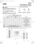
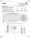
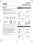
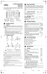
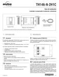
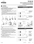
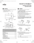
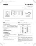
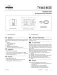
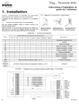
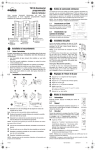
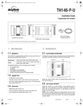
400-144-003-C (TH144_HP) ENG.fm Page 1 Friday, February 8, 2008 10:29 AM
TH144
Installation and User Guide
Electronic Thermostat for a Heat Pump
n
Installation
1.
1.2
Prepare and Connect the Thermostat
TURN OFF POWER TO THE SYSTEM AT THE MAIN POWER
PANEL TO AVOID ELECTRICAL SHOCK.
Installation should be carried out by an electrician or a qualified
technician.
1.1
Find a Location for the Thermostat
• For a new installation, choose a location about 5 ft. (1.5 m) above
the floor and on an inside wall.
• Avoid locations where there are air drafts (top of staircase, air outlet), dead air spots (behind a door), direct sunlight, concealed
chimneys or pipes, or air diffusers.
Loosen the captive screw
holding the base to the
module.
Gently lift the lower part of
the module to remove it
from the base.
Secure the base using the
wall anchors & screws.
Wire the thermostat.
TABLE 1: Wiring Terminals
OUTPUT CONFIGURATION (MODEL)
Terminals
1H1C
Geothermal
R
D
D
C
W
Y
D
2H1C
D
D
D
D
Y1
Y2
G
O/B
Fault
REM
Vcc (1)
Tx/Rx (2)
Gnd (3)
a.
D
D
D
D
D
D
2H2C
Geothermal
D
D
Connect to...
3H2C
D
D
D
Supply 24 VAC
Common
Auxiliary heat relay
Compressor relay
D
D
D
D
D
D
D
D
D
D
First compressor relay
Second compressor relay
Fan relay
Reversing valve
Heat pump fault output
Unoccupied input (optional) - see 1.3
CT240/CT241/timer
AC144-02 Remote Indoor and Outdoor
Temperature Interface - see 1.4
AC144-02a
For 2H1C & 3H2C models, the AC144-02 is required to use the balance point option (compressor cut-off).
FIGURE 1: Typical Wiring Diagram (model shown TH144-3H2C)
TH144
400-144-003-C
2008-02-08
1/6
400-144-003-C (TH144_HP) ENG.fm Page 2 Friday, February 8, 2008 10:29 AM
1.3
Connecting the REM input (optional)
1.5
To remotely activate the Unoccupied mode, the REM input allows
connection to an optional CT240/CT241 telephone controller, a
central timer or an alarm system.
A closed contact remotely activates the Unoccupied mode (see 4.1).
First Power On
When you power TH144 for the first time, it
runs a sequence of tests and resets itself,
which lasts approximately 10 seconds. The
default setpoint is 20°C (68°F).
NOTE: The displayed ambient temperature
24 VAC
24 VAC
might be higher than the real ambient temperature if you are holding the thermostat.
Non-programmable models
Programmable
models
For the programmable models, open the thermostat’s door, and set
the time (Hour and Minute) and day (Day).
NOTE: To protect the compressor, TH144 has an On/Off delay of 2
or 4 minutes (default is 2 minutes) before starting or stopping the
system (see the following section).
1.4
24 VAC
1.6
TIMER
The TH144 offers many configuration options
using the DIP switches located on the back of
the thermostat. Default settings are inside the
shaded cells.
Connecting the AC144-02 RTI (optional)
The AC144-02 Remote Temperature Interface (RTI) connects to a
TH144 thermostat for remote indoor or outdoor temperature
readings.
NOTE: If you wish to use the balance point cut-off function to cut the
heat pump compressor when the outdoor temperature drops below
the defined cut-off setpoint (see section 4.4 to define this setpoint),
you must connect a remote temperature interface.
NOTE: Refer to the AC144-02 installation instructions for details on
Configure the TH144
NOTE: After first power-up, wait at least 5 min-
utes while the internal battery is being charged
before configuring TH144.
Name
DESCRIPTION
UP
DOWN
°C/24h
°F/12h
Select the display format. When you
Display change the display format, the set-
how to connect the RTI to the thermostat.
points revert to their default values.
20 minutes = heavy commercial
applications
15 minutes = residential & light
commercial applications
Cycle
1.4.1 Remote Indoor Sensing
The REM icon indicates that the
temperature is controlled from a remote
location using the RTI’s housing sensor or
the connected probe(s).
Temperature averaging can be obtained
using up to 4 probes.
To return to local control, disconnect the
RTI wires at the thermostat terminals and
turn off for at least 5 seconds.
1.4.2 Remote Outdoor Sensing
The OUT icon indicates the outdoor
temperature read from the outdoor probe
connected to the RTI.
On some models (2H1C & 3H2C), the
outdoor temperature is used for the compressor cut-off point.
TH144
NOTE: On models not equipped with 20 min. 15 min.
the Protect switch, the On/Off delay is
set based on the cycle. That is, the
On/Off delay is 4 minutes for the 20
minute-cycle and is 2 minutes for the
15 minute-cycle.
Aux
W = the compressor turns Off during
auxiliary heating.
W + Y = the compressor remains On
during auxiliary heating.
Keys
Lock the keypad. The
icon is displayed when any button is pressed to
indicate that the setpoint or operating
mode cannot be modified. On the programmable models, the schedule cannot be modified as well.
W
W+Y
Lock
Unlock
4 min.
2 min.
1H1C
2H2C
B
O
To protect the compressor against too
Protect frequent On/Off, TH144 provides an
On/Off delay selectable via this switch.
Stages Select between 2H2C and 1H1C.
Valve
Select the polarity of the reversing
valve. B= the valve is energized during
heating. O= the valve is energized during cooling.
400-144-003-C
2008-02-08
2/6
400-144-003-C (TH144_HP) ENG.fm Page 3 Friday, February 8, 2008 10:29 AM
o
I
Basic Configuration
Comfort
setpoint
Economy
setpoint
2.
Unoccupied
setpoint
Schedule
programming
Select
operating
mode
Heat Pump Fault
(red)
PROGRAMMABLE
NON PROGRAMMABLE
Select fan
mode
HEAT
Controls the heating unit(s).
COOL
Controls the cooling unit(s).
OFF
Both units (HEAT and COOL) are OFF. The fan function
is still enabled but no setpoint changes are allowed.
AUTO
Automatic changeover. Automatically alternates
between HEAT and COOL. See section 4.5 for details.
2.2
To adjust the temperature or to
view a setpoint (press once)
Symbol
Current day (see 1.5)
Room temperature OR
setpoint (arrow)
REM = temperature is
controlled using AC144-02
(see 1.4)
See table below
OUT = outside temperature
from the connected
AC144-02 (see 1.4)
Current control
mode (see 2.1)
Predefined Setpoints
Predefined setpoints represent the temperature that you wish to have
during the day, at night or while you are away. The Comfort and
Economy setpoints are used with the Automatic mode (schedule, for
programmable models) while the Unoccupied setpoint can be used
with the Unoccupied mode (activated manually or remotely). This
table displays the default setpoints:
Select
control
mode
Current time
(see 1.5)
Select the Control Mode
The mode indicates which system is used for temperature control.
Use the Heat / Cool button to select one of the following modes:
Yellow indicator
1H1C/2H2C
(Unoccupied)
2H1C/3H2C
(Emergency Heat
control mode is
selected and the
Aux. heat is on)
Time and
day settings
2.1
Predefined
Setpoint
HEAT
COOL
Comfort
21°C (70°F)
25°C (78°F)
Economy
17°C (62°F)
28°C (82°F)
Unoccupied
10°C (50°F)
35°C (95°F)
2.2.1 To Modify the Predefined Setpoints
NOTE: If your thermostat controls both HEATING and COOLING, the
predefined setpoints must be configured for both applications.
NOTE: The Cool setpoints cannot be lower than the Comfort Heat
setpoint. If this should happen, the TH144 will automatically set your
Cool setpoint 1°C (1°F) higher than your Comfort Heat setpoint.
This icon is always displayed with the
represent the programs setpoints.
or
COOL
HEAT
Programmable models only. Automatic Operating mode is
executing your schedule.
icon which
Programmable models only. Manual Operating mode. This
icon is either displayed alone (a manual setpoint was set) or
with the
or
icon
Comfort setpoint. Associated with programs 1 and 3.
Can also be used with manual mode or during a bypass.
Economy setpoint. Associated with programs 2 and 4.
Can also be used with manual mode or during a bypass.
Unoccupied setpoint. Activated from the TH144 or remotely
(REM input is connected to a remote system)
The fan runs continuously.
The heating system is ON.
2.3
View the Current Setpoint
To view the current setpoint, briefly press one
of these buttons
once. The arrow
indicates the setpoint.
The air conditioning system is ON.
TH144
400-144-003-C
2008-02-08
3/6
400-144-003-C (TH144_HP) ENG.fm Page 4 Friday, February 8, 2008 10:29 AM
p
3.1
Programming
3.
To program this schedule
n
Program Your Schedule
The TH144 allows four setting changes for each day of the week.
There are no pre-set programs.
For each day, enter the time at which you wake up (P1), the time you
leave for work (P2), the time you return home (P3) and the time you
go to bed (P4):
o
p
q
Programs
Associated Setpoint
Time
r
P1
(Comfort)
Wake up
P2
(Economy)
Leave home
P3
(Comfort)
Return home
P4
(Economy)
Night
NOTE: For temperature increases (P1 and P3), allow at least 15
minutes per 1°C (2°F). For example, if you have lowered the temperature by 3°C (6°F) during the night and you wake up at 7 a.m., program the change for 6:15 a.m.
To reduce energy costs, you must lower the temperature for a period
of 2 to 3 times the delay required to bring the temperature back to
your comfort level.
3.1.1 Set or Modify the Programs
• After 60 seconds of inactivity, the thermostat will automatically exit
programming mode.
s
t
Press Program. MO and P1 are
displayed.
Press and hold Day for 3 seconds to
select all days of the week
(MOTUWETHFRSASU).
Set the time (6:00) using Hour and
Minute.
Press Program to select P2. Set the
time (8:30) using Hour and Minute.
Press Program to select P3. Set the
time (4:00 p.m.) using Hour and
Minute.
Press Program to select P4.
Set the time (11:00 p.m.) using Hour and
Minute.
Press Mode/Return to exit
To erase programs 2 and 3 for
Saturday and Sunday
n
o
p
q
r
s
Press Program to access programming mode.
Press Program until P2 is selected.
Press Day to select Saturday (SA) and press Clear.
Press Day to select Sunday (SU) and press Clear.
Repeat steps 2 to 4 for P3.
Press Mode/Return to exit.
• It is sometimes faster to program the same schedule for the entire
week and then modify the exception days.
3.2
n
o
Press Program. MO and P1 are displayed.
The TH144 offers 2 operating modes:
If necessary, press Day to select the day to be programmed or
hold Day for 3 seconds to select all days of the week.
Press Hour and Minute to set the start time.
3.2.1 Automatic
p
(- - : - -) when the program is inactive.
NOTE: This mode can be bypassed for up to
Press Program to select the next program.
two hours (see 4.2).
Repeat steps 2 to 4 for remaining programs.
3.2.2 Manual
Press Mode/Return to exit.
Maintains a constant temperature. To activate:
3.1.2 Programming Example
Comfort (programs 1 and 3):
• starts at 6:00 a.m. and 4:00 p.m. from Monday to Friday
• starts at 6:00 a.m. on Saturday and Sunday
Economy (programs 2 and 4):
• starts at 8:30 a.m. and 11:00 p.m. from Monday to Friday
• starts at 11:00 p.m. on Saturday and Sunday
PROG
1
2
3
4
TH144
MON
TUE
WED
THU
FRI
SAT
SUN
6:00
6:00
6:00
6:00
6:00
6:00
6:00
--:--
--:--
8:30
PM
PM
4:00
11:00
8:30
PM
PM
4:00
11:00
8:30
PM
PM
4:00
11:00
This mode executes the programmed schedule.
To activate:
is displayed. The
Press Mode/Return until
associated program setpoint icon is also displayed.
NOTE: To clear an entry, press Clear; the time zone indicates
q
r
s
Select the Operating Mode
8:30
PM
PM
4:00
11:00
8:30
PM
PM
4:00
11:00
--:-PM
11:00
n
o
Press Mode/Return until
is displayed.
Set temperature
OR quickly press
or
to use a pre-defined setpoint.
Temperature setpoint
using arrow buttons.
Fixed setpoint automatic changeover *
or
Temperature setpoint
using a predefined setpoint button.
Heat and Cool setpoints
are used for automatic
changeover *
--:-PM
11:00
* if you are using the automatic changeover mode, see 2.1 and 4.5.
400-144-003-C
2008-02-08
4/6
400-144-003-C (TH144_HP) ENG.fm Page 5 Friday, February 8, 2008 10:29 AM
q
4.1
Other Information
4.
Remote Unoccupied
• The yellow LED on top of the display turns on
when the unoccupied mode is activated
(1H1C/2H2C models only).
4.5.1 Fixed Setpoint (
icon is displayed.
• For details on how to operate your telephone
controller (CT240/CT241), refer to its
manual.
• When this mode is activated remotely it can
only be deactivated remotely. Although, it can be bypassed for a
2-hour period (see 4.2).
4.2
When the TH144 is in Automatic or Remote Unoccupied mode, you
can temporarily bypass the current setpoint for a 2-hour period after
which it will return to the previous mode.
Automatic (schedule programs)
or quickly press
)
When you set the temperature using the
arrow buttons, the
TH144 uses this unique temperature setpoint for temperature control.
The thermostat automatically switches to HEAT mode when the
ambient temperature drops under the temperature setpoint whereas
the COOL mode is activated when the temperature rises above the
temperature setpoint.
In order to switch modes, the ambient temperature must be
maintained over or under the control band for more than 12 minutes.
4.5.2 Predefined Setpoint (
2-hour Temporary Bypass
• Set the desired temperature
predefined setpoint.
Automatic Changeover
When
the
AUTO
mode
(automatic
changeover) is selected, the thermostat
analyzes the system’s requirements and
automatically alternates between HEAT and
COOL mode to provide occupant comfort.
There are two ways to use the automatic
changeover mode:
When the REM input is connected to a central
system or a telephone controller and a signal is
received through this input, the TH144 will
switch to the unoccupied setpoint.
• The
4.5
or
to use a
Remote Unoccupied
• Set the desired temperature
.
On non-programmable models, all buttons are locked except for
the
buttons.
On programmable models, all buttons are locked except for the
, Day, Hour and Minute buttons.
,
or
)
When a predefined setpoint button is selected, the TH144 uses the
corresponding COOL and HEAT setpoint temperatures for
temperature control.
The thermostat automatically switches to COOL mode when the
ambient temperature rises above the COOL setpoint whereas the
HEAT mode is activated when the ambient temperature drops below
the HEAT setpoint.
In order to switch modes, the ambient temperature must be
maintained over or under the setpoint control band for more than 12
minutes.
• All other buttons or most buttons are locked depending on the
thermostat model.
• The yellow LED on top of the display remains on (1H1C/2H2C
models only), but the
icon disappears.
4.3
Fan Modes (Fan button)
The TH144 thermostat is equipped with a fan button offering two fan
settings: On and Automatic.
• When On: (
) the fan runs continuously.
• The Automatic setting allows the fan to run only during heating or
cooling cycles.
4.4
Balance Point Cut-Off
The 2H1C et 3H2C models require the AC144-02 Remote Temperature Interface and the outdoor sensor to use this function.
This option allows the user to define the temperature setpoint at
which the heat pump compressor will be cut-off and only the auxiliary
heat will be used when heating is required.
The auxiliary heat is automatically activated on a call for heat when
the outdoor temperature falls below the balance point. The heat
pump compressor will be re-activated only when the outdoor temperature is at least 1°C (1°F) higher than the cut-off setpoint.
The default balance point cut-off is -8°C (17°F).
n
o
p
Press and hold Heat/Cool until the setpoint is displayed.
Use the
buttons to set the new balance point.
Press Heat/Cool to exit.
TH144
400-144-003-C
2008-02-08
5/6
400-144-003-C (TH144_HP) ENG.fm Page 6 Friday, February 8, 2008 10:29 AM
r
Technical Specifications
5.
Power supply: 24 VAC
Maximum load: 1.5 A / 30 VAC per output
Remote input: dry contact, 24 VAC / 10 mA
Heat setting range: 5°C to 28°C (40°F to 82°F)
Cool setting range: 15°C to 35°C (60°F to 95°F)
Balance point setting range:-40°C to 5°C (-40°F to 41°F)
Temperature display (ambient): -9°C to 70°C (16°F to 158°F)
Temperature display (outdoor): -50°C to 70°C (-58°F to 158°F)
Temperature resolution (display): 1°
Accuracy: ± 0.5°C (0.9°F)
Anticipation: Electronic anticipation independent from the load
Controller: Deadband adaptive
Cycles: 15 or 20 minutes (at 50% operation)
Clock protection: 2 hours
Programming: protected memory
Dimensions (H/W/D): 4.94 x 3.83 x 1 inches (125.4 x 97.3 x 25.4 mm)
Accessories
AC144-02
Remote temperature interface with 10-foot indoor/outdoor probe.
AC144-03
Indoor/outdoor probe with 10-foot cable.
CT240
Telephone controller with one low voltage 12 VDC output and one universal relay output (simultaneous operation). 9 VAC adapter and phone cable included.
CT241
Telephone controller with four universal relay outputs
(independent operation). 9 VAC adapter and phone
cable included.
;
Warranty
6.
AUBE warrants this product, excluding battery (if applicable), to be
free from defects in the workmanship or materials, under normal use
and service, for a period of three (3) years from the date of purchase
by the consumer. If at any time during the warranty period the product is determined to be defective or malfunctions, AUBE shall repair
or replace it (at AUBE's option).
If the product is defective,
(i) return it, with a bill of sale or other dated proof of purchase, to
the place from which you purchased it, or
(ii) contact AUBE. AUBE will make the determination whether the
product should be returned, or whether a replacement product
can be sent to you.
This warranty does not cover removal or reinstallation costs. This
warranty shall not apply if it is shown by AUBE that the defect or malfunction was caused by damage which occurred while the product
was in the possession of a consumer.
AUBE's sole responsibility shall be to repair or replace the product
within the terms stated above. AUBE SHALL NOT BE LIABLE FOR
ANY LOSS OR DAMAGE OF ANY KIND, INCLUDING ANY INCIDENTAL OR CONSEQUENTIAL DAMAGES RESULTING,
DIRECTLY OR INDIRECTLY, FROM ANY BREACH OF ANY WARRANTY, EXPRESS OR IMPLIED, OR ANY OTHER FAILURE OF
THIS PRODUCT. Some provinces, states or regions do not allow the
exclusion or limitation of incidental or consequential damages, so this
limitation may not apply to you.
THIS WARRANTY IS THE ONLY EXPRESS WARRANTY AUBE
MAKES ON THIS PRODUCT. THE DURATION OF ANY IMPLIED
WARRANTIES, INCLUDING THE WARRANTIES OF MERCHANTABILITY AND FITNESS FOR A PARTICULAR PURPOSE, IS
HEREBY LIMITED TO THE THREE-YEAR DURATION OF THIS
WARRANTY. Some provinces, states or regions do not allow limitations on how long an implied warranty lasts, so the above limitation
may not apply to you.
This warranty gives you specific legal rights, and you may have other
rights which vary from one province, state or region to another.
Technical Assistance
705 Montrichard Avenue
Saint-Jean-sur-Richelieu, Quebec
J2X 5K8
Canada
Tel.: (450) 358-4600
Toll-free: 1-800-831-AUBE
Fax: (450) 358-4650
Email: [email protected]
7.
Service Centre
10 rue Ampère
95500 Gonesse, France
Tel.: 33 (0) 1 34 07 99 00
Fax: 33 (0) 1 34 07 99 19
Email: [email protected]
For more information on our products, go to
www.aubetech.com
TH144
400-144-003-C
2008-02-08
6/6