1
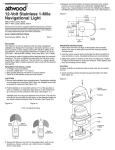
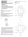
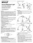
4. Measure and mark location of wire clearance hole. If installing a
bicolor light, location must be on the boat centerline. If installing
a sidelight pair, both must be the same distance from the bow.
3
®
3800 Series Stainless
Steel 2-Mile Sidelights
At the marked location(s), make a mark for a ³⁄₄" hole. This hole is
necessary for wire passage and lamp ventilation (See Figure 2).
Figure 2
Cover Screw
•
Bicolor Combination Bow Light: 3810
Sidelight Pair: 3820
Attwood marine hardware, navigational lighting, bilge pumps, and other
marine accessories are specified more than any other brand by America’s
best-known boat manufacturers as original equipment. Look to Attwood
for quality replacement parts and marine accessories.
•
Lens Cover
•
Lens
SAVE THESE INSTRUCTIONS
Form Number 69360 Rev. A
00-01
FEATURES
The Attwood Stainless Steel sidelights provide 2-mile visibility
with advanced optics for greater visibility and safety. The housing
is corrosion-proof with an aerodynamic design for an attractive
appearance on the deck of your boat. The base gasket forms a
seal between the lens and deck for an easy, waterproof installation.
Side reflectors provide added protection even when the light is not
on. These lights exceed all requirements of ABYC A-16-97 and
COLREG 72 for boats up to 20 meters/65.6 feet (BiColor Bow
Light 3810) and up to 50 meters/164 feet (Sidelight Pair 3820).
#10 Stainless Steel
Mounting Screws
•
O-Ring
•
Base
•
REQUIRED FOR INSTALLATION
• Phillips screwdriver
• Drills: ³⁄₄" for wire clearance hole
Pilot drill for mounting screws
• Two #10 pan head stainless steel screws (not included)
LOCATION
1. Position light(s) on a surface of the gunwale or deck that is
horizontal (within +/-5 degrees).
•
Gasket
2. When installing bicolor combination light, place it on the
centerline of the boat at the bow (See Figure 1a).
When installing sidelight pairs, place lights with the red lens
on the port (left) and green lens on the starboard (right) as you
stand onboard facing bow of the boat. Lights must be parallel
to centerline of the boat (See Figure 1b).
Figure 1a
Red
(Port)
Figure 1b
•
Butt-Joint
Connectors
•
3/4" Hole Aligned
with Boat Centerline
MOUNTING INSTRUCTIONS
1. Remove the cover and lens by removing the Phillips head screw
in the cover and lifting off (See Figure 2).
Green
(Starboard)
Red
(Port)
Green
(Starboard)
2. Align hole beneath light base with the position you’ve marked for
the clearance hole. Set lens toward the bow and align arrow on
base with the boat centerline. Use the light base as a template
to mark locations for the mounting screw pilot holes (use at least
2 #10 stainless steel screws).
CAUTION:
Position holes carefully on aluminum boats so that wires do not
contact the hull.
3. Make sure there are no obstructions at the front or side such as
rail stanchions, chocks, anchors, cleats, etc. within the light’s arc
of visibility (112.5 degrees each side).
3. Drill clearance hole and pilot holes for the mounting screws.
WIRING INSTRUCTIONS
The power supply must be 12-volt DC ONLY. Use crimp type
marine-grade connectors with suitable insulation. Protect all
connections with suitable materials.
NOTE:
Failure to make proper connections and fuse the light properly (see
back page) will void the product warranty.
1. Connect one lead to the negative (-) post of the 12-volt supply.
Connect the other lead to a fused and switched positive (+) 12-volt
supply. Sidelights require 1-amp fusing per lamp: a 1-amp fuse
for the Bicolor Combination light, a 2-amp fuse for the Sidelight
Pair. Note that navigation rules require sidelights to be operated
separately from anchor lights. Use either two switches or a single
switch with three positions for off/anchor/running (See Figure 3).
6. Place stainless steel cover over lens. Be sure gasket is inside
the stainless steel cover at the back. Reinstall screw into cover
(See Figure 5).
Figure 5
Figure 3
Lens Cover
2-Amp Fuse
Switch
Gasket
2. Check gasket to be sure the hole lip is down. Feed wires and
connectors down through the gasket (See Figure 4).
3. Be sure base is seated into the gasket ring all the way around
(See Figure 4 Detail).
4. Align base so the hole lip fits down into the wire clearance hole.
Insert two #10 stainless steel mounting screws and fasten them
to the deck. Note: Do not fasten screws so tightly that the gasket
is deformed.
5. To replace lens: Be sure O-ring is seated on the base screw
mount. Seat lens so the base tabs fit in the lens grooves and
base screw mount lines up with the lens screw hole. Be sure
the gasket is outside the lens at the back.
Figure 4
MAINTENANCE
To replace lamp: Remove the cover screw, cover, and lens.
You may need to pry the lens from the gasket with a small flat
screwdriver, starting in the front of the light.
Remove old lamp by rotating 1/8 turn counterclockwise and pulling
forward. Replace lamp with the proper bayonet bulb (Attwood Part
Number 912717). Check position of O-ring on the base screw mount.
Carefully replace lens and cover on gasket to maintain the waterproof
seal. Reinstall cover screw.
ATTWOOD LIMITED WARRANTY
ATTWOOD CORPORATION, 1016 North Monroe, Lowell, Michigan 49331
(“Attwood”) warrants to the original consumer purchaser that Attwood brand
products will be free from defects in materials and workmanship under normal
use and service for one year from the date of original consumer purchases.
This limited warranty is not applicable if the product has been damaged by
accident, improper installation, unreasonable or improper use, lack of proper
maintenance, unauthorized repairs or modifications, normal wear and tear,
or other causes not arising out of defects in materials or workmanship.
Lens
Lens
Groove
Base Tab
O-Ring
Detail
Base
Gasket
Lens
Gasket
Hole Lip
Attwood products are warranted for use on pleasure boats. Any other use—
including but not limited to commercial, racing, or non-marine use—are not
covered under this warranty. Attwood’s obligation under this warranty is limited
to repair of the product at Attwood’s plant or replacement of the products at
Attwood’s option without expense to the original consumer purchaser. Any
expenses involved in the removal, reinstallation or transportation of the
product are not covered by this warranty.
The product must be returned to Attwood’s plant at the address above,
postage pre-paid, and insured with proof of original purchase including date.
If Attwood is unable to replace the product and repair is not commercially
practical or cannot be timely made, or if the original consumer purchaser
is willing to accept a refund in lieu of repair or replacement, Attwood may
refund the purchase price, less an amount for depreciation. The acceptance
by Attwood of any product returned or any refund provided by Attwood shall
not be deemed an admission that the product is defective or in violation of
any warranty. Products that are replaced or for which a refund is issued
become the property of Attwood.
THIS WARRANTY IS ATTWOOD’S ONLY EXPRESSED WARRANTY OF
THESE PRODUCTS. NO IMPLIED WARRANTY INCLUDING, WITHOUT
LIMITATION, THE IMPLIED WARRANTIES OF MERCHANTABILITY AND
FITNESS FOR A PARTICULAR PURPOSE, SHALL BE EXTENDED BEYOND
THE WARRANTY PERIOD STATED ABOVE FOR EACH PRODUCT.
ATTWOOD SHALL NOT BE LIABLE FOR ANY DAMAGES, FOR LOSS
OF USE OF THIS PRODUCT, NOR FOR ANY OTHER INCIDENTAL OR
CONSEQUENTIAL DAMAGES, COSTS, OR EXPENSES.
Some states do not allow limitations on how long an implied warranty lasts
or the exclusion or limitation of incidental or consequential damages, so the
above limitations and exclusions may not apply to you. This warranty gives
you specific legal rights, and you may have other rights which vary from
state to state.
© 2000
Attwood
Subsidiary Steelcase Inc.
1016 N. Monroe Street, Lowell, MI 49331-0260