1
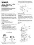
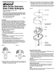
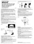
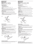
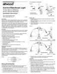
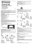
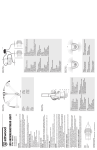
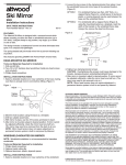
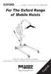
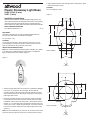
3
®
Plastic Stowaway Light Base
91020, 91022 (2 wire)
91021 (3 wire)
3. Apply sealant between deck and light base. Fasten base in place
with stainless steel screws.
CAUTION
Do not overtighten screws.
Figure 2
Installation Instructions
3/4"
Attwood marine hardware, navigational lighting, bilge pumps, and
other marine accessories are specified more than any other brand by
America’s best-known boat manufacturers as original equipment.
Look to Attwood for quality replacement parts and marine accessories.
SAVE THESE INSTRUCTIONS
Form Number 69345 Rev. C
03-12
FEATURES
This base is designed for use with the Attwood 3900 Series AllRound Lights And Attwood Combination Sidelights.
1"
1-3/4"
1-3/8"
For 12-volt D.C. only.
CAUTION
To prevent personal injury, always disconnect the power source
when installing or servicing this product. Always remove the boat
from the water before using 120 VAC power tools.
INSTALLATION INSTRUCTIONS
Note: For technical detailed positioning follow COLREG 72 or ABYC
A-16. Below is a simplified drawing of placement of navigational
lights in relationship to one another. (Figure 1)
Oval Template
15/32"
15/16"
Figure 1
Forward
1-1/2"
3/4"
27/32"
1. Position the light base either on the bow for combination sidelights
or the stern or gunwale for all-round lights. Be sure that the
mounting surface is flat and that the selected area will accommodate the base dimensions. Base angle and position must properly
place light used in base.
2. Using the template provided, locate the base center line parallel
to the boat fore-and-aft center line and carefully mark the center
installation hole and the screw holes. Drill 1-3/8'' diameter hole for
#91022 or 1-1/4" diameter hole for #91020 and #91021 being very
careful not to crack or break the gelcoat finish, and sand to remove
burrs from around the edge of the hole. Drill the pilot screw holes.
(Figure 2)
1-1/4"
1-1/4"
Round Template
Note: On some installations you may have to connect the wires then
push them back through wire hole prior to screwing down the base.
Forward
FINAL WIRING FOR:
91020, 91022 (2 wire base): Connect one black wire to the battery
ground (-) harness, using a crimp-on wire connector. Attach the
remaining black wire to the positive switched wire from the navigation
light switch.
91021 (3 wire base): Connect black wire to the battery ground (-)
harness, using a wire connector. Connect the blue wire to the wire
from the switch for the courtesy light. Use a wire connector to make
the connection. Connect the gray wire to the wire from the switch for
the navigation running lights using a wire connector.
All positive wires must be fused according to light specs to protect
the circuit. MAKE SURE POWER SOURCE IS 12-VOLT D.C. ONLY.
HIGHER VOLTAGE CAN CAUSE DAMAGE TO LIGHT AND WIRE
CIRCUITRY.
Insert light pole into base and press down to make contact. Insert
lock collar into base opening, rotate if necessary to push it down into
base. Rotate collar until tight to hold light pole in base. Test light
operation. Remove and stow light. Close cover to protect contacts
when not in use.
Part #91020, 91021
Part #91022
This product carries the standard Attwood one-year limited
warranty. See product catalog for details.
© 2003 Attwood Corporation
1016 N. Monroe Street, Lowell, MI 49331-0260 www.attwoodmarine.com