1
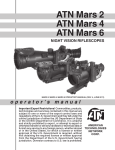
ATN Mars x4
ATN Mars x6
u s e r ` s
g u i d e
Important Export Restrictions! Commodities, products, technologies and services contained in this manual
are subject to one or more of the export control laws and
regulations of the U.S. Government and they fall under the
control jurisdiction of either the US Department of State
or the US BIS-Department of Commerce. It is unlawful
and strictly prohibited to export, or attempt to export or
otherwise transfer or sell any hardware or technical data
or furnish any service to any foreign person, whether
abroad or in the United States, for which a license or written approval of the U.S. Government is required, without
first obtaining the required license or written approval
from the Department of the U.S. Government having
jurisdiction. Diversion contrary to U.S. law is prohibited.
American
Technologies
Network
Corp.
MARS X4
Lens cap
Focus adjustment
knob
Windage
Elevation
Sensor of system
of automatic brightness control
F1:1.5 lens
Reticle brightness
adjustment knob
Remote
control
-6/+2 Diopter
Mounting
system
Battery
housing
Picatinny
rails
MARS X6
Battery
housing
Fixation
screw
Operation
switch
IR brightness
adjustment
IR elevation
IR focusing
Digital InfraRed Illuminator
IR windage
Features
• POWERFUL 4X OR 6X MAGNIFICATION
• SUPERIOR QUALITY MULTI-COATED ALL
GLASS OPTICS
• “SINGLE-ELEMENT” ADJUSTABLE FRONT
FOCUS
• NITROGEN-PURGED FOR RESISTANCE
TO INTERNAL FOGGING
• MIL-DOT RETICLE
• CRISP-CLICK PRECISION WINDAGE AND
ELEVATION ADJUSTMENTS
• TARGET TURRETS
• AUTOMATIC BRIGHTNESS CONTROL
• TACTICAL RAIL ENABLING MOUNTING OF
IR ILLUMINATOR OR IR LASER
• LOW BATTERY INDICATOR
• TACTICAL DIGITAL REMOTE CONTROL
• WATERPROOF AND SUBMERSIBLE TO 66
FEET FOR 1 HOUR
• PELICAN HARD CASE, BATTERIES, USER
GUIDE, NV INSTRUCTIONAL VIDEO AND
ALL NECESSARY MOUNTING HARD WARE ARE INCLUDED
• INCLUDED MOUNT FOR PICCATINY OR
7/8” WEAVER-STYLE RAIL
(M4/M16/AR-15 CARRY HANDLE MOUNT
– OPTIONAL)
• UNIT ACCEPTS EITHER, (1) 3V CR123A OR
(1) AA BATTERY
• DAY TIME COVER WITH IR FILTER
• LIMITED LIFETIME WARRANTY
Application
ATN Mars Night Vision Weapon scopes - the world’s largest line of professional night vision
sights – has a new flagship – the ATN MARS X4 and ATN MARS X6. Inspired by ATN’s quest
for technical perfection and named after the Roman God of War, the ATN MARS NV riflescopes represent the absolute latest in the world of night vision equipment. Similar to all ATN
Aries scopes the ATN MARS features only the purest grades of heavy glass and computeraided optical designs to create multi-element, high-speed, multi-coated lenses for ultra-fast
light transmission and resolution beyond current military standards. All optical lenses on the
MARS scopes are individually fitted and calibrated to achieve optimum performance.
The information in this manual furnished for information use only, is subject to change without notice, is not to be
construed as a commitment by ATN Corp.
ATN Corp. assumes no responsibility or liability for any errors or inaccuracies that may appear in this book.
©2006 ATN Corp. All right reserved.
Specifications
MARS X4
2nd, 2nd+, 3rd, 4th
Generation .............................
F1:1.5
Lens of system ..........................
4X
Magnification ..........................
9 deg.
FOV ..........................................
10 m to ∞
Range of focus .........................
45mm
Eye relif .....................................
7mm
Exit pupil ...................................
-6/+2
Diopter adjustment ...............
120MOA
Windage & elevation ................
1/4MOA
Adjustment step size ..............
Power supply ........................ one 3V (CR123A) or 1.5V (AA)
Super 450mW
IR illuminator ............................
-51°C to +45°C
Operating temperature .......
55 (3V)/ 40 (1.5V )hours
Battery life................................
20m for 1 hour
Waterproof ...............................
Reticle .................................... Red or Amber On Green
235x90x95mm
Dimensions .............................
1.3kg
Weight ....................................
MARS X6
2nd, 2nd+, 3rd, 4th
F1:2.0
6X
6 deg.
25 m to ∞
45mm
7mm
-6/+2
80MOA
1/6MOA
one 3V (CR123A) or 1.5V (AA)
Super 450mW
-51°C to +45°C
55 (3V)/ 40 (1.5V )hours
20m for 1 hour
Red or Amber On Green
295x95x100mm
1.55 kg
Preparation for operation
Before getting started make sure to follow these steps:
• Install the battery into its housing with the polarity order
shown on the main body of the unit. The CR123A battery
used with adapter. Install adapter first, then CR123A . AA
battery used without adapter.
• Switch on the scope with the protective lens cover still
attached to the lens.
• Make sure that the green luminance of the light intensifier
tube is present.
• Observe the scene, and adjust the diopter and/or lens for
optimal image clarity.
• You may now enter a dark environment or simply shut the
lights off in order to darken the room.
• Next, remove the lens cap/daylight filter.
Battery cap
Battery cap
CR123A
battery
AA
battery
Battery
adapter
OPERATING
MOUNTING
1. Mount the PS-22 with Adapter onto the A.R.M.S.#10 or A.R.M.S.#19 ACOG with 2 screws M5x8.
2. Unscrew the protective back cap from PS-22.
3. Screw the Light Screen into the thread in back side of unit.
4. Slightly loosen the fixing screws or levers of mount.
5. Place the PS-22 on the weaver rail of the fire arm before objective of daytime scope on the
minimal distance from it. The optical axes of PS-22 and daytime scope must have diver
gence not more than 3mm. High of optical axe of the PS-22 under weaver rail is 49mm with
A.R.M.S.#19 ACOG.
6. Tighten the fixing screws or levers of mount.
NOTE: Fixing screws may need to be tightened after continuous shooting.
COntrol
To turn the device on, rotate the Operation Switch from the OFF position to the desired operation mode.
Operation Switch has following positions/modes:
OFF - the device is off;
ON – the device is on;
STB - the device can be used with the Remote Control.
FOCUSING
To focus the scope you need to adjust the diopter first. Simply turn the diopter clockwise until it
stops. Then concentrate on any object and slowly turn the diopter back
Focus adjustment knob
counter clockwise until the grain in the image is sharp.
You scope has ability to focus either long range or short.
Focus the front lens by rotating the knob until the image and the grain
are both sharp. When you are in the low-light conditions and the daylight filter is off you may focus the front lens to receive a sharp image,
the diopter should not be adjusted.
NOTE: The front lens should be readjusted for viewing objects at different distances.
automatic brightness control System
The device has a built in Automatic brightness control. This control automatically adjusts the
brightness of Image Intensifier Tube to the optimal level. Protective system
The automatic highlight protective system analyzes light exposure with the sensor . If the level of light exposure exceeds allowable the red indicator will lights on. If high light exposure is
kept more than 10 seconds the device automatically will off.
NOTE: The automatic highlight protective system and automatic brightness control system do not protect a sight from damage
by bright light sources (a fire, headlights of the automobile, lanterns, etc.). Do not point the device at a bright light source.
Sensor
IR Illumination
Infra-red (IR) Illuminators are common for night vision technology. The IR light greatly
enhances the performance of your scope, while remaining almost totally invisible to the naked
eye. In dark environment, power up the scope. Now, find a scene and examine it without the IR
on then with IR powered up. Note the difference in illumination. It is important to remember that
Battery
Housing
IR Brightness
Adjustment
IR Elevation
IR Focusing
Nut
Fixation
Screw
IR Windage
the IR illuminator is simply an infra red light source, and like any light source it may loose its
effectiveness over a great distance.
To fix the IR illuminator to the riflescope use the picatinny raile of the scope.
The IR illuminator control buttons are located on its side. To switch the Digital IR illuminator
on/off press “+” and “-” buttons simultaneously. When the IR illuminator is switched on you can
see the green LED lit. By pushing the buttons “+” and “-” you may adjust the IR brightness.
The IR beam is focusable to change the field of coverage. To change the beam width slightly
turn the IR lens.
You could change the IR control panel fitting your needs. The wrench included into the set
should be used for weakening the fixing nut located on the IR. Rotate the IR placing at in the
most convenient position. Tighten the nut with the wrench to fix the new position.
REmote control
Attach the Remote Control cable to connector on the bottom of
the body of device. Place the Remote Control on the weapon,
suiting your shooting style best and grip. Fix the Remote Control
in this position with a montage strap.
To turn the scope on push the button of remote control. Keep
pressed button when observing scene. The scope is turned off
immediately after releasing remote control button.
low Battery indicator
When red LED on left side of the field of view starts blinking it is time to change your battery.
RETICLE
Your scope has an Electronic reticle with two color and 5 degrees of brightnes of illumination
for each color. The knob of brightnes ajustment reticle and color select is located on the top of
the boby of the scope. On the knob there are marking with color of illumination of reticle.
Mil dot reticle is a reliable means of determining distances to targets, establishing leads for moving tar1 mil
gets, and for alternate aiming points for windage and
elevation holds.
Dots are spaced in one mil (milliradian) increments
1 mil
on the crosshair. A distance to target can be calculated using the mil formula, that is based on the size
of the object being targeted.
Look through the scope, and bracket the object between dots.
The space between dot centers subtends one milliradian(mil). One mil. subtends 3.6 inches
at 100 yards or 36 inches at 1,000 yards. To use this system effectively you must know the size
of the target.
By measuring the height or width of a known (or approximately known target size) in mil-radians using the reticles, the target distance can be calculated as follows.
R = range in meters, H = target size in meters, M = mil-radians of the image size:
R = 1000 * H / M
Military shooters are trained to know that the common male torso is 39 inches from crotch to top of
head. This is very close to exactly one meter.
This formula then becomes R = 1000 / M for a one meter target size.
All of the following formulae are equivalent to the one above for estimating range.
R = range in meters, H = target size in inches, M = mil-radians of the image: R = 25.4 * H / M
R = range in yards, H = target size in inches,
M = mil-radians of the image: R = 27.78 * H / M
R = range in yards, H = target size in feet,
M = mil-radians of the image: R=333.3 * H / M
WINDAGE AND ELEVATION
Elevation
The vertical and horizontal adjustments for the scope can be
achieved by turning the elevation and windage adjustment mechanisms (remove dust caps first). Each click equals 1/4 inch at 100
yards (Mars x4) or 1/6 nch at 100 yards (Mars x6) . When reaching
the maximum range of rotation do not use force.
Windage
WARNINGS AND CAUTIONS
• Always remember to turn off the scope when it is not in use. If you do not plan on using your
scope for a period of more than 10 days, you should remove the batteries.
• Keep lens cap on when not in use.
• Avoid contact with dust, steam, and gas.
• The scope are not harmful to the user or the environment.
• Do not disassemble: it will void your warranty.
• Evaluate the scopes function by looking through it in a lit environment with the lens cap put
on. Never use in daylight without the daylight filter lens cap on. Do not surpass ten minutes
of testing.
• Never point the scope at a bright light source.
• Adverse atmospheric conditions such as fog, smog, or haze and a lack of ambient light
(moon or starlight) may diminish the effective viewing distance. All technical data for this unit
was compiled in a controlled environment.
• If you use the rubber eyecaps for a long period of time, you may suffer skin inflammation. If
you develop any symptoms, consult a doctor immediately.
TROUBLEsHOOTING
Q: Flashes, flickers, or clicking occur while operating
S: If it occurs within the first five minutes of inserting new batteries, it is normal and the device
will resume normal operation soon thereafter. If it occurs for more than 10 minutes, contact
your dealer or other authorized service representative for service instructions.
Q: Dark spots on screen.
S: This may be dust on the lens, please clean according to instrutions. They may also be Cosmetic blemishes in the intensifier tube which are a by-product of the manufacturing process.
This is normal and will not affect the life or performance of the unit.
Q: Image not clear.
S: Adjust diopter ring. If problem persists, increase viewing distance
Q: Fixed-pattern noise in a honeycomb shape.
S: Usually a cosmetic blemish characterized by a faint honeycomb-type pattern. This usually
occurs when viewing very bright lights.
Q: A pattern of dark thin lines which look like chicken wire.
S: Turn on illuminator, if purchased. If illuminator doesn’t brighten image, replace batteries. If
problem persists, contact ATN for service instructions.
Warranty
LIFETIME LIMITED PRODUCT WARRANTY
This product comes with a Lifetime Guarantee against defects in both materials and workmanship. In the
event a defect that is covered by the foregoing warranty occurs during the applicable period stated above,
ATN, at its option, will either repair or replace the product, and such action on the part of ATN shall be the
full extent of ATN’s liability, and the Customer’s sole and exclusive remedy. This warranty does not cover
a product (a) used in other than its normal and customary manner; (b) subjected to misuse, (c) subjected
to alterations, modifications or repairs by the Customer of by any party other than ATN without prior written
consent of ATN; (d) special order or “close-out” merchandise or merchandise sold “as-is” by either ATN
or the ATN dealer; or (e) merchandise that has been discontinued by the manufacturer and either parts
or replacement units are not available due to reasons beyond the control of ATN. ATN shall not be responsible for any defects or damage that in ATN’s opinion is a result from the mishandling, abuse, misuse,
improper storage or improper operation, including use in conjunction with equipment which is electrically
or mechanically incompatible with or of inferior quality to the product, as well as failure to maintain the
environmental conditions specified by the manufacturer. This warranty is extended only to the original
purchaser. Any breach of this warranty shall be waived unless the customer notifies ATN at the address
noted below within in the applicable warranty period.
THE CUSTOMER UNDERSTANDS AND AGREES THAT EXCEPT FOR THE FOREGOING WARRANTY,
NO OTHER WARRANTIES WRITTEN OR ORAL, STATUTORY, EXPRESSED OR IMPLIED, INCLUDING
ANY IMPLIED WARRANTY OF MERCHANTABILITY OR FITNESS FOR A PARTICULAR PURPOSE,
SHALL APPLY TO THE PRODUCT. ALL SUCH IMPLIED WARRANTIES ARE HEREBY AND EXPRESSLY DISCLAIMED.
LIMITATION OF LIABILITY
ATN will not be liable for any claims, actions, suits, proceedings, costs, expenses, damages or liabilities
arising out of the use of this product. Operation and use of the product are the sole responsibility of the
Customer. ATN’s sole undertaking is limited to providing the products and services outlined herein in accordance with the terms and conditions of this Agreement. The provision of products sold and services
performed by ATN to the Customer shall not be interpreted, construed. 01 regarded, either expressly or
implied. as being fur the benefit of or creating any obligation toward any third party of legal entity outside
ATN and the Customer: ATN’s obligations under this Agreement extend solely to the Customer. ATN’S
LIABILITY HEREUNDER FOR DAMAGES. REGARDLESS OF THE FORM OR ACTION, SHALL NOT
EXCEED THE FEES OR OTHER CHARGES PAID TO ATN BY THE CUSTOMER OR CUSTOMER’S
DEALER. ATN SHALL NOT, IN ANY EVENT, BE LIABLE FOR SPECIAL, INDIRECT, INCIDENTAL. OR
CONSEQUENTIAL DAMAGES. INCLUDING. BUT NOT LIMITED TO. LOST INCOME, LOST REVENUE.
OR LOST PROFIT. WHETHER SUCH DAMAGES WERE FORESEEABLE OR NOT AT THE TIME OF
PURCHASE. AND WHETHER OR NOT SUCH DAMAGES ARISE OUT OF A BREACH OF WARRANTY,
A BREACH OF AGREEMENT, NEGLIGENCE, STRICT LIABILITY OR ANY OTHER THEORY OF LIABILITY.
PRODUCT WARRANTY REGISTRATION
In order to validate the warranty on your product, ATN must receive a completed Product Warranty Registration Card for each unit. Please complete me form below and immediately mail it
to our Service Centre: ATN Corporation, 20 South Linden Ave. Suite 1B, South San Francisco,
CA 94080. Products qualifying for warranty repair will be either repaired or replaced within 10 business
days of receipt of merchandise unless the customer is notified otherwise.
OBTAINlNG WARRANTY SERVICE
To obtain warranty service on your unit, take or send the product, postage paid, with a copy of our sales
receipt to our service centre, ATN Corporation at the address noted above. All merchandise must be fully
insured with the correct postage; ATN will not be responsible for improper postage, or, missing or damaged merchandise during shipment.
For customer service and technical support, please contact
American Technologies Network Corp.
North American Office
20 S. Linden Ave. Suite 1B, South San Francisco, CA 94080
phone: 800-910-2862, 650-875-0130; fax: 650-875-0129
European Office
phone: 44(0)870-0111286, fax: 44(0) 845-3349142
The following countries can use our
toll free number 00 800 9102-8620
Austria, France, Germany, Holland, Italy, Spain, Sweden, Switzerland
www.atncorp.com
©2006 ATN Corporation