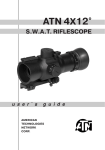
1
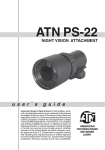
ATN PS-22
NIGHT VISION ATTACHMENT
u s e r ` s
g u i d e
Impor tant E xpor t Restrictions ! Commodities,
products, technologies and services contained in
this manual are subject to one or more of the export
control laws and regulations of the U.S. Government
and they fall under the control jurisdiction of either the
US Department of State or the US BIS-Department
of Commerce. It is unlawful and strictly prohibited
to export, or attempt to export or otherwise transfer
or sell any hardware or technical data or furnish any
service to any foreign person, whether abroad or
in the United States, for which a license or written
approval of the U.S. Government is required, without
first obtaining the required license or written approval
from the Department of the U.S. Government having
jurisdiction. Diversion contrary to U.S. law is prohibited.
REMOTE
CONTROL
CAP
FAST CATADIOPTIC
FRONT LENS
SYSTEM WITH
MULTI-COATED ALL
GLASS OPTICS
FOCUSING RING
BATTERY CAP
FRONT LENS CAP/
DAYLIGHT FILTER
REMOTE CONTROL
OPERATION SWITCH
RUBBER LIGHT
SUPPRESSOR
7/8" WEAVER MOUNT
A.R.M.S. ADAPTER
(OPTIONAL)
Day scope light
suppressor (OPTIONAL)
ATN PS-22 with ATN 5x33L and IR 450
(with 7/8" weaver mount and platform
ring for IR450)
ATN PS-22 with ATN 5x33L and IR 450
(with Scope Mounting System and picatinny
rail for IR illuminator)
ATN PS-22 with Trijicon daytime scope
(with 7/8" weaver mount)
BACK CAP
PICATINNY RAIL
PLATFORM RING
(OPTIONAL)
IR ILLUMINATOR
IR450
SCOPE MOUNTING
SYSTEM (OPTIONAL)
ATN PS-22 with ATN 3,5x26 and IR 450
(with Scope Mounting System)
ATN PS-22 with Leupold daytime scope
(with the 7/8" weaver mount)
ATN PS-22 with a spotting scope
The information in this manual furnished for information use only, is subject to change without notice, is not to be construed
as a commitment by ATN Corp.
ATN Corp. assumes no responsibility or liability for any errors or inaccuracies that may appear in this book.
©2009 ATN Corp. All right reserved.
Application
The PS-22 is an attachment for daytime scopes with 1x-6x (2.5x-4x are optimal) magnification that converts
the scope into a high quality compact night vision scope .
The PS-22 mounts in front of a daytime scope. Re-zeroing of a scope is not required. PS-22 comes with a
standard 7/8” weaver mount. There is also A.R.M.S. Adapter (optional) for A.R.M.S. quick release mount.
Optional Scope Mounting System allow to mount the unit onto the objective of a day scope with 25-58mm
diameter. The powerfull IR450 illuminator can be mounted onto the Picatinny Rail.
The PS-22 utilizes a 2nd Gen.+ or 3rd Gen. Image Intensifier Tube. This ingenious scheme allows the
shooter to go from day to night in less then 30 seconds without tools, without changes in eye relief remaining zeroed all around the clock.
The PS-22 is a complex optical-electronic system. The device contains an image intensifier tube assembly
with an integrated high voltage power source and a three volt battery housing.
Objective lens protective cover is intended to protect objective lens from dust, scratches and high-level
illumination. The pinhole in cover allows the user to check the operation ability of the device in highlight
conditions.
The device has a built in Automatic Brightness Control. This system automatically adjusts the brightness of
Image Intensifier Tube to the optimal level.
Features
• Easily changes daytime scope to Night Vision
• Mounts in front of daytime scope, no re-zeroing required
• Available in 2nd + and 3rd generation
• Multi-coated all glass optics
• Fast catadioptic front lens system
• 21mm output window
• Light weight and rugged
• Tactical Digital Remote Control
• Comes with a standard 7/8” weaver mount
• Optional A.R.M.S. Adapter for A.R.M.S. quick release mount included
• Optional Scope Mounting System for mounting onto the objective of the day scope (25-62 mm diameter)
Specifications
Magnification........................................................................................................................................... 1X
Intensifier Tube...........................................................................................................2nd Gen+ or 3rd Gen
Lens System....................................................................................................................... F1:1.44, 80mm
FOV........................................................................................................................................................ 13°
Power Supply.................................................................................................. one 3 Volt Battery(CR123A)
Range Of Focus....................................................................................................................10 m to Infinity
Battery Life...................................................................................... 60 hours (Gen.2+); 50 hours (Gen.3)
Operating Temperature ..................................................................................................... -40°C to +50°C
Storage Temperature ......................................................................................................... -50°C to +70°C
Dimensions......................................................................................................... 139mm X 80mm X 72mm
Weight.................................................................................................................................................0.6kg
* ATN reserves the right to change the above specifications at any time without notice
Cau tion :
This product contains natural rubber latex which may cause allergic reactions.
2
2
mounting
3
C
A
D
B
1 1
B
Mounting onto the Weaver rail with 7/8” Weaver
Mount
1) Mount the 7/8” Weaver Mount (A) onto the body
of PS-22 with two screws M4x7 (B) from the kit.
2) Unscrew the protective back cap from PS-22.
3) Screw the Rubber Light Suppressor (C) into the
thread at the PS-22 back side.
4) Loosen slightly the fixing screws (D) of the
mount.
5) Place the PS-22 onto the weaver rail (E) of
the fire arm before objective of daytime scope at
the minimal distance from it. The optical axis of
PS-22 must have divergence with the optical axis
of daytime scope not more than 3mm. The height
of PS-22 optical axis over the weaver rail is equal
to 40mm with a standard mount that also matches
ATN 3.5x26 scope.
6) Tighten the fixing screws (D).
NOTE: Fixing screws may need to be tightened
again after continuous shooting.
5
E
D
E
4
A
C
B
B
1
F
3
D
2
2
1
D
Mounting onto the Weaver rail with A.R.M.S.
Mount
1) Mount the A.R.M.S. Adapter (optional) (A) onto
the body of PS-22 with two screws M4x7 (B) from
the kit.
2) Mount the PS-22 with A.R.M.S. Adapter onto
the A.R.M.S.#10 or A.R.M.S.#19 ACOG (C) with
two screws M5x8 (D).
3) Unscrew the protective back cap from PS-22.
4) Screw the Rubber Light Suppressor (E) into the
thread at the PS-22 back side.
5) Loosen slightly the fixing screws or levers (F) of
the mount.
6) Place the PS-22 onto the weaver rail of the
fire arm before objective of daytime scope at the
minimal distance from it. The optical axis of PS-22
must have divergence with the optical axis of
daytime scope not more than 3mm. The height
of PS-22 optical axis over the with A.R.M.S.#19
ACOG is equal to 49mm.
7) Tighten the fixing screws or levers (F) of mount.
NOTE: Fixing screws may need to be tightened
again after continuous shooting.
4
2
C
A
5
Mounting onto the objective of the day scope
with Scope Mounting System
1) Unscrew the protective back cap from PS-22.
2) Screw the Scope Mounting System body (A) into
the thread at the PS-22 back side.
3) Slightly loosen the fixing screw (B) of the Scope
Mounting System.
4) Put the Insert (C) with the required diameter*
into the System's body.
5) Slide the PS-22 with the Scope Mounting System to the objective of a day scope.
6) Tighten hard the fixing screw (B) of the Scope
Mounting System.
Mounting Picatinny Rail and IR450
1) Mount Picatinny Rail (A) onto the body of PS-22 with two screws M4x7 (B) from the kit.
2) Place IR Illuminator (C) onto the Picatinny Rail.
B
A
C
TABLE 1. SCOPE MOUNTING SYSTEM PARAMETERS AND SCOPE EXAMPLES
Scope Mounting System #
1
2
3
4
6
Diameter of the Scope Objective
(Insert Size)
25.4 mm
30 mm
38 mm
42 mm
46.7 mm
48 mm
from 48.7 to 49.0 mm
49.5 mm
50 mm
56 mm
57 mm
58.7 mm
62
Examples of Scopes
Leupold 1.5-5x20 PR
Leupold 1.5-5x20 MR/T M2; Zeiss 1.1-4x24 T
Meopta Artemis 2000 4x32
Leupold Mark 4 3-9x36; Leupold Mark 4 2.5-8x36;
Kahles 4x36
Leupold 3.5-10x40; Leupold VX-II 3-9x40
Zeiss 1.5-6x42; Swarovski PV-N 2.5-10x42
Meopta Artemis 3000 3-9x42
Meopta Artemis 3000 4-12x40
Schmidt@Bender 10x42 PMII
Zeiss 2.5-10x50
Schmidt@Bender 3-12x50
Leupold 4.4-14x50; Leupold VX-III 3.5-10x50
Zeiss 3-12x56; Swarovski 2.5-10x56;
Kahles CSX 3-12x56
CAUTION: Never use an Insert with the Scope Mounting System that do not correspond each other
(are in different rows) at the Table 1.
How to select Scope Mounting System required for your daytime scope
Owing to Scope Mounting Systems (with Inserts) having different diameters you can mount PS-22 Attachment onto a daytime scope with objective tube diameter from 25 to 62 mm the way the tube glowing
will be absolutely invisible for others. At the Table 1 Scope Mounting System sizes (#1-6) and Insert
sizes for different scope examples are provided.
You may not find your daytime scope (and Scope Mounting Systems with Insert needed) at the Scope
Examples column. In this case, before mounting procedure you have to select Scope Mounting System
(and Insert) required for your daytime scope. To do this perform the following actions:
4
1) Determine your daytime scope objective tube diameter (external - not diameter of the glass lens!) with a millimeter ruler
(with a trammel for more accurate results) as shown at the picture.
2) Select from the Table 1 the Insert size closest (larger) to the
value measured (Insert size is also specified at an Insert body).
Do the selection in Insert group that corresponds to the same
Scope Mounting System (for example, Scope Mounting System
#2).
3) The Scope Mounting System you need is the one that corresponds to Insert size selected at the Table 1.
For example, if your scope objective tube diameter is equal to 46
mm then you should select Insert with size of 46,7 mm and corresponding Scope Mounting Systems #3 from the Table 1.
Platform Ring
IR Illuminator can be mounted not only onto
PS-22 with Picatinny Rail Adapter but also onto a
daytime scope using optional Platform Ring. To
perform this do the following:
1) Unscrew the two screws set (A) from the Platform Ring.
2) Place the top and lower parts of the Platform
Ring around your daytime scope tube (B), as
shown on the picture.
3) Tighten hard the two screws set (A).
A
A
B
Daytime Scope Light Suppressor
There is a rubber Daytime Scope Light Suppressor (DSLS). The DSLS slides over the eyepiece of
your daytime scope.
The DSLS was designed to achieve several missions:
1) Prevent back glow from the device that could give away position
2) Prevent surrounding light from interfering with image on eyepiece
The DSLS can be adjusted for the eye relief of your scope by cutting the rubber at the desired distance.
Operation
Place the PS-22 before objective of daytime scope.
Make sure the power switch is at the OFF-position.
Install the battery into the housing with the polarity order shown at the devices body. The battery is 3 volt lithium battery (CR123A).
To turn the device on, draw and rotate the operation switch to the ON-position. The greenish-lit screen of the image tube (when looking through the
eyepiece) means that the image tube is powered on.
Do not turn the unit on during daytime without the protective lens cap/ daylight filter on.
5
NOTE: The protective lens cap has several small holes in it to allow it to be used as a daylight filter.
When using this as a daylight filter you will notice a double vision, this is normal due to the catadioptic
lens system.
Next move to a dark environment and remove the lens cap.
Observe the scene and adjust the focusing of PS-22 by rotation the focusing ring. Also focus the daytime scope for optimal clarity.
Turn on the illumination of daytime scope reticle (if any) and adjust its brightness (see your daytime
scope's user manual).
To turn the PS22 off, draw and turn the operation switch to the OFF-position.
REmote control
Attach the Remote Control cable to connector on the side of the body of device. Place the Remote Control
on the weapon, suiting your shooting style best and grip. Fix the Remote Control in this position with a
montage strap.
For using the device with Remote control, rotate the Operation Switch from the OFF position to STB position. To turn the device on push the button of remote control. Keep pressed button when observing scene.
The scope is turned off immediately after releasing remote control button.
To switch the Remote Control mode OFF rotate the Operation Switch from the STB position.
IR Illuminator
The IR illuminator greatly enhances the performance of your PS22, while remaining almost totally invisible to the naked eye.
NOTE:It is important to remember that the IR illuminator is simply an infra red light source, and like any
light source it may loose its effectiveness over a great distance.
IR450 illuminator is mounted onto the picatinny rail.
The IR illuminator control buttons are located on its side. To switch the Digital IR illuminator
on/off press “+” and “-” buttons simultaneously. When the IR illuminator is switched on you can see the
green LED lit. By pushing the buttons “+” and “-” you may adjust the IR brightness.
The IR beam is focusable to change the field of coverage. To change the beam width slightly turn the
IR lens.
You could change the IR control panel fitting your needs. The wrench included into the set should be
used for weakening the fixing nut located on the IR. Rotate the IR placing at in the most convenient
position. Tighten the nut with the wrench to fix the new position.
Battery Housing
IR Brightness Adjustment
IR Elevation
IR Focusing
Nut
Fixation Screw
IR Windage
6
WARNINGS AND CAUTIONS
• Do not forget to turn off the PS-22 when it is not in use. If you do not plan to use your unit for a period
of more than 10 days, you should remove the batteries.
• Keep lens cap on when PS-22 is not in use.
• Avoid contact with dust, steam, and gas.
• The PS-22 is not harmful for its user or environment.
• Do not disassemble: it will void your warranty.
• Never use in daylight conditions without the lens cap on.
• Never point the PS-22 at a bright light source. If the device shuts off automatically after directing it
at a bright light source, turn the unit off and wait for 1-2 minutes before turning the unit back on.
• Adverse atmospheric conditions such as fog, smog, or haze and a lack of ambient light (moon or
starlight) may decrease the effective viewing distance. All technical data for this unit was compiled in
a controlled environment.
• If you use the rubber eyecaps for a long period of time, you may suffer skin inflammation. If you develop any symptoms, consult a doctor immediately.
TroubleshoOting
Q: Flashes, flickers or clicking occur while operating
S: If it occurs within the first five minutes of inserting new batteries, it is normal and the device will
resume normal operation soon thereafter. If it occurs for more than 10 minutes, contact for service
instructions.
Q: Dark spots on screen.
S: These are either cosmetic blemishes in the intensifier tube or dust particles.
Q: Screen becomes darker than at previous use.
S: Replace batteries. If problem persists, contact your dealer or other authorized service representative for service instructions.
Q: Image not clear.
S: Adjust objective lens, and/or the eyepiece.
Tube Maintenance / Replacement
Tube maintenance/replacement is to be performed by qualified technicians only. These procedures attempted by non-qualified personnel will void warranty.
1) Loosen slightly (do not remove completely) three set screws (1) at the Objective Locking Ring side (2).
2) Unscrew the Objective Locking Ring (2) and the Objective Focusing Ring (3).
3) Unscrew the Objective Directive Screw (4).
5) Disassemble the Objective (5) from the Body (6).
6) Unscrew the IIT Locking Ring (7) from the Body.
7) Replace IIT (8) with another one. During this step pay attention to Locking-finger (9) that must consist with the groove in IIT body.
8) Do the steps 1-7 mentioned above in reverse order to assemble the PS-22.
7
2 Year product Warranty
This product is guaranteed to be free from manufacturing defects in material and workmanship under
normal use for a period of 2 (two) years from the date of purchase. In the event a defect that is covered
by the foregoing warranty occurs during the applicable period stated above, ATN, at its option, will
either repair or replace the product, and such action on the part of ATN shall be the full extent of ATN’s
liability, and the Customer’s sole and exclusive remedy. This warranty does not cover a product (a)
used in other than its normal and customary manner; (b) subjected to misuse; (c) subjected to alterations, modifications or repairs by the Customer of by any party other than ATN without prior written
consent of ATN; (d) special order or “close-out” merchandise or merchandise sold “as-is” by either
ATN or the ATN dealer; or (e) merchandise that has been discontinued by the manufacturer and either
parts or replacement units are not available due to reasons beyond the control of ATN. ATN shall not
be responsible for any defects or damage that in ATN’s opinion is a result from the mishandling, abuse,
misuse, improper storage or improper operation, including use in conjunction with equipment which
is electrically or mechanically incompatible with or of inferior quality to the product, as well as failure
to maintain the environmental conditions specified by the manufacturer. CUSTOMER IS HEREBY
NOTIFIED THAT OPERATION OF THE EQUIPMENT DURING DAYLIGHT HOURS OR UNDER
ANY EXCESSIVE LIGHT CONDITIONS MAY PERMANENTLY DAMAGE THE INTERNAL COMPONENTS OF THE UNIT AND SAID DAMAGE WILL NOT BE COVERED UNDER THIS WARRANTY.
This warranty is extended only to the original purchaser. Any breach of this warranty shall be waived
unless the customer notifies ATN at the address noted below within the applicable warranty period.
The customer understands and agrees that except for the foregoing warranty, no other warranties
written or oral, statutory, expressed or implied, including any implied warranty of merchantability or
fitness for a particular purpose, shall apply to the product. All such implied warranties are hereby and
expressly disclaimed.
Limitation of liability
ATN will not be liable for any claims, actions, suits, proceedings, costs, expenses, damages or liabilities arising out of the use of this product. Operation and use of the product are the sole responsibility of
the Customer. ATN’s sole undertaking is limited to providing the products and services outlined herein
in accordance with the terms and conditions of this Agreement. The provision of products sold and
services performed by ATN to the Customer shall not be interpreted, construed, or regarded, either
expressly or implied, as being for the benefit of or creating any obligation toward any third party of legal
entity outside ATN and the Customer; ATN’s obligations under this Agreement extend solely to the Customer. ATN’s liability hereunder for damages, regardless of the form or action, shall not exceed
the fees or other charges paid to ATN by the customer or customer’s dealer. ATN shall not, in
any event, be liable for special, indirect, incidental, or consequential damages, including, but
not limited to, lost income, lost revenue, or lost profit, whether such damages were foreseeable
or not at the time of purchase, and whether or not such damages arise out of a breach of warranty, a breach of agreement, negligence, strict liability or any other theory of liability.
Product warranty registration
In order to validate the warranty on your product, ATN must receive a completed Product Warranty
Registration Card for each unit or complete warranty registration on our website at www.atncorp.com.
Please complete the included form and immediately mail it to our Service Center: ATN Corporation,
1341 San Mateo Avenue, South San Francisco, CA 94080.
12052009
Obtaining warranty service
To obtain warranty service on your unit, End-user must notify ATN service department by calling
800-910-2862 or 650-989-5100 or via e-mail [email protected] to receive a Return Merchandise Authorization number (RMA). When returning please take or send the product, postage paid,
with a copy of your sales receipt to our service center, ATN Corporation at the address noted above. All
merchandise must be fully insured with the correct postage; ATN will not be responsible for improper
postage or, missing or damaged merchandise during shipment. When sending product back, please
clearly mark the RMA# on the outside of the shipping box. Please include a letter that indicates your
RMA#, Name, Return Address, reason for service return, Contact information such as valid telephone
numbers and/or e-mail address and proof of purchases that will help us to establish the valid start date
of the warranty. Product merchandise returns that do not have an RMA listed may be refused or a
significant delay in processing may occur. Estimated Warranty service time is 10-20 business days.
End-user/customer is responsible for postage to ATN for warranty service. ATN will cover return postage/shipping after warranty repair to end-user/customer only if product is covered by aforementioned
warranty. ATN will return product after warranty service by domestic UPS ground and/or domestic mail.
Any other requested or required shipping method the postage/shipping fee will be the responsibility of
the end-user/customer.
8
APPENDIX A
spare PARTS LIST
The Spare Parts List is an illustrated catalog of main parts and assemblies completing the Night Vision
Attachment PS-22, here in after referred to as PS-22.
Therefore, in case of failure of any part or assembly User could replace it by ordering the corresponding
part/assembly from the Spare Parts List. The amount and assortment of the spare parts needed should
be arranged with each contract individually.
TABLE A1. ATN PS-22 spare Parts List
PART NO.
DESCRIPTION
FIG.
ITEM
AT 146531.700
Attachment
A1
AT 146531.701
Front Lens Cap
A1
1
AT 146531.702
Objective Assembly
A1
2
AT 146531.704
Objective Directive Screw
A1
3
AT 146531.705
Body (with Objective Focusing and Locking Rings)
A1
4
Lithium Battery CR123A
A1
5
AT 146531.706
Battery Cap
A1
6
AT 146531.707
Image Intensifier Tube
A1
7
AT 146531.708
IIT Locking Ring
A1
8
AT 146531.709
Back Cap
A1
9
AT 146532.700
Accessories 1 (From the Kit)
A2
AT 146532.701
Rubber Light Suppressor
A2
1
AT 541002.702
7/8" Weaver Mount (with two M4x7 screws)
A2
2
AT 541002.713
Remote Control
A2
3
AT 146533.704
Picatinny Rail
A2
4
CR123A
AT 146533.555
IR Illuminator IR450
A2
5
AT 541002.703
User's Manual
A2
6
AT 146533.700
Accessories 2 (Optional)
A3
AT 146533.701
A.R.M.S. Adapter
A3
1
AT 146533.702
Platform Ring
A3
2
AT 146533.706
Day Scope Light Suppressor
A3
3
AT 146533.751
Scope Mounting System #1
A3
4
AT 146533.752
Scope Mounting System #2
A3
4
AT 146533.753
Scope Mounting System #3
A3
4
AT 146533.754
Scope Mounting System #4
A3
4
AT 146533.755
Scope Mounting System #6
A3
4
AT 146534.751
Scope Mounting System Insert with 25.4 mm diameter
A3
5
AT 146534.752
Scope Mounting System Insert with 30 mm diameter
A3
5
AT 146534.753
Scope Mounting System Insert with 38 mm diameter
A3
5
9
TABLE A1. ATN PS-22 spare Parts List (CONT.)
FIG.
ITEM
AT 146534.754
PART NO.
Scope Mounting System Insert with 42 mm diameter
DESCRIPTION
A3
5
AT 146534.755
Scope Mounting System Insert with 46.7 mm diameter
A3
5
AT 146534.756
Scope Mounting System Insert with 48 mm diameter
A3
5
AT 146534.757
Scope Mounting System Insert with 48.7-49 mm diameter
A3
5
AT 146534.758
Scope Mounting System Insert with 49.5 mm diameter
A3
5
AT 146534.759
Scope Mounting System Insert with 50 mm diameter
A3
5
AT 146534.760
Scope Mounting System Insert with 56 mm diameter
A3
5
AT 146534.761
Scope Mounting System Insert with 57 mm diameter
A3
5
AT 146534.762
Scope Mounting System Insert with 58.7 mm diameter
A3
5
AT 146534.763
Scope Mounting System Insert with 62 mm diameter
A3
5
9
4
3
2
1
7
5
8
6
Figure A1
1
2
4
3
5
6
Figure A2
1
2
3
4
5
Figure A3
10
For customer service and technical support, please contact
American Technologies Network Corp.
North American Office
1341 San Mateo Avenue, South San Francisco, CA 94080
phone: 800-910-2862, 650-989-5100; fax: 650-875-0129
European Office
phone: 44(0)870-0111286, fax: 44(0) 845-3349142
The following countries can use our
toll free number 00 800 9102-8620
Austria, France, Germany, Holland, Italy, Spain, Sweden, Switzerland
www.atncorp.com
©2009 ATN Corporation