1
555-520-500
Issue 1, June 1987
AT&T SYSTEM 25
ADMINISTRATION
MANUAL FOR R1V2
©1987 AT&T
All Rights Reserved
Printed in USA
TO ORDER COPIES OF THIS DOCUMENT REFER TO DOCUMENT NUMBER 555-520-500.
Contact: Your AT&T sales representative or
Call: 800-432-6600, Monday to Friday between 7:30 am
and 6:00 EST, or
Write: AT&T Customer Information Center
2855 North Franklin Road
PO. Box 19901
Indianapolis, Indiana 46219
Every effort was made to ensure that the information in this document was complete and accurate at
the time of printing. However, information is subject to change. This document will be reissued
periodically to incorporate changes.
Administration Manual for R1V2
Prepared by System 25
Document Development Group and the
Technical Publications Group
FCC WARNING STATEMENT
Federal Communications Commission (FCC) Rules require that you be notified of the
following:
■
This equipment generates, uses, and can radiate radio frequency energy and, if not
installed and used in accordance with the instruction manual, may cause interference to
radio communications.
■
It has been tested and found to comply with the limits for a Class A computing device
pursuant to Subpart J of Part 15 of FCC Rules, which are designed to provide reasonable
protection against such interference when operated in a commercial environment.
■
Operation of this equipment in a residential area is likely to cause interference in which
case the user at his or her own expense will be required to take whatever measures may
be required to correct the interference.
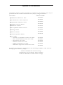
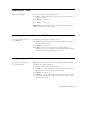
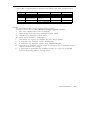
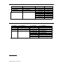
System 25 Documents
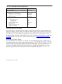
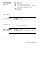
The following System 25 product documents are available for your reference. Copies may be
purchased from the Customer Information Center (CIC) by calling 800-432-6600.
DOCUMENT
ORDER NUMBER
■ Administration
■
An Introduction to AT&T System 25
■ Implementation
■
Manual for R1V2
Manual for R1V2
Installation and Test Manual
■ Maintenance
■ New
555-520-650
555-520-100
555-520-205
555-520-600
■
Planning Manual
■
Reference Manual
■
555-520-021
555-520-105
Manual
Capabilities Manual for R1V2
■ Terminal
555-520-500
555-520-200
Operations Manual
555-520-710
User Guides
—
Switched Loop Attendant Console User Guide
555-520-706
—
Direct Trunk Attendant Console User Guide
555-520-701
—
Data Features User Guide
555-520-704
—
Multiline Terminal User Guide
555-520-703
—
Single-Line Terminal User Guide
555-520-702
—
Multifeature Single-Line Terminal User Guide
555-520-707
To expand your System 25’s communications and networking capabilities, AT&T offers the
following optional software packages:
Advanced Administration Software Package
Communications Access Manager Software Package
STARLAN NETWORK ACCESS Software Package
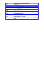
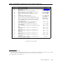
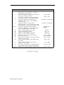
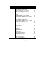
Contents
1
Introduction
Implementation Planning Forms
The System Administrator’s Role
Using this Manual
2
How to Use the System
Logging In to System 25
Correcting Typing Errors
Making Backup Tapes
The System 25 Administration Main Menu
Administration Commands
System Responses
3
2-1
2-2
2-2
2-3
2-4
2-10
Initializing the System
Default Translations
Initialization Sequence
4
1-1
1-1
1-2
3-1
3-3
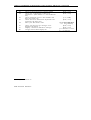
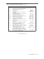
Administering System-Wide Options
Toll Restriction Options
Call Coverage Options
Pooled Modem Options
Time of Day
Date
Call Accounting Options
Miscellaneous System Options
Expert Mode Prompt
Administration Password
Toll Calls Allowed (TCA) Lists
Floating PDCs (FPDCs)
Virtual Facilities
System Speed Dialing
4-1
4-2
4-3
4-4
4-4
4-5
4-6
4-6
4-7
4-7
4-8
4-9
4-10
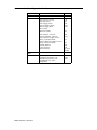
5
Administering Trunks
Assigning a Trunk
Removing a Trunk
Assigning Class of Service to DID Trunks
Assigning Class of Service to All
Other Trunks
6
6-1
6-2
6-3
6-3
6-3
6-3
6-4
6-4
6-4
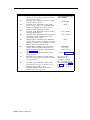
Administering Voice Stations
Adding a Voice Station
Display Support
Removing a Voice Station
Changing a Station Dial Code
Moving a Voice Station
Assigning Class of Service Options
8
5-3
Administering Auxiliary Equipment
External Alerts (Port Type 253)
Paging (Associated with Auxiliary
Trunk Port)
Paging (Associated with CO Trunk Port)
DGC Delay Announcement
Directed Night Service Delay
Announcement
Music-on-Hold
Pooled Modem
Additional Tone Detector
Dictation
7
5-1
5-3
5-3
7-1
7-2
7-2
7-3
7-4
7-4
Administering Data Line and
STARLAN CP Ports
Adding a Data Station
Display Support
Removing a Data Station
Changing a Data Dial Code
Moving a Data Station
Assigning Class-of-Service Options
8-1
8-2
8-2
8-3
8-3
8-4
9
Administering Attendant Equipment
Assign a Switched Loop Attendant Console
Assign a Second Attendant Console
Move an Attendant Console
Change an Attendant PDC
Remove an Attendant Console
Assign a Direct Extension Selector
Console(s)
Display Support
Assign Class-of-Service to an Attendant
Console
Assign Attendant Options (DTAC
and SLAC)
10
9-2
9-2
9-3
9-3
9-3
9-4
9-5
9-5
9-6
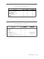
Administering Button Assignments
Assigning Features to Buttons
Default Button Assignments
Button Assignment Tables
Assigning Buttons to Multiline Terminals
and Attendant Consoles
Assigning Attendant-Console-Specific Buttons
Assigning Selector (DXS) Console Buttons
11
Administering Direct Group Calling
(DGC) Groups
12
Administering Automatic Route
Selection (ARS)
ARS Patterns
Area Code Routing Table
Home Area Code Exception List
Other Area Codes Exception List
ARS Digit Translation Tables
10-1
10-1
10-3
10-6
10-10
10-11
12-2
12-6
12-6
12-8
12-8
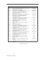
13
Administering Tape Save/Restore
Operations
Using the Digital Tape Unit
Save Your Translations
Verify the Saved Translations
Restore the System Translations from
a Backup Tape
14
15
16
13-4
System Searches
Administering RS232 Parameters
Command Reference
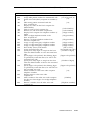
List of Tables
Command Reference
17
13-1
13-2
13-3
Requirements for the SAT
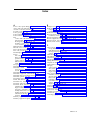
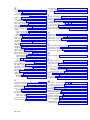
Index
16-1
16-3
Introduction
This manual provides the information you need to administer AT&T System 25 station,
network access, and system features. This includes configuring the system for initial service
(that is, initializing the system) and making day-to-day changes required for efficient
operation. This manual is for Release 1, Version 2 systems only. If you have a Release 1,
Version 1 system, obtain an Administration Manual numbered 555- 500 -500.
This manual assumes that:
■
You have attended the System 25 (Customer or Systems Technician) Training Course.
■
System 25 equipment has been installed and tested.
■
All stations have been tested by the Systems Technician.
■
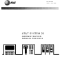
You have available a System Administration Terminal (SAT) with which you will enter
the configuration data. For more information, see Chapter 17, Requirements for the SAT.
Implementation Planning Forms
During implementation planning, you worked with the AT&T Account Team to assign the
features you need for your system and for individual terminals using the forms in the AT&T
System 25 Implementation Manual for R1V2,.
These forms, as explained in the Implementation Manual, provide the information necessary
to enter the initial translations that customize the system. Therefore, the implementation
forms must be completed before you can initialize the system. You should find the forms
collected and filed in the Administration Records Binder (the binder the Implementation Manual
comes in).
This manual also provides instructions for making day-to-day changes after the initial
translations have been entered. It is very important that you record these changes in the
Administration Records Binder. If this is not done, future system administration will
become increasingly difficult.
The System Administrator’s Role
System administration involves initializing the system and administering subsequent terminal
and system changes. The AT&T systems technician is responsible for initializing the system.
At your option, the system administrator or the systems technician may perform subsequent
changes that do not require equipment additions or rearrangements. This manual is designed
to support both the systems technician and the system administrator.
The system administrator is responsible for the following:
■
Training other station users and the attendant.
■
After the system has been initialized, assuring that any additions, changes, or deletions to
system or terminal features are made. Your system administrator may make these
changes or you can contact AT&T to have the technician make the changes.
Introduction 1-1
■
Maintaining system security.
■
Notifying company management (and AT&T) about problems, alarms, and service
complaints.
If you have questions about system hardware or features, you may want to refer to the AT&T
System 25 Reference Manual for more information.
Using this Manual
Before you use the SAT to administer your system, you should have received hands-on
training. You should also read and understand Chapter 2, How to Use the System and
Administering Tape Save/Restore Operations in Chapter 13.
The administration procedures (chapters 4-15) provide detailed step-by-step instructions for
adding trunks and stations and for changing system and station features and options. You
should review the information about default trunk/station numbering in Chapter 3 before you
administer changes. Note that, when adding stations, trunks, or auxiliary equipment
connected to special feature ports, you should first follow the procedure for installing the
equipment, then assign class-of-service information and then make button assignments.
If you are initializing a system, follow the instructions in Chapter 3. It will direct you to
administration procedures in a specific sequence; it is important that you perform the steps in
the indicated order.
Chapter 16 provides quick reference information. The tables in this section are intended to
help those who are thoroughly familiar with system administration locate specific information
without having to refer to the full text in the administration procedure chapters. Unless you
are an experienced system administrator, however, you should follow the administration
procedures.
Conventions Used in this Manual
The following conventions are used in this manual:
■ Commands
and text you should type appear in this font (or style of lettering)
■ System responses, such as prompts and values that appear on the screen, are shown in this font.
■
Names of keys on the SAT keyboard appear in oval boxes. For example: press (Return)
The labels on your keyboard may vary, depending on the kind of terminal you use as an
SAT.
1-2 Introduction
How to Use the System
This chapter describes the way you interact with the system using the System Administration
Terminal (SAT). First, it tells you how to log in to System 25. Then, how to use the Main
Menu to access areas of the system you want to administer. Next, it tells you how to view
and change the way your system operates by entering administration commands. Finally, it
describes the kinds of warning, error, and text messages the system supplies.
Logging In to System 25
System Security
For security reasons, access to the administration capabilities of AT&T System 25 is controlled
by a password. Your password is available from your AT&T Account Team. If you want to
change your password, see the instructions under Administering System-Wide Options.
To prevent an unauthorized person from learning the password, the password characters are
not displayed when they are entered.
If system security is not a problem, because access to the SAT and to this manual are
restricted, you may want to write your password here for convenience:
Entering Your Password
After you turn on the SAT, you see the following prompt:
Enter Password- >
If you do not see this prompt, press (Return)
Enter your password followed by (Return)
Invalid Password Entry
If you enter an invalid password, you see an error message followed by the password
prompt:
That is not the password!
Enter Password- >
Successful Log-in
When you enter the correct password, the terminal displays the Main Menu from which you
can select administration functions.
Leaving an Administration Session
When you complete an administration session, or if you want to interrupt a session at any
point, just turn off the terminal.
How to Use the System 2-1
You can also end an administration session by:
■
Unplugging the cable from the modular jack connecting the terminal to the system.
■
Disconnecting the RS232 connector from the terminal.
■
Hanging up to drop the DTR signal on disconnect if you are connected via a modem.
Correcting Typing Errors
You can correct a typing error by pressing the backspace key. If your keyboard does not
have a backspace key, press (Control) (sometimes abbreviated CTL or CTRL) at the same time
you press h to generate the equivalent of a backspace key.
When you press the backspace key, you see a new line with the last character deleted. For
example, if at the prompt you type four characters and discover that you need only the first
two, you press the backspace key twice. Your terminal responds to the first backspace
character by displaying a line with your last input character removed; it responds to the
second by displaying the line once again with the third input character removed. You can
use this technique (on both video display terminals and printing terminals) to remove
unneeded characters or to replace incorrectly typed characters.
Strange Output
Under unusual circumstances (such as accidentally hitting (Escape) ) your SAT may display
highly abbreviated or unreadable responses. This indicates the SAT is operating in a mode
used for personal computer based administration or is running at the wrong speed. The best
thing to do at this point is to turn off the SAT for five seconds, turn it back on, press (Return)
several times, and log in again. Be sure to check the last items you were administering
before proceeding. For further information, see Requirements for the SAT.
Making Backup Tapes
If your system is equipped with a digital tape unit (DTU), it’s a good idea to make backup
tapes. A backup tape allows you to restore system translations if they are ever lost or
damaged–from an inadvertent cold start, for example. You should make a new backup tape
whenever you make changes to the system. It is strongly recommended that you maintain a
minimum of three backup tapes, updating at least two of them regularly. For more
information, see Administering Tape Save/Restore Operations.
2-2 How to Use the System
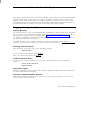
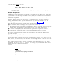
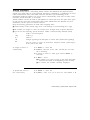
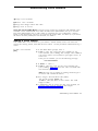
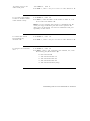
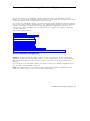
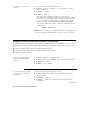
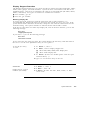
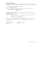
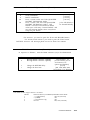
The System 25 Administration Main Menu
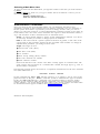
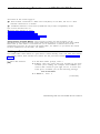
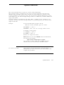
When you log in to the administration terminal, you see the Main Menu. This menu allows
you to enter one of several command areas (Port, PDC, etc.). The Main Menu looks like this
(you may find minor variations on your display):
MAIN MENU
1) PORT
2) PDC
3) reserved
4) SYSTEM
5) FPDC
6) DGC
7) TOLL ALLOWED LIST
8) SEARCH
9) SAVE/RESTORE
10) RS232
11) ARS
12) reserved
Make one selection from menu- >
SCREEN 2-1 Main Menu
When you select an item from the Main Menu, you enter a command area consisting of
action items and data items. You use the action and data items to access specific system
parameters and features. Some command areas require an additional target parameter.
These are discussed in detail in the Command Formats section.
Main Menu Items
The following list describes the features and parameters you can administer through each of
the Main Menu items:
PORT: Allows you to administer station, trunk, data port, or special port parameters by
physical port number. A physical port number is written in the form CSSPP, where C is
the one-digit cabinet number, SS is the two-digit slot number, and PP is the two-digit port
number.
PDC: Allows you to administer station parameters by Personal Dial Code (PDC) or Data
Dial Code (DDC). PDCs and DDCs are similar to extension numbers.
reserved: (Reserved for future expansion.)
SYSTEM: Allows you to administer system-wide parameters.
FPDC: Allows you to administer Floating PDC numbers.
DGC: Allows you to administer Direct Group Calling (DGC) groups.
TOLL ALLOWED LIST: Allows you to administer Toll Calls Allowed Lists.
SEARCH: Allows you to search various groups of system parameters as well as review a
log of system detected errors.
SAVE/RESTORE: Allows you to write translations to, read translations from, and compare
the system translations to translations on the digital tape unit (DTU).
RS232: Allows you to assign Administration, DTU, and SMDR port options.
ARS: Allows you to administer Automatic Route Selection.
reserved: (Reserved for future expansion.)
How to Use the System 2-3
Selecting a Main Menu Item
To select an item from the Main Menu, just type the number of the item you want followed
by (Return)
If you type (Return) by itself or if you type a number that is not between 1 and 12, you see
the following message:
Must be a number from 1-12
Make one selection from menu- >
Administration Commands
Once you select an item from the Main Menu, you can administer the features and
parameters accessible in that command area by entering commands. You use commands to
tell the system what feature or parameter you want to change and the value you want to
change it to. The basic format of a system administration command consists of two items: an
action number, and a data value. Some commands also require a third information number, a
target. The functions of these command items are described below:
Action: An action number defines a specific system administration function. You choose
an action (by number) to examine or change System 25 attributes.
Data: A data value controls a specific System 25 function. In general, a data value is the
current value of the parameter specified by the associated action number. To change an
administration parameter, you change its data value.
Target: The target can be a:
■
Personal Dial Code (PDC)
■
Data Dial Code (DDC)
■
Port number
■
Direct Group Calling (DGC) number
■
Toll Calls Allowed List number
■
RS232 Channel number.
Please note that the words “Action” and “Data” actually appear on command lines. The
word “Target” does not appear on a command line—instead, the target type (e. g., Port, as
shown below) is displayed.
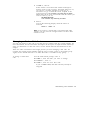
The following example shows the format of a completed command line for the Port command
area (Main Menu item 1):
Port=10401
Action=1
Data=201
In this command line, Port = 10401 tells the system to go to cabinet 1, slot 04, port 01–the
physical location of the port. Action = 1 tells the system to administer the type of terminal.
In this case, Data = 201 indicates a single-line voice terminal without a message waiting
indicator. If you wanted to make this station a single-line voice terminal with a message
waiting indicator, you would change the data value to 202. (Action numbers and data values
for all command areas appear in tables in the Command Reference chapter.)
2-4 How to Use the System
Command Functions
The previous section introduced you to the basic command formats. This section shows you
how to enter or change: an action number, data value, or target value.
Entering Commands
Keep the following considerations about the Return key in mind as you enter commands:
■
As you will see in the section below, to “enter” information means to type the required
numbers or letters and press (Return) The Return key is included in the examples in this
chapter to accustom you to using it. Beginning with the administration procedures in
Chapter 4, however, the Return key is not included. When you are instructed to enter
something in an administration procedure, remember to press (Return) after entering the
required information.
■
The basic, single-letter commands described below are: a for action, d for data, t for
target, c for continue, and m for Main Menu. You can enter these commands at any time
to access prompts and change the current action, data, target, or menu, You do not press
(Return) after typing these commands.
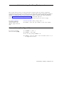
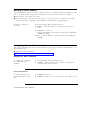
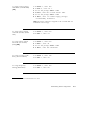
Changing an Action Number
The basic command format shows the current value of a parameter associated with its action
number and the target (if any) that you indicated for that command.
If you want to move to another action number, type A or a on the keyboard. When you
see the Action = prompt, you enter the number of a valid action followed by (Return).
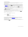
Here is an example of the A command:
You see:
Port = 10604 Action = 1 Data = 304
>
You enter A 7 (Return) and see:
> Action = 7
Port = 10604 Action = 7 Data = 0
>
The action numbers for all command areas are described in detail in the administration
procedure chapters. Some commands require more than one action for their completion.
These commands are described under Action Groups in this chapter.
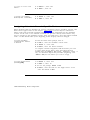
Changing a Data Value
To change the data value associated with an action, first display the current value (as
described above), then type D or d on the keyboard. When you see Data = enter the new
data value followed by (Return).
How to Use the System 2-5
Here is an example of the D command:
You see:
Port = 10604 Action = 7 Data = 0
>
To change, you enter D 5 (Return) and see:
> Data = 5
Port = 10604 Action = 7 Data = 5
>
Changing a Target Value
You can change target values under the following Main Menu items:
■
Port
■
PDC
■
DGC
■
Toll Allowed List
■
RS232
As examples, the next two sections show you how to change a target value under the Port
and PDC Main Menu items. You change target values under the other command areas in the
same way.
Under Port A port number describes the location of a station, trunk, data port, or special
feature port. It is entered in the form CSSPP (described earlier).
If you’ve selected Main Menu item 1 and you want to change the port you’re administering ,
type T or t (target select) on the keyboard. (Remember, you do not have to enter (Return)
with a single-letter command.)
When you see Port = enter the new port number, followed by (Return).
Here is an example of the T (target select) command with Port (Main Menu item 1):
You see:
Port = 20403 Action = 1 Data = 201
>
You enter T 20608 (Return) and see:
> Port = 20608
Action =
Under PDC You can modify stations by selecting the PDC Main Menu item. Instead of
specifying the physical location of the port, as you did in the preceding example, you specify
its PDC.
2-6 How to Use the System
Here is an example of the T (target select) command with PDC (Main Menu item 2):
You see:
PDC = 9876 Action = 1 Data = 201
>
You enter T 8765 (Return) and see:
> PDC = 8765
Action =
Action Groups
Some action numbers are part of groups. These groups are sets of closely related system
parameters that need to be changed as a group. For example, when you assign a voice
terminal, you must also assign a PDC. (See the example at the end of this section. ) Action
groups are marked with [AG] in the administration procedures.
The number of actions may vary from group to group, but no group contains more than five
actions. All action values within a particular group are consecutive. Within a group,
whenever you change a parameter, the system advances you automatically to the next action;
this process continues through the last action in that group.
After modifying a parameter that is part of an action group, you must complete the
modifications to the group by entering data values for the remaining action numbers. This
protects System 25 from acting on partially complete data. When changing data values
associated with these groups of action numbers you automatically advance to the next action
after you change the data value.
You change action numbers with the A command as before.
Note If you change to an action number outside of the group you are currently in, all
the data values entered for that group remain as they were before you began
modifying the group. In other words, if you leave a group (by selecting an action
outside the group) before entering the last data value for that group, all changes for
that group are abandoned.
Here is an example of administering an action group:
You see:
Port = 10408 Action = 1 Data = 0
You enter D 207 (Return) and see:
> Data = 201
Port = 10408 Action = 1 Data = 201
>
Port = 10408 Action = 2 Data = 0
> Data =
Notice in the fourth line of this display how the system automatically brings up the
next member of the group.
How to Use the System 2-7
You enter 6789 (Return) and see:
> Data = 6789
Port = 10408 Action = 2 Data = 6789
>
There are no more members in this action group, so the system does not prompt for
more data values.
Display Support IDs
The Display Support feature lets you enter an ID (or name) for each PDC, DDC, FPDC, DGC
access code, and trunk, creating a database for use during system administration. For
systems with a Switched Loop Attendant Console (SLAC), it is essential that you enter this
information. For systems with a Direct Trunk Attendant Console (DTAC), entering this
information is optional.
In a SLAC system, the Display Support database provides call information to attendants on
the SLAC display. Display IDs also provide a convenient way to search for information
during administration. DTAC system administrators may also find it helpful to use the
Display Support search functions (see Action numbers 40-43 in Chapter 14).
Keep the following parameters in mind when entering Display IDs:
■
The maximum number of Display IDs the system can store is 272.
■
Display IDs can contain 11 characters or less, and must be enclosed in double quotes.
Acceptable characters include any printable ASCII character (including spaces), except the
double quote. Note that only the first 9 characters are shown on the SLAC display.
■
To remove a Display ID, you enter two double quotes, with no space in between.
■
When entering a Display ID name, it is recommended that you use the format
“last name, first name”
Procedures for entering specific Display IDs are included in the applicable administration
procedure chapter.
Lists, Searches, and Port Removal
Lists
Several Main Menu command areas involve administering a group or “list.” These areas are
DGC, FPDC, Toll Allowed List, and ARS. There are also Night Service Trunk lists under the
Port and PDC Main Menu items.
Each of these areas includes a “display” action that shows the members of the list. When
you select this action, the system displays the first member of the list. To see the next
member in the list, type C or c to continue. For example, if you select Main Menu item 5
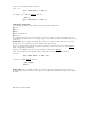
(FPDC) and want to display active FPDCs:
You see:
> Action =
You enter 1 (Return) and see:
> Action = 1
c to continue list, anything else to abort
>
FPDC: Action=1 Data=6666
>
2-8 How to Use the System
You enter C and see:
FPDC: Action = 1 Data = 7777
>
You enter C and see:
FPDC: Action = 1 Data = 8888
>
You enter C and see:
FPDC: Action = 1 Data = 9999
>
You enter C and see:
P16: END OF LIST
FPDC: Action=1 Data=0
>
You may also “abort” the list by typing a, d, or m.
Searches
The Search menu item is similar to the lists described above. However, most types of
searches require at least two steps:
■ Action = 1 Data =
[data value] to identify the type of search you want.
■ Action = 2 Data =
[data value] to narrow the range of the search.
■
A few search areas require a third step, Action = 3 Data = [data value] to further
narrow the range of search—to just translated or untranslated ports, for example.
When you enter the type of search and the required qualifiers, you begin the actual search by
typing C or c , “commence search.”
Removing Ports
When (under Port or PDC on the Main Menu) you try to remove a port from the system,
there are several kinds of associations you may want to investigate before you remove that
port from the system. These associations (for example, the appearance of a trunk on several
station buttons or an external alert associated with a station) are called blocks. System 25
generates warning messages about these blocks so you do not perform an administration
function that goes beyond your intent. For each type of association, you will see a warning
message. To go on with the action, you respond to the system message
c for continue, any other key for abort. When there are no more associations with a station
port you want to remove, you see the warning message,
W18: NO MORE BLOCKS.
The system displays this message to prevent you from accidentally removing a port from the
system.
The next section describes system responses, such as warning messages, in more detail.
How to Use the System 2-9
System Responses
During an administration session, there are occasions when you may enter inappropriate
information at a prompt. While System 25 does not catch all input errors, it does catch many
of them. System 25 has three means of responding to incorrect input:
■
Error messages
■
Print messages
■
Warnings
Error Messages
Error messages are in the general form:
Error nnnn
aaaaa aaaa
[Where nnnn is a number]
[Where aaaaa aaaa is a message]
A second level of help is also available. If you need more information about an error
message in the form above, you can type a question mark, “?,” at the next prompt. You will
see a second message in the this general form:
Error nnnn [Where nnnn is a number]
bbbbb bbbb [Where bbbbb bbbb is an expanded message]
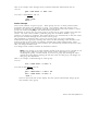
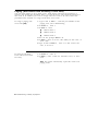
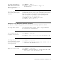
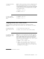
Consider a specific example. You can only change a station PDC to a number that does not
already exist in the dial plan. Say that you attempt to change PDC 1654 to 1653 which is
being used elsewhere:
To change a station PDC
1 At the Main Menu prompt, enter 2 to access the PDC
menu.
2 At PDC = , enter the PDC you want to change, 7654.
3 At Action = , enter 2 to tell the system you want to enter
a new PDC.
4 Type d and at Data = , enter the new dial code, 1653
If you see:
Error 7012
inappropriate request
Data =
that station may already exist.
5 To request additional help on this error message, type ?
You see the second level error message followed by a new
prompt:
Error 7012
PDC already exists
Data =
The system continues to prompt for correct data.
2-10 How to Use the System
Print Messages
This kind of message is straightforward–it conveys information. A print message does not
describe an error condition.
A print message appears at the end of certain search lists. For example, if you enter the
Search option (item 8 from the Main Menu) and search the table of most recent system
errors, you see the following message when you reach the end of that list:
P16: END OF LIST
Warning Messages
A warning message gives you the opportunity to reconsider the administration activity you
are about to perform. One of the more vivid possibilities for serious repercussions would be
your command to cold start the system.
A cold start removes all the current translations in the system, installs default translations,
and cancels all calls in progress on the system. The cold start command, which can be issued
from Main Menu item 9 (Save/Restore), produces serious system disruption. (This command
should be used only by qualified systems technicians.)
If you issue an administration command to force a system cold start, you see the following
warning message:
W23: YOU ARE ABOUT TO FORCE A COLD START
c for continue, any other key for abort
>
At this point, you can still change your mind and back out of the cold start action by entering
any character except “c.”
How to Use the System
2-11
Initializing the System
This section outlines the procedure for administering initial system translations (that is, for
initializing) the system).
To initialize the system, you must know the desired configuration. The System 25
implementation forms contain all the information necessary to initialize the system; they also
form the basis for system Administration Records. These forms should be properly organized
in the Administration Records Binder.
As the system is initialized, it is essential that you write all port assignments on the forms as
the ports are translated. Failure to do this will make future changes and additions very
difficult.
The steps outlined in the Initialization Sequence below should be followed in the sequence
indicated to set up the system. Difficulties may arise if this sequence is not followed.
Default Translations
Two types of cold starts are possible with System 25, which differ in the extent of their
default assignments. A “full default” cold start is usually reserved for an extreme system
disruption, such as might result from a damaged system translation tape or from replacing a
memory board.
The other type of cold start is a “limited default” cold start. It assigns only system defaults
(from menu 4) to the system, leaving port assignments (menu 1) blank. This type of cold
start may be particularly useful during system initialization, if the dial plan you want to
administer is greatly different from the one System 25 assigns in a full-default cold start. The
next two sections describe these cold starts in more detail. For specific cold start procedures,
see Action=20 under Administering Tape Save/Restore Operations.
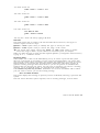
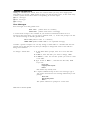
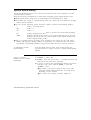
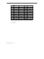
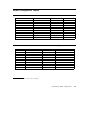
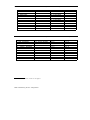
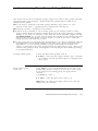
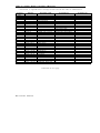
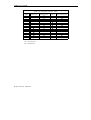
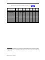
Full-Default Cold Start
With a full-default cold start, System 25 assigns default dial codes and trunk numbers as
shown in Table 3-1. As you attempt to assign dial codes to stations and trunks following the
steps outlined in the next chapter, you may encounter error messages indicating that the
numbers/codes you are trying to assign are already assigned. It may be that the default
numbering plan conflicts with the one you are implementing. If this happens, change the
conflicting default code by first removing the present dial code, then replacing it with the one
you want.
Initializing the System 3-1
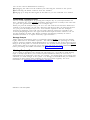
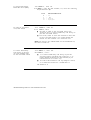
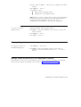
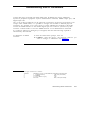
TABLE 3-1 Default Dial
Code Assignments
Port
Default Code
Trunk Numbers (not part of dial plan)
0001-0104
Station Dial Codes:
Multiline voice terminals
Single-line voice terminals
Data terminals
System Dial Codes:
Trunk Access Codes:
Loop start
Ground start
Tie trunks
Attendant Call Park
Night Service
Modem Request Code
(Pooled Modem)
ARS
200-238
300-355
400-599
600-704
100
101
102
800-807
810
820
9
Limited Default Cold Start
If you have many conflicting default codes, you may want to perform a limited default cold
start. This type of cold start does not assign a numbering plan to the system, except for the
800-series numbers and the ARS code listed in Table 3-1. Since the system does not assign
defaults for stations and trunks, it is easier for you to assign numerous new dial codes, since
you don’t have to remove default-assigned dial codes before you can add the new codes.
A limited default cold start does assign most of the system defaults from menu 4, except the
modem request code and CO trunk pool access code. You need to reassign those codes after
a limited default cold start. (See Action=60 and Action= 71 in Administering System-Wide
Options.)
Unassigned Trunk Ports
It is also important to untranslate (or remove) any unassigned trunk ports on System 25. To
untranslated, follow the procedure for removing a trunk. This tells the system that no facility
is assigned to that port. Since outgoing trunk selection of pooled facilities is made in reverse
order of trunk assignment (last assigned is first selected), default assigned trunks that are not
actually connected to incoming facilities will result in the selection of unconnected port
circuits for outgoing calls. System users will receive a reorder tone when trying to access
such ports. The circuit pack will display a red alarm LED and the attendant console will
display a green alarm LED. Then you will have to untranslate the port.
3-2 Initializing the System
Initialization Sequence
Begin with a Cold Start
When you administer the initial translations, it is important that you begin from a known
condition. You can establish a known condition by forcing a cold start (Menu 9, Action=20,
Data=1 or 2). As explained in the previous section, a full default cold start (which takes
about 3 minutes) causes the system to check all slots for valid circuit pack (CP) types and
assign default translations to all ports (except auxiliary trunk ports). A limited default cold
start, which takes about 30 seconds, causes the system to assign system-menu defaults but no
port-specific translations.
During a full default cold start, the SAT lists all circuit packs in the system. When the cold
start is complete, every CP (except the Memory and Auxiliary Trunk) should show a green
LED; in addition, the yellow LED on the Service Circuit should be flashing or steady and the
CPU green LED should be flashing. No red LEDs should be on.
When a limited default cold start is complete, the yellow LED on the Service Circuit should.
be flashing or steady, the CPU green LED should be flashing, and the green Tone Detector
LED should be steady. No red LEDs should be on.
If you cannot bring your system to the state you want, refer to the System 25 Maintenance
Manual before proceeding.
To Initialize the System
The implementation forms provide the information you need to complete the administration
procedures in the following chapters and enter initial translations. When you initialize the
system, you should accept default values for all options and parameters not listed on the
implementation forms. These defaults have been chosen to provide good service for most
customers.
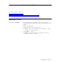
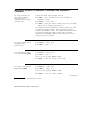
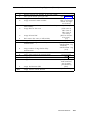
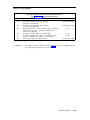
The next table lists the order of administration procedures and implementation forms you
need to initialize the system.
Initializing the System 3-3
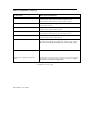
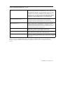
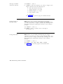
TABLE 3-2 Initialization Sequence
From the information provided
on this form,
Enter these translations:
1 System Options Form
Enter system toll restriction options, pooled modem
options, and other system options following the
procedures in Administering System-Wide Options.
2 Toll Calls Allowed Lists Form
Enter these lists following the procedures in Administering
System-Wide Options
3 Floating Personal Dial Code List
Enter all Floating PDCs following the procedure in
Administering System-Wide Options
4 System Speed Dialing List
Enter System Speed Dialing numbers following the
procedure in Administering System-Wide Options
5 Virtual Facility List
Enter virtual facility codes following the procedure in
Administering System-Wide Options.
6 Trunk forms
Assign all trunk ports and assign each trunk’s class of
service following the procedures in Administering Trunks.
Be sure to record port assignments on the trunk forms.
7 Auxiliary Equipment Options
form
Assign and set up any special feature ports following the
procedures in Administering Auxiliary Equipment. Again,
be sure to record port assignments.
Continued on next page
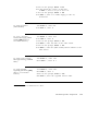
3-4 Initializing the System
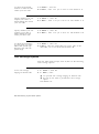
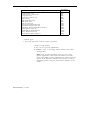
TABLE 3-2 Initialization Sequence (continued)
8 Voice and Data Station Records
form
Assign all station ports (except for attendant consoles),
following the procedures in Administering Voice Stations
and Administering Data Line and STARLAN CP Ports. Do
not enter class-of-service parameters yet. There are some
procedures you cannot complete until all stations are
assigned, such as button assignments. Be sure to record
each station’s port assignment on the individual voice
terminal or data terminal forms as you assign them.
9 Attendant Options and
Attendant Console forms
Assign ports and enter class-of-service, attendant features,
and button feature assignments for the attendant
console(s) following the procedures in Administering
Attendant Equipment and Administering Button Assignments.
10 Terminal forms
Enter class-of-service information for all voice and data
stations (and button assignments for multiline voice
terminals) following the procedures in Administering Voice
Stations, Administering Data Line and STARLAN CP Ports,
and Administering Button Assignments.
11 Direct Group Calling List
Enter DGC groups following the procedure in
Administering Direct Group Calling (DGC) Groups.
12 Automatic Route Selection
Forms
Enter ARS options and patterns following the procedure
in Administering Automatic Route Selection (ARS).
13 Tape Save/Restore
Save the system translations and verify their accuracy
following the procedures in Administering Tape Save/Restore
Operations.
When you have completed these steps, the system is initialized. Be sure to test that the
system is properly initialized following the procedures in the System 25 Installation and Test
Manual.
Initializing the System 3-5
Administering System-Wide Options
This section describes how to set system-wide options which include:
■
Toll Restrictions
■
Call Coverage
■
Pooled Modem Options
■
Time of Day
■
Date
■
Call accounting options which include:
■
—
SMDR
—
Number of digits used for account codes
Miscellaneous system options which include:
—
Maintenance Busy for Ground Start Trunks
—
CO trunk pool access code
—
Number of DID digits used for PDCs
■
Expert mode prompt
■
Administration password
■
Toll Calls Allowed Lists
■
Floating PDCs (FPDCs)
■
Virtual Facilities
■
System Speed Dialing
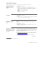
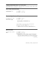
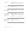
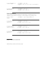
Toll Restriction Options
From the Main menu prompt, enter 4, then set the following
toll restriction options:
To specify your area code
1 At Action = , enter 3 0 .
2 At Data = , enter your area code.
Administering System-Wide Options 4-1
To allow toll restricted
stations to make toll calls
within your area code
Specify whether your CO
requires you to dial “ 1”
before dialing calls outside
your area code
Specify whether your CO
requires you to dial “1”
before dialing toll calls
within your area code
To check toll restrictions
on calls made over interPBX trunks (trunk type
805) that start with one
specific digit
1 At Action = , enter 3 1 .
2 At Data = , enter 1 for yes or 0 for no. The default is 1 .
1 At Action = , enter 32.
2 At Data = , enter 1 for yes or 0 for no. The default is 1.
1 At Action = , enter 33.
2 At Data = , enter 1 for yes or 0 for no. The default is 0.
1 At Action = , enter 34.
2 At Data = , enter the single-digit CO access code of the
other PBX, 1-9 or 0 for none. The default is 9.
Call Coverage Options
From the Main menu prompt, enter 4, then set the following
Call Coverage options:
To set call coverage
ringing on internal calls
1 At
Action = , enter 40.
2 At
Data = , enter:
■
1 to provide call coverage ringing on internal calls.
■
0 if you do not want to provide this call coverage
option.
The default is 1.
4-2 Administering System-Wide Options
To specify the number of
rings before calls are sent
to call coverage or call
following calls return to
their home station
1 At Action = , enter 4 1 .
2 At Data = , enter a number between 0 and 31 for the
number of rings. The default is 2.
Pooled Modem Options
From the Main menu prompt, enter 4 then set the following
Pooled Modem options:
To specify the Modem
Request Code
To set the receiver to
respond to remote loop
To set disconnect on loss
of carrier
To set pins CF and CB as
common
1 At Action = , enter 60.
2 At Data = , enter a number between 1 and 9999. The
default is 820.
1 At Action = , enter 61.
2 At Data = , enter 1 for yes or 0 for no.
The default is 1@.
1 At Action = , enter 62.
2 At Data = , enter 1 for yes or 0 for no.
The default is 1@.
1 At Action = , enter 63.
2 At Data = , enter 1 for yes or 0 for no.
The default is 1@.
@ Strongly recommended this value be used.
Administering System-Wide Options 4-3
To state whether there is
disconnect on received
space
To state whether the
system should send a
space character on
disconnect
1 At Action = , enter 64.
2 At Data = , enter 1 for yes or 0 for no
The default is 1 @ .
1 At Action = , enter 65.
2 At Data = , enter 1 for yes or 0 for no.
The default is 1@.
Time of Day
To set the time of day
1
From the Main menu prompt, enter 4.
2
At Action = , enter 50.
3
At Data = , enter the time of day in the form HHMM
where HH = hour (00 through 23) and MM = minutes (00
through 59).
Date
To set the date
1 From the Main menu prompt, enter 4.
2 At Action = , enter 51.
3 At Data = , enter the date in the form MMDDYY where
MM = month (01 through 12), DD = day (01 through 31),
and YY = year (00 through 99).
@ Strongly recommended this value be used.
4-4 Administering System-Wide Options
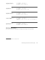
Call Accounting Options
From the Main menu prompt, enter 4, then set the following
call accounting options:
SMDR
Specify whether SMDR
records should be sent to
the SMDR port
To specify the minimum
length (number of
seconds) of outgoing calls
that are reported by
SMDR
1 At Action = , enter 52.
2 At Data = , enter 1 for yes or 0 for no.
The default is 1@.
1 At Action = , enter 53.
2 At Data = , enter a number between 10 and 255. The
default is 40.
Account Codes
To assign the number of
digits used for account
codes
1 At Action = , enter 73.
2 At Data = , enter a number between 1 and 15. The
default is 15.
@ Strongly recommended this value be used.
Administering System-Wide Options 4-5
Miscellaneous System Options
From the Main menu prompt, enter 4, then set the following
system options:
To block maintenance
busy of Ground Start
trunks
To assign the Central
Office trunk pool access
code
1 At Action = , enter 70.
2 At Data = , enter 0 for no or 1 for yes.
The default is 0@.
Note This code cannot be changed after any trunks have been
assigned with this facility access code.
1 At Action = , enter 71.
2 At Data = , enter the CO trunk access code. The default
is 100, 101, or 102, depending on the trunk type.
To set the number of DID
digits used to match
against station PDCs
1 At Action = , enter 72.
2 At Data = , enter a number between 2 and 4.
The default is 3.
Expert Mode Prompt
To change the expert
mode prompt
1 From the Main menu prompt, enter 4 .
2 At Action = , enter 74.
3 At Data = , enter the new prompt (nine or fewer printable
characters). The default is “Command:”.
@ Strongly recommended this value be used.
4-6 Administering System-Wide Options
Administration Password
To change the
administration password
1 From the Main menu prompt, enter 4 .
2 At Action = , enter 75.
3 At Data = , enter the new password (eight or fewer
printable characters, with no spaces). For security, the
display always shows ????????.
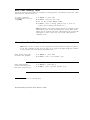
Toll Calls Allowed (TCA) Lists
There are four Toll Calls Allowed Lists. Therefore, you must specify a target value from 1
through 4 to access these lists. The total number of entries must not exceed 64 for all 4 lists
combined.
To access a Toll Calls
Allowed List
1 From the Main menu prompt, enter 7.
2 At the prompt, TOLL ALLW= , enter the number, from 1
through 4, of the list you want to access.
Continue to administer the Toll Calls Allowed List as
described below.
To list members of a TCA
group
To add a code to the list
1 At Action = , enter 1
2 To continue the list, enter c after each code is printed.
1 At Action = , enter 2.
2 At Data = , enter the code number in the form NXX or
NPA-NXX, where:
■
NXX is a 3-digit CO exchange code
■
NPA-NXX is a combination of an area code (NPA) and
a CO code (optionally separated by a hyphen)
You can use the WILDCARD character (•) in the CO
exchange code part (NXX) of these codes. That is, you can
enter NXX as NXX, NX•, N••, or •••.
To specify an entire NPA, enter NPA-•••.
Administering System-Wide Options 4-7
To delete a code from the
list
1 At Action = , enter 3.
2 At Data = , enter the code you want to delete exactly as it
was listed using Action=1.
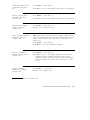
Floating PDCs (FPDCs)
From the Main menu prompt, enter 5; then follow the
procedure below to list, add, or delete an FPDC.
To list FPDCs
1 At Action = , enter 1.
2 To continue the list, enter c after each FPDC is printed.
To add an FPDC
1 At Action = , enter 2.
2 At Data = , enter the FPDC you want to add (1-9999).
To delete an FPDC
1 At Action = , enter 3.
2 At Data = , enter the FPDC you want to delete.
Note When you remove an FPDC, any Display ID for that
FPDC is also removed.
Display Support
To assign or remove an
FPDC Display ID
1 At Action = , enter 4.
2 At Data = , enter the FPDC.
3 Type a and at Action = , enter 5.
4 At Data = , enter the FPDC ID (not more than 11
characters, enclosed in double quotes), or “” to remove
the ID.
4-8 Administering System-Wide Options
Virtual Facilities
A Virtual Facility (VF) is a call-routing facility which is not defined by the physical facility
(trunk) over which calls are routed. Instead, the facility is defined by a combination of access
codes, authorization codes, and coded characters that allow special handling of the
destination telephone number. VFs can be used to automatically route calls via other carrier
networks, private networks, or tie trunks.
Virtual Facilities can also be used in ARS patterns to ensure that users who place these types
of calls use the route (the virtual facility) the system administrator has defined. For more
information, see the System 25 Reference Manual.
Keep the following parameters in mind when assigning VFCs:
■
Virtual Facility Codes (VFCs) range from # 190 through # 199 (including the # sign)
■
The number you assign to a VFC can contain up to 28 digits and/or special characters.
■
You can use the following special characters within a Virtual Facility Number (VFN):
*
sends a 1.5-second pause
##
sends a #
#*
sends a
#3
changes signaling from dial pulse to Touch Tone (end-to-end signaling)
#5
tells the system to insert the destination telephone number (dialed digits)
at this point in the VFN
To assign or remove a
virtual facility
*
1 At Action = , enter 25.
2 At Data = , enter the access code, 190-199 (do not enter
the # character).
3 To assign or remove a VFN, type a and at Action = ,
enter 2 6 .
4 At Data = , enter
To permit dial access to
this virtual facility
■
the number you want to assign to this VFC (allowable
characters are listed at the beginning of this section).
■
0 to remove the number currently displayed
1 At Action = , enter 27.
2 At Data = , enter 1 for yes or 0 for no. The default is 0.
Administering System-Wide Options 4-9
System Speed Dialing
System Speed Dialing allows you to enter a four-character code at any terminal to call the
associated phone number.
Keep the following considerations in mind when assigning System Speed Dialing codes:
■
Speed Dialing Codes range from # 100 through # 189 (including the # sign).
■
The number you assign to a Speed Dialing Code can contain up to 28 characters or digits
and/or special characters.
■
You can use the following special characters within a System Speed Dialing number:
*
sends a 1.5-second pause
##
sends a #
#*
■
sends a
*
#3
changes signaling from dial pulse to Touch Tone (end-to-end signaling)
# 19x
embeds a Virtual Facility Code ( # 190-# 199) as the first part of a Speed
Dialing Code (Note that you cannot embed another Speed Dialing Code
within a Speed Dialing Code.)
There is a limited amount of storage space available in the system for use with speed
dialing and repertory dialing numbers. Consequently, it is important that you remove
any unused speed dialing numbers (using the procedure below) to conserve memory.
To administer System
Speed Dialing
From the Main menu prompt, enter 4; then follow the
procedure below to assign or remove a System Speed Dialing
number.
Enter or remove a
number from the Speed
Dialing list
1 At Action = , enter 25.
2 At Data = , enter the access code — a number between 100
and 189 (do not enter the # character).
3 To assign or remove the speed dialing number associated
with this code, enter a and at Action = , enter 2 6 .
At Data = , enter:
■
the number you want to assign to this access code
(allowable Speed Dialing characters are listed at the
beginning of this section).
■
0 to remove the number currently displayed
4-10 Administering System-Wide Options
Administering Trunks
This section shows you how to:
■
Assign and remove trunks
■
Assign class-of-service parameters for various types of trunks
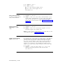
Assigning a Trunk
To assign a trunk [AG]
From the Main menu prompt, enter 1, then follow the
procedures below to define the trunk type and assign a trunk
number.
Define the trunk type:
1 From the Main menu prompt, enter 1.
2 At Port = , enter the carrier/slot/port (CSSPP) to which
you want to assign the trunk.
3 At Action = , enter 1.
4 At Data = , enter the trunk type number. Select the
number from the next table.
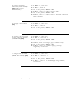
Administering Trunks 5-1
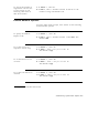
TABLE 5-1 Trunk-Type Codes
If the Trunk Type is:
Ground Start, CO
Ground Start, WATS, FX
Loop Start, CO
Loop Start, WATS, FX
PBX/Centrex
DID Immediate Dial
DID Wink Start
Auto-in/Auto-out
Auto-in/Immediate Dial-out
Immediate Dial-in/Auto-out
Immediate Dial-in/Immediate Dial-out
Wink Dial-in/Auto-out
Wink Dial-in/Wink Dial-out
Delay Dial-in/Auto-out
Delay Dial-in/Delay Dial-out
You Enter:
701*
702
801*
802
805†
901
902*
1001
1002
1003
1004
1005
1006*
1007
1008
* Default Type
† You must select this code for Centrex operation.
Assign a trunk number:
1 You see the prompt, A c t i o n = 2 .
2 At Data= , enter a four-digit trunk number from 0001
through 9999.
Note Trunk numbers beginning with 9 (”9xxx”) have
special significance when used with Dial-in tie trunks
(types 1003-1008). System administrators should read the
section in the Reference Manual called Tandem Trunking
thoroughly before using any 9xxx-format numbers for tie
trunks.
5-2 Administering
Trunks
Removing a Trunk
To remove a trunk
1 From the Main menu prompt, enter 1.
2 At Port = , enter the physical port you want to remove in
the form CSSPP.
3 At Action = , enter 1.
4 At Data = , enter 0.
Note When you remove a trunk, any Display ID associated
with the trunk is also removed.
Assigning Class of Service to DID Trunks
To assign class-of-service
to a DID trunk
1 From the Main menu prompt, enter 1.
2 At Port = , enter the physical port to which you want to
assign class of service.
3 At Action = , enter 3.
4 At Data = , enter the class-of-service code which is a
number (1, 2, 3, or 4) equal to the number of digits the CO
sends over this trunk. The default is 3.
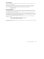
Assigning Class of Service to All Other Trunks
To assign class of service
to all other trunks
Note This section assumes that your trunks and their trunk
numbers have been assigned.
1 From the Main menu prompt, enter 1.
2 At Port = , enter the physical port to which you want to
assign class of service in the form CSSPP.
3 At Action = , enter 3.
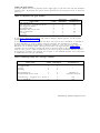
4 At Data = , enter the trunk class of service code from the
next table. The default is 8. For dial-in tie trunks, only
codes 0-7 are valid.
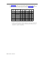
Administering Trunks 5-3
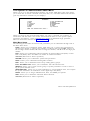
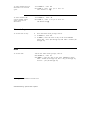
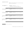
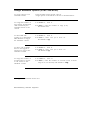
TABLE 5-2 Trunk Class of Service (for all trunks except DID)
COS
CODE
0
1
2
3
4
5
6
7
8
9
NIGHT
SERVICE
●
●
OUTWARD
SIGNALING
TT
TT
TT
TT
DP
DP
DP
DP
TT
TT
10
11
12
13
14
15
●
●
●
●
●
●
TT
TT
DP
DP
DP
DP
TT = Touch-Tone
DP = Dial-Pulse
5-4 Administering
Trunks
IN
ONLY
SHORT
DISCONNECT
●
●
●
●
●
●
●
●
●
●
●
●
●
●
●
●
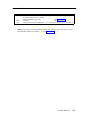
Class-of-Service Options
Follow the procedures below to assign class-of-service options to this trunk.
Pooled Facility Access
Group: Is this trunk in a
pooled facility access
group?
Dial Access
1 At Action = , enter 4.
2 At Data = , if the trunk is in a pooled facility access
group, enter the facility access code (FAC). Enter 0 if the
trunk is not in any group. The defaults are as follows:
■
100 for Loop Start trunks
■
101 for Ground Start trunks
■
102 for Tie trunks
1 At Action = , enter 5.
2 At Data = , enter 1 if you want to allow dial access, enter
0 if you do not. The default is 1@.
DGC Group: To assign
this trunk to a DGC
group
Note This item is not administerable for trunk types 10031008.
1 At Action = , enter 6.
2 At Data = , enter the DGC group number (l-32, or 0 for
none). The default is 0.
Night Service: To choose
either Directed or TrunkAnswer-from-Any-Station
(TAAS) Night Service for
this trunk
To receive either form of night service, this trunk’s class of
service must include night service (that is, for Action=3, Data
must be between 8 and 15). Also, a NIGHT button must be
assigned to the attendant console.
■
For Directed Night Service, at least one station must be
assigned to receive night service calls from this trunk (see
Administering Voice Stations).
■
For TAAS Night Service, an external alert must be
assigned for night service use.
(continued)
@ Strongly recommended this value be used
Administering Trunks 5-5
1 At
Action = , enter 7 .
2 At
Data = , enter:
■
1 to select Directed Night Service
■
0 to select TAAS Night Service.
The default is 1.
Delay Announcement:
To assign a Night Service
delay announcement
Type of Incoming
Signaling (tie trunks
only)
1 At Action = , enter 8.
2 At Data = , enter 1 for first delay announcement, 2 for
second delay announcement, or 0 for none. The default
is 0. (See the procedure for assigning Directed Night
Service Delay Announcement under Administering Auxiliary
Equipment.)
1 At Action = , enter 9.
2 At Data = , enter 1 for Touch-Tone signals, or 0 for
Dial-Pulse signals. The default is 0.
Note To connect this tie trunk directly to another PBX, see the
“Port Options” table in Command Reference.
Pooled Trunk Hunting
Order: {Read Only}
For outgoing calls, each trunk in a trunk group is selected in a
certain sequence. The value returned from this action/data
pair tells you what position in the list this trunk occupies
(e.g., first, second, third...). The order in which trunks are
used is the reverse of the order in which the trunks were
assigned. For example, if you installed four trunks in the
order 1, 2, 3, and 4, those trunks would be used in the order
4, 3, 2, and 1.
1 At Action = , enter 10. Data shown (1, 2, etc.) is the
order in which that particular trunk will be used
(1st, 2nd, etc.).
5-6 Administering
Trunks
Assigning Trunk Options to a SLAC System
The following options apply only to systems using the Switched Loop Attendant Console
(SLAC), and are not administerable for DID trunks:
To set the priority of a
trunk to ring in the
attendant-console queue
1 At Action = , enter 11.
2 At Data = , enter a trunk priority number, 0-7:
■
1 - highest priority
■
7 - lowest priority
■
0 - the trunk won’t ring in the queue
The default is 0.
Specify which attendant
should receive calls from
this trunk
1 At Action = , enter 12.
2 At Data = , enter the attendant position number, 0-2:
■
1 - first attendant
■
2 - second attendant
■
0 - either attendant
The default is 0.
Display Support
To assign or remove a
trunk Display ID
Note This feature is not administerable for DID trunks.
1 At Action = , enter 90.
2 At Data = , enter the Display ID (not more than 11
characters, enclosed in double quotes), or “” to remove
the ID.
Administering Trunks 5-7
Administering Auxiliary Equipment
This section discusses how to assign and remove AT&T System 25 auxiliary equipment
associated with special ports. It assumes that you know what special equipment is required
and that you have read the System 25 Implementation Manual for R1V2 and/or the Reference
Manual to understand which circuit boards you require to connect this special equipment.
See the “Special Feature Port Type Codes” table in Command Reference.
For all procedures in this section, you must first specify the port you want to assign.
To assign or remove
auxiliary equipment
options listed in this
chapter, begin with this
step
1 From the Main menu prompt, enter 1.
2 At Port = , enter the port number in the form CSSPP.
External Alerts (Port Type 253)
To assign an external
alert for a station [AG]
1 At Action = , enter 1.
2 At Data = , enter 253.
3 You see the prompt: Action = 2.
4 At Data = , enter the PDC of the associated station, or 0
for Night Service Alert.
Administering Auxiliary Equipment 6-1
Paging (Associated with Auxiliary Trunk Port)
You can assign Paging to up to three zones. Each paging zone must be assigned to a
separate port. Follow the procedure below to assign an access code and dial restriction to
each zone. If, in addition, you want to assign one access code to all zones, follow the
procedure below entitled “To assign an All-Zone access code.”
To assign a paging zone
access code [AG]
1 Type t and at Port = , enter the port number for the
paging zone you’re administering
2 At Action = , enter 1.
3 At Data = , enter
■
1301 for Zone 1
■
1302 for Zone 2
■
1303 for Zone 3
4 You see the prompt Action = 2.
5 At Data = , enter an access code (PDC) for this zone, or
0 for none.
6 Type a and at Action = , enter 1 to dial restrict the
zone, or 0 not to.
To assign an All-Zone
access code (if more than
one zone)
1 At Action = , enter 3.
2 At Data = , enter a PDC for All-Zone access, or 0 for
none.
Note The system automatically copies this value to all
paging zones.
6-2 Administering Auxiliary Equipment
Paging (Associated with CO Trunk Port)
If the paging system is connected to a loop or ground start trunk port, simply assign a trunk
facility access code for the port(s) so connected.
DGC Delay Announcement
To assign DGC Delay
Announcement
1 At Action = , enter 1.
2 At Data = , enter 255.
Directed Night Service Delay Announcement
To assign Directed Night
Service Delay
Announcement [AG]
1 At Action = , enter 1.
2 At Data = , enter
■
251 (Delay Announcement #1)
■
252 (Delay Announcement #2)
Assign number of rings before delay announcement
1 You see the prompt: Action = 2.
2 At Data = , enter the number of rings before an
unanswered call receives delay announcement (1-15).
Music-on-Hold
To assign Music-on-Hold
[AG]
1 At Action = , enter 1.
2 At Data = , enter 2 5 4 .
3 Special Hold: A caller is placed on Special Hold when a
multiline set user presses either Transfer or Conference.
You need to indicate whether or not callers will hear music
during the short interval when they are on Special Hold.
(continued)
Administering Auxiliary Equipment 6-3
You see Action = 2. At Data = , enter:
■
0 - if you do not want Music on Special Hold
■
1 - if you want Music on Special Hold
Pooled Modem
To assign a Pooled
Modem circuit pack
Note See the procedure for setting pooled modem options
under Administering System-Wide Options.
1 At Action = , enter 1.
2 At Data = , enter 1 9 0 1 .
Additional Tone Detector
To assign an Additional
Tone Detector circuit pack
1 At Action = , enter 1.
2 At Data = , enter 2 1 0 1 .
Dictation
To assign Dictation [AG]
1 At Action = , enter 1.
2 At Data = , enter
■
2201 if Auxiliary Trunk interface
■
201 if Station Port interface
Assign the access code
1 You see the prompt: Action = 2.
2 At Data = , enter the PDC.
6-4 Administering Auxiliary Equipment
Administering Voice Stations
■
Assign voice terminals
■
Remove voice terminals
■
Assign and change station dial codes
■
Assign class of service
Using the Port and PDC Menus: Class-of-service options for single-line and multiline voice
terminals can be administered from either the PDC menu (Main Menu item 2) or from the
Port menu (Main Menu item 1). This makes it convenient for you to administer a station
based on the information you have. If you know the station PDC, use Menu 2; if you know
the station location (CSSPP) but not the PDC, use Menu 1.
Adding a Voice Station
You cannot add a voice terminal to a port where a station already exists. You must first
remove the existing station, then add the new station. See the procedure entitled Removing a
Station.
To add a voice terminal
[AG]
1 At the Main Menu prompt, enter 1.
2 At Port = , enter the carrier/slot/port (CSSPP) for the
voice terminal you’re adding. For example, enter 10608 if
you want to add a voice terminal to port eight, slot six, in
carrier one.
If the port is available, you see the following message:
Port not translated
3 At Action = , enter 1.
4 At Data = , enter the code for the voice terminal type
you’re adding. Table 7-1 shows the code associated with
each terminal type.
Note The only way to change an existing terminal type is
to remove and reinstall the station.
5 Next, assign a Personal Dial Code (PDC):
You see the prompt, Action = 2.
At Data = , enter the PDC for this station. The valid
range is 1-9999.
6 To administer class of service for this voice terminal, see
Assigning Class of Service Options in this chapter.
Administering Voice Stations 7-1
TABLE 7-1 Voice Terminal Type Codes
Terminal Type:
Single-line without message waiting indicator
Single-line with message waiting indicator
5-Button MERLIN CS Voice Terminal, Z7302H01
MERLIN CS Hands-Free-Answer Voice Terminal, Z7309H01
10-Button MERLIN CS Voice Terminal, Z7303H01
MERLIN CS Built-in-Speakerphone Voice Terminal, Z7305H03
34-Button MERLIN CS Voice Terminal, Z7305H01
34-Button Deluxe MERLIN CS Voice Terminal, Z7305H02 (non-attendant)
MERLIN CS Built-in-Speakerphone Voice Terminal with 16-Character Display,
Z7305H04C (non-attendant)
Direct Trunk Attendant Console (34-Button Deluxe MERLIN CS
Voice Terminal, Z7305H02)
Switched Loop Attendant Console (MERLIN CS Built-in-Speakerphone
Voice Terminal with 16-Character Display, Z7305H04C)
MET Voice Terminal
Code:
201
202
302
303
304
305
306
307
308
309
310
401
Display Support
To assign or remove a
PDC Display ID
1 At Action = , enter 9 0 .
2 At Data = , enter the Display ID (not more than 11
characters, enclosed in double quotes), or “” to remove
the ID.
Removing a Voice Station
To remove a voice
terminal
Note When you remove a station, any Display ID associated
with that PDC will also be removed.
1 From the Main Menu prompt, enter 1.
2 At Port = , enter the CSSPP for the station you’re
removing.
3 At Action = , enter 1 .
(continued)
7-2 Administering Voice Stations
4
At Data = , enter 0 .
If this station is associated with another station(s) for
features such as Call Coverage, Automatic Intercom, etc.,
you will see a warning message for each type of
association. To go on with the action, respond to the
system message, c for continue, any other key for abort.
When there are no more associations with the station you
want to remove, you see:
NO MORE BLOCKS
c for continue, any other key for abort
5
Enter c.
You see the following display when the station is
removed:
Action = 1 Data = 0
Note If you remove a station that is associated with other
stations, you may need to reassign features on those other
stations as well.
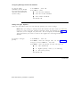
Changing a Station Dial Code
You can only change a dial code to one that does not conflict with any existing number. For
more information, see the “Dial Plan” description in the System 25 Implementation Manual for
R1V2. To determine if a dial code exists, use the Search function described later in this
chapter.
There are other circumstances that might prevent you from changing a dial code. For
example, the existing station number might be part of a DGC group or call pickup group.
Again, use the Search function to see if the dial code is a member of any group.
To change a station dial
code
1 At the Main Menu prompt, enter 2.
2 At PDC = , enter the PDC you want to change.
3 At Action = , enter 2.
4 At Data = , enter the new dial code.
If you see Error 7012, that dial code may already be
assigned.
Administering Voice Stations 7-3
Moving a Voice Station
Use this procedure when you want to move a station – its features, button assignments, and
PDC — to another port. Keep these considerations in mind when you move a station:
■
The moved-to port must be vacant.
■
The terminal types must be the same; that is, you can only move a station to the same
physical type (e.g., multiline voice terminal to multiline voice terminal port).
To move a station to a
new port
1 From the Main Menu prompt, enter 2.
2 At PDC = , enter the PDC of the station you want to
move.
3 At Action = , enter 0.
The system displays the station’s present port assignment
at Data = C S S P P
4 Type d, and at Data = , enter the new port assignment
(CSSPP).
Assigning Class of Service Options
This section describes the class of service options– the calling restrictions and features– you
can administer for:
■
Single-line voice terminals
■
Multiline voice terminals, including attendant consoles
Single-Line Voice Stations
To assign class of service
to a single-line voice
terminal
1 From the Main Menu prompt, enter 2.
2 At PDC = , enter the PDC of the station to which you
want to assign class of service.
Calling Restrictions
To restrict dial access to
the Central Office trunk
pool
7-4 Administering Voice Stations
1 At Action = , enter 3.
2 At Data = , enter 1 for yes or 0 for no. The default is 0 .
To restrict dial access to
all other trunk pools
To restrict this station
from making any
outward calls
To assign a toll restriction
class
1 At Action = , enter 4.
2 At Data = , enter 1 for yes or 0 for no. The default is 0 .
1 At Action = , enter 13.
2 At Data = , enter 1 for yes or 0 for no. The default is 0 .
1 At Action = , enter 14.
2 At Data = , enter the toll class number, 0-4, from the
following list (the default is 0):
0 - Not Toll Restricted
1 - Toll call allowed lists 1-4
2 - Toll call allowed lists 2-4
3 - Toll call allowed lists 3-4
4 - Toll call allowed list 4 (only)
To assign an ARS Facility
Restriction Level (FRL)
1 At Action = , enter 15.
2 At Data = , enter the FRL number, 0-3 , from the
following list (the default is 3):
Allowed FRL Pools
Level
0
1
2
3
-
0
0,1
0,1,2
0,1,2,3
Features
Extended/Off-Premises
Station: To make this
voice terminal an
extended station
1 At Action = , enter 10.
2 At Data = , enter 1 or 0, based on physical connection
information.
Administering Voice Stations 7-5
Station Hunting: To
administer this station to
hunt to another station if
busy
Group Call Coverage: To
specify which receiver
group will cover this
station’s calls
1 At
Action = , enter 12.
2 At Data = , enter the PDC of the station to hunt to next,
or 0 for none. The default is 0.
1 At Action = , enter 7.
2 At Data = , specify which “receiver” group will answer
this station’s calls. Enter:
■
a call coverage group number, 1-32
■
a DGC call coverage group number, 101-132. This
number actually corresponds to a DGC group number
1-32 (the “1“ in the hundreds’ place indicates DGC
coverage instead of standard call coverage).
■
0 for none.
The default is 1.
Call Pickup: To assign
this station to a call
pickup group
Personal Speed Dialing:
To enable personal speed
dialing at this station
Night Service: To display
the number of any trunks
assigned to this station
for Night Service
7-6 Administering Voice Stations
1 At Action = , enter 11.
2 At Data = , enter the group number, 1 through 16, or 0
for none. The default is 0.
1 At Action = , enter 1 6 .
2 At Data = , enter 1 for yes or 0 for no. The default is 1.
1 At Action = , enter 5 1 .
2 To continue the list, enter C after each trunk number is
printed.
To assign a trunk to this
station for Night Service
1 At Action = , enter 52.
2 At Data = , enter a four-digit trunk number.
Note Any given trunk can have no more than four Night
Service coverage stations assigned to it.
To delete a trunk from
this station’s Night
Service list
1 At Action = , enter 53.
2 At Data = , enter a four-digit trunk number.
Multiline Voice Stations
To assign class of service
to a multiline voice
station (including an
attendant console)
1 From the Main Menu prompt, enter 2.
2 At PDC = , enter the PDC of the multiline voice station to
which you want to assign class of service.
Calling Restrictions
To restrict dial access to
the Central Office trunk
pool
To restrict dial access to
all other trunk pools
To restrict this station
from making any
outward calls
1 At Action = , enter 3.
2 At Data = , enter 1 for yes or 0 for no. The default is 0.
1 At Action = , enter 4.
2 At Data = , enter 1 for yes or 0 for no. The default is 0 .
1 At Action = , enter 1 3 .
2 At Data = , enter 1 for yes or 0 for no. The default is 0 .
Administering Voice Stations 7-7
To assign a toll restriction
class
1 At Action = , enter 14.
2 At Data = , enter a toll class number, 0-4, from the
following list (the default is 0):
0 - Not toll restricted
1 - Toll call allowed lists 1-4
2 - Toll call allowed lists 2-4
3 - Toll call allowed lists 3-4
4 - Toll call allowed list 4 (only)
To assign an ARS Facility
Restriction Level (FRL)
1 At Action = , enter 15.
2 At Data = , enter the FRL number, 0-3, from the following
list (the default is 3):
Level
0
1
2
3
Allowed FRL Pools
-
0
0,1
0,1,2
0,1,2,3
Features
Line Preference: To
assign ringing line
preference
To assign prime line
preference
1 At Action = , enter 5. †
2 At Data = , enter 1 for yes or 0 for no.
The default is 1@.
1 At Action = , enter 6.
2 At Data = , enter the button on which this line appears
(the preferred button number), or enter 0 for no line
preference. The default is 7. (See the “Multiline Set
Button Defaults” table under Administering Button
Assignments).
† This is a Read-Only feature for the SLAC.
@ Strongly recommended this value be used.
7-8 Admnistering Voice Stations
Group Call Coverage: To
specify which receiver
group will cover this
station’s calls
1 At
Action = , enter 7. ‡
2 At
Data = , enter
■
a call coverage group number, 1-32
■
a DGC coverage group number, 101-132. This number
actually corresponds to the DGC group number 1-32
(the “1” in the hundreds’ place indicates DGC
coverage instead of standard call coverage).
■
0 for none.
The default is 1.
To assign Call Coverage
Ring on No Answer to a
station that has call
coverage
To assign Call Coverage
Ring on Busy to a station
that has call coverage
Call Pickup: To assign
this station to a call
pickup group
Personal Speed Dialing:
To enable Personal Speed
Dialing at this station
1 At Action = , enter 8. ‡
2 At Data = , enter 1 for yes or 0 for no.
The default is 1@.
1 At Action = , e n t e r 9. ‡
2 At Data = , enter 1 for yes or 0 for no.
The default is 1@.
1 At Action = , enter 11.
2 At Data = , enter the Call Pickup group number, 1-16, or
0 for none. The default is 0.
1 At Action = , enter 1 6 .
2 At Data = , enter 1 for yes or 0 for no. The default is 0 .
‡ This feature is not administrable for the SLAC.
@ Strongly recommended this value be used.
Administering Voice Stations 7-9
Night Service: To display
the number of any trunks
assigned to this station
for Night Service
To assign a trunk to this
station for Night Service
1 At Action = , enter 5 1 .
2 To continue the list, enter C after each trunk number is
printed.
Note Any given trunk can have no more than four Night
Service coverage stations assigned to it.
1 At Action = , enter 52.
2 At Data = , enter a four-digit trunk number.
To delete a trunk from
this station’s Night
Service list
To display attendant
position number (Read
Only)
7-10 Administering Voice Stations
1 At Action = , enter 5 3 .
2 At Data = , enter a four-digit trunk number.
1 At Action = , enter 6 0 .
2 You see either:
■
Data = 1 for the first attendant
■
Data = 2 for the second attendant
Administering Data Line and STARLAN CP Ports
Procedures in this section apply to:
■
A data terminal connected to a Data Line Card (DLC) via an ADU, but not to a data
terminal connected via a modem
■
A STARLAN Interface Circuit Pack (STARLAN CP) in DLC-compatibility mode.
This section describes how to:
■
Assign data stations to ports
■
Remove data stations from ports
■
Assign and change Data Dial Codes (DDCs)
■
Assign class-of-service to data ports
Using the Port and PDC Menus: Class-of-service options for data terminals can be
administered from either the PDC menu (Main Menu item 2) or from the Port menu (Main
Menu item 1). This makes it convenient for you to administer a station based on the
information you have. If you know the station DDC, use Menu 2; if you know the station
location (CSSPP) but not the DDC, use Menu 1.
Adding a Data Station
You cannot add a data station to a port where a station already exists. You must first remove
the existing station, then add the new station. See the procedure entitled Removing a Data
Station.
To add a data terminal
[AG]
1 At the Main Menu prompt, enter 1.
2 At Port = , enter the carrier/slot/port (CSSPP) for the data
terminal you’re adding. For example, enter 10608 if you
want to add a station to port eight, slot six, in carrier one.
If the port is available, you see the following message:
Port not translated
3 At Action = , enter 1.
(continued)
Administering Data Line and STARLAN CP Ports 8-1
4 At Data = , enter the code for the data terminal you’re
adding:
■
1801 for a DLC (ZTN126 or TN726)
■
1802 for a STARLAN CP (ZTN84).
Note The only way to change an existing terminal type is
to remove and reinstall the station.
5 Next, assign a Data Dial Code (DDC):
You see the prompt, Action = 2.
At Data = , enter the DDC for this station. The valid
range is 1-9999.
6 To administer class of service for this station, see Assigning
Class of Service Options in this chapter.
Display Support
To assign or remove a
DDC Display ID
1 At Action = , enter 9 0 .
2 At Data = , enter the Display ID (not more than 11
characters, enclosed in double quotes), or “” to remove
the ID.
Removing a Data Station
To remove a data
terminal
Note When you remove a station, any Display ID associated
with that DDC will also be removed.
1 From the Main Menu prompt, enter 1.
2 At Port = , enter the CSSPP for the station you’re
removing.
3 At Action = , enter 1.
4 At Data = , enter 0.
If this station is associated with another station(s) for a
feature such as Third-Party Call Set-Up, you will see a
warning message for each type of association. To go on
with the action, respond to the system message, c for
continue, any other key for abort. When there are no more
associations with the station you want to remove, you see:
(continued)
8-2 Administering Data Line and STARLAN CP Ports
NO MORE BLOCKS
c for continue, any other key for abort
5 Enter c.
You see the following display when the station is
removed:
Action = 1 Data = 0
Note If you remove a station that is associated with other
stations, you may need to reassign features on those other
stations as well.
Changing a Data Dial Code
You can only change a dial code to one that does not conflict with any existing number. For
more information; see the “Dial Plan” description in the System 25 Implementation Manual for
R1V2. To determine if a dial code exists, use the Search function described later in this
chapter.
There are other circumstances that might prevent you from changing a dial code. For
example, the existing station number might be part of a DGC group or call pickup group.
Again, use the Search function to see if the dial code is a member of any group.
To change a data dial
code
1 At the Main Menu prompt, enter 2.
2 At PDC = , enter the DDC you want to change.
3 At Action = , enter 2 .
4 At Data = , enter the new dial code.
If you see Error 7012, that DDC may already be assigned.
Moving a Data Station
Use this procedure when you want to move a station to another port. Keep these
considerations in mind when you move a station:
■
The moved-to port must be vacant.
■
The terminal types must be the same; that is, you can only move a station to the same
physical type (e.g. data terminal to data terminal port).
(continued)
Administering Data Line and STARLAN CP Ports 8-3
To move a data station to
a new port
1 From the Main Menu prompt, enter 2.
2 At PDC = , enter the DDC of the station you want to
move.
3 At Action = , enter 0.
The system displays the station’s present port assignment
at Data = C S S P P
4 Type d, and at Data = , enter the new port assignment
(CSSPP).
Assigning Class-of-Service Options
This section describes the class-of-service options — the calling restrictions and features — you
can administer for data stations.
When assigning class-of-service options to a STARLAN CP, data port type code 1802, the
default values are relevant for the first installed port on the board. Unless otherwise noted,
values assigned to these action items on any of the four ports will be copied to all four ports
on the STARLAN CP. Therefore, default values listed below may not apply to a STARLAN
CP port, if you have previously changed that value for any port on the board.
To assign class of service
to a data terminal
1 From the Main Menu prompt, enter 2.
2 At PDC = , enter the DDC of the terminal to which you
want to assign class of service.
Note If you are administering a STARLAN CP, the DDC you
assign to the first port will not be copied to the other ports on
the board. You will need to administer each port separately
for this action.
Assign Calling Restrictions
To restrict access to
Central Office trunk pool
1 At Action = , enter 3.
2 At Data = , enter 1 for yes or 0 for no. The default is 0 .
8-4 Administering Data Line and STARLAN CP Ports
To restrict access to all
other trunk pools
To set calls to this station
to hunt to another station
if this station is busy
1 At Action = , enter 4.
2 At Data = , enter 1 for yes or 0 for no. The default is 0 .
1 At Action = , enter 12.
2 At Data = , enter the DDC of the station to hunt to, or 0
for no hunt. The default is 0.
Note If you are assigning this option to a STARLAN CP, the
value you assign to the first port will not be copied to the
other ports on the board. You need to administer each port
separately for this action.
To restrict this station
from making any
outward calls
To assign a toll restriction
class
1 At Action = , enter 1 3 .
2 At Data = , enter 1 for yes or 0 for no. The default is 0 .
1 At Action = , enter 14.
2 At Data = , enter a toll restriction class number, 0-4, from
the following list (the default is 0):
0 - Not toll restricted
1 - Toll call allowed lists 1-4
2 - Toll call allowed lists 2-4
3 - Toll call allowed lists 3-4
4 - Toll call allowed list 4 (only)
Administering Data Line and STARLAN CP Ports 8-5
To assign ARS Facility
Restriction Level (FRL)
1 At Action = , enter 15.
2 At Data = , enter the FRL number, 0-3, from the following
list (the default is 3):
Level
0
1
2
3
To enter an associated
voice/data station
Allowed FRL Pools
- 0
0,1
- 0,1,2
- 0,1,2,3
1 At
Action = , enter 2 1 .
2 At
Data = , enter:
■
the PDC or DDC of the associated station. See
Action=22 next to restrict Third-Party Call Set-Up to
just this associated station.
■
0 for none; either to allow this terminal to dial calls
for any voice/data station, or to totally disable the
feature for this terminal. See Action=22 next.
Note This action is not administrable for the STARLAN CP;
the value is fixed at 0.
To restrict Third-Party
Call Set-Up so the user
can only establish calls
for the associated station
1 At Action = , enter 2 2 .
2 At Data = , e n t e r :
■
1 to restrict Third-Party Call Set-Up to just the
associated station specified with Action=21, or to
totally disable the feature for this terminal (if you
entered Data=0 for Action= 21).
■
0 to allow this terminal to call any endpoint station,
or to enable this feature for a STARLAN CP.
The default is 1.
8-6 Administering Data Line and STARLAN CP Ports
Set Baud Rate and Parity
Note For each data terminal, indicate all permissible operating
speeds and any required parity.
To auto-adjust baud rate
on call origination
1 At Action = , enter 61. ‡
2 At Data = , enter 1 for yes or 0 for no.
The default is 1 for DLC and 0 for STARLAN CP.
Can this terminal operate
at a low data rate?
Can this terminal operate
at a baud rate of 300 bps?
Can this terminal operate
at a baud rate of 1200
bps?
Can this terminal operate
at a baud rate of 2400
bps?
1 At Action = , enter 62. ‡
2 At Data = , enter 1 for yes or 0 for no. The default is 0 .
1 At Action = , enter 63. ‡
2 At Data = , enter 1 for yes or 0 for no. The default is 1 .
1 At Action = , enter 64. ‡
2 At Data = , enter 1 for yes or 0 for no. The default is 1 .
1 At Action = , enter 65. ‡
2 At Data = , enter 1 for yes or 0 for no. The default is 1 .
‡ This is a Read-Only feature for the STARLAN CP
Administering Data Line and STARLAN CP Ports 8-7
Can this terminal operate
at a baud rate of 4800
bps?
Can this terminal operate
at a baud rate of 9600
bps?
Can this terminal operate
at a baud rate of 19200
bps?
To assign the parity
setting to correspond to
the terminal’s parity
setting
1 At Action = , enter 66. ‡
2 At Data = , enter 1 for yes or 0 for no. The default is 0 .
1 At Action = , enter 67. ‡
2 At Data = , enter 1 for yes or 0 for no. The default is 0 .
1 At Action = , enter 68. ‡
2 At Data = , enter 1 for yes or 0 for no. The default is 1 .
Note This setting only specifies the parity the data port will
use when sending text messages to the terminal. All data is
transmitted eight bits per character.
1 At Action = , enter 69. ‡
2 At Data = , enter a number that represents one of the
following parity settings (the default is 2):
0 = zero in the parity bit
1 = one in the parity bit
2 = even parity (may be used for none)
3 = odd parity
Assign Other Data Features
To enable keyboard
dialing (also referred to as
Command Mode)
1 At Action = , enter 70. ‡
2 At Data = , enter 1 for yes or 0 for no. The default is
1. Generally, set this to 1 for data terminals and 0 for
hosts.
‡ This is a Read-Only feature for the STARLAN CP.
8-8 Administering Data Line and STARLAN CP Ports
To allow the user to
configure data port
parameters
To permit mismatch of
baud rate between this
port and a called port
To echo dialed characters
during call setup
To set your disconnect
code
1 At Action = , enter 71. ‡
2 At Data = , enter 1 for yes or 0 for no. The default is
1. For a STARLAN CP, the default is 0.
1 At Action = , enter 72. ‡
2 At Data = , enter 1 for yes or 0 for no. The default is 0 .
1 At Action = , enter 73. ‡
2 At Data = , enter 1 for yes or 0 for no. The default is 1.
1 At Action = , enter 74. ‡
2 At Data = , enter:
1 for two short BREAKS
0 for one long BREAK.
The default is 1.
To display call progress
text messages
To display connection
indication message
1 At Action = , enter 75. ‡
2 At Data = , enter 1 for yes or 0 for no. The default is 1.
1 At Action = , enter 77. ‡
2 At Data = , enter 1 for yes or 0 for no. The default is 1 .
‡ This is a Read-Only feature for the STARLAN CP.
Administering Data Line and STARLAN CP Ports 8-9
Administering Attendant Equipment
System 25 can have two attendant consoles, either Switched Loop Attendant Consoles
(SLACs) or Direct Trunk Attendant Consoles (DTACs). You cannot mix a DTAC and a SLAC
in the same system; both consoles must be the same type.
If you have two attendant consoles, you will sometimes need to distinguish between the first
and second consoles during administration. For administration purposes, the first attendant
console you assign to the system (or the default attendant assignment) is known to the
system as the “first” attendant. The second console you assign to the system is called the
“second” attendant.
This section explains how to:
■
Assign a SLAC
■
Assign a second attendant console
■
Move an attendant console
■
Change the attendant’s PDC
■
Remove an attendant console
■
Assign a selector console(s)
■
Assign attendant Display IDs
■
Assign attendant class-of-service parameters
■
Assign attendant console options, including message-center-like operation
Default Attendant Assignments
DTAC By default, System 25 assigns a DTAC to the first ATL port in the system. That
attendant console has a default PDC of 200. You can use that PDC, or you can change the
PDC by following that procedure in this section. Users can also reach the attendant by
dialing 0.
If you don’t have an attendant console, you need to remove the default assignment before
you can add a voice terminal to this port.
SLAC To install a SLAC, you need to remove the default attendant assignments for the
DTAC first, then assign the new console and attendant PDC.
Administering Attendant Equipment 9-1
Direct Extension Selector (DXS) Console System 25 assigns by default a selector (DXS)
console, associated with the first attendant console, to the second ATL port in the system.
Therefore, if you do not have a DXS console, you need to remove the default assignments
before you can reassign this port.
Assign a Switched Loop Attendant Console
To replace the default
DTAC with a SLAC
1
From the Main Menu prompt, enter 1.
2
At Port = , enter the default port assignment for the
attendant console (CSSPP).
3
At Action = , enter 1 .
4
At Data = , enter 0 .
5
You will see several warning messages for feature
associations the attendant console has with other stations.
Each message ends with c to continue, any other key to
abort. Type c for each of these until you see the
message,
Action = 1 Data = 0
6
Type d and at Data = , enter 3 1 0 .
7
Now reenter the attendant console PDC (since the default
PDC [200] was removed in step 5 above).
Type a and at Action = , enter 2 .
8
At Data = , enter the PDC for the attendant.
Assign a Second Attendant Console
To assign a second
attendant console (DTAC
or SLAC; same type as
the first console) [AG]
1 From the Main menu, enter 1 .
2 At Port = , enter the CSSPP for the second attendant
console.
3 At Action = , enter 1.
4 At Data = , e n t e r
■
309 for a DTAC
■
310 for a SLAC
5 You see the prompt, Action = 2.
6 At Data = , enter the PDC for the second attendant
console.
9-2 Administering Attendant Equipment
Move an Attendant Console
To move an attendant
console to a different port
(DTAC or SLAC)
1 From the Main menu prompt, enter 2.
2 At PDC = , enter the PDC for the attendant you want to
move.
3 At Action = , enter 0
4 At Data = , enter the new CSSPP for this attendant
console.
Change an Attendant PDC
To change the attendant
PDC
1 From the Main menu prompt, enter 1 .
2 At Port = , enter the CSSPP for the attendant console.
3 At Action = , enter 2 .
4 At Data = , enter the new PDC for the attendant.
Remove an Attendant Console
Note If you have two DTACs, you must remove the second console before you remove
the first console. (If you need to check the attendant position number, see
Action=60 under Assigning Class-of-Service Options for multiline voice stations.)
SLACs can be removed in any order.
(continued)
Administering Attendant Equipment 9-3
To remove an attendant
console
1 From the Main Menu prompt, enter 1.
2 At Port = , enter the CSSPP for the attendant console
you’re removing.
3 At Action = , enter 1.
4 At Data = , enter 0.
You will see a warning message for each type of
association the attendant console has with another station,
for example, for personal lines or Night Service coverage.
To go on with the action, type c each time you see the
system message, c for continue, any other key for abort.
You see the following display when the attendant console
is removed:
Action = 1 Data = 0.
Note When you remove an attendant console, any Display ID
associated with the attendant dial code will also be removed.
Assign a Direct Extension Selector Console(s)
By default, System 25 assigns a DXS console, associated with first attendant console, to the
second port on the first ATL circuit pack. Follow the procedures in this section if you want
to:
■
Assign a DXS console to the second attendant console
■
Move the DXS console to a port other than the default port
■
Remove a DXS console
To assign a DXS console
at the second attendant
position
1 From the Main menu prompt, enter 1.
2 At Port = , enter the CSSPP for the second DXS console.
3 At Action = , enter 1.
4 At Data = , enter 1 6 0 2 .
To move the DXS console
to a port other than the
default port
1 From the Main menu prompt, enter 1.
2 At Port = , enter the CSSPP for the DXS console you
want to move.
3 At Action = , enter 1.
4 At Data = , enter 0 to remove the current DXS port
assignment.
(continued)
9-4 Administering Attendant Equipment
5 Type t and at Port = , enter the new CSSPP for the DXS
console.
6 At Action = , enter 1.
7 At Data = , enter
■
1601 for the first DXS console
■
1602 for the second DXS console.
Note When you move a DXS console, System 25 automatically
reassigns the group select buttons you had administered for
the previous port assignment. You do not have to
readminister those buttons at the new port assignment.
To remove a selector
(DXS) console
1 From the Main menu prompt, enter 1.
2 At Port = , enter the CSSPP for the selector console you
want to remove.
3 At Action = , enter 1.
4 At Data = , enter 0.
Display Support
To assign or remove an
attendant Display ID
1 At Action = , enter 9 0 .
2 At Data = , enter the Display ID (not more than 11
characters, enclosed in double quotes), or “” to remove
the ID.
Assign Class-of-Service to an Attendant Console
This procedure is the same as for multiline voice stations. See the procedure for assigning
class-of-service options to multiline voice stations in Administering Voice Stations.
Administering Attendant Equipment 9-5
Assign Attendant Options (DTAC and SLAC)
To assign options to an
attendant console
From the Main menu prompt, enter 4.
Assign options to the DTAC or SLAC as described below.
To assign the number of
rings before unanswered
calls extended by the
attendant return to the
console
1 At Action = , enter 3.
To allow DID calls
coming in to unassigned
DID numbers to ring at
the attendant console
To allow calls to FPDCs
that are not logged in
anywhere to ring at the
attendant console
To assign the number of
second; before a campedon call returns to the
attendant console
2 At Data = , enter the number of rings (1-31).
The default is 5.
1 At Action = , enter 4.
2 At Data = , enter 1 for yes or 0 for no.
The default is 1@.
1 At Action = , enter 5.
2 At Data = , enter 1 for yes or 0 for no.
The default is 1@.
1 At Action = , enter 6.
2 At Data = , enter the number of seconds (1-120; 0 means
camp-on is not allowed). The default is 30@.
@ Strongly recommended this value be used
9-6 Administering Attendant Equipment
To assign the number of
rings before unanswered
DGC calls are sent to the
delay announcement or a
button appearance
To assign PDCs used to
access calls parked by the
attendant
1 At Action = , enter 7.
2 At Data = , enter the number of rings, 1-31.
The default is 5.
Action = 11 with a default Data of 800 is the first of eight
possible PDCs used to access a call on the DXS console which
has been parked by the attendant. The remaining seven
PDCs use Actions 12 through 18. Corresponding default
PDCs for Data = are 801 through 807.
1 At Action = , enter a number from 11-18.
2 At Data = , enter a PDC or 0.
Switched Loop Attendant Console Options
In addition to the preceding options, you can assign the following options to a SLAC:
To assign SLAC options
From the Main Menu prompt, enter 4. Assign additional
SLAC features as described below.
To set audible tone at
1 At Action = , enter 81.
expiration of hold timer
To assign the call
coverage group for which
the queue should act as
coverage receiver
To set the length of hold
timer
2 At Data = , enter 1 for yes or 0 for no (the default is 0 .
1 At Action = , enter 8 2 .
2 At Data = , enter the call coverage group number, 1-32, or
0 for none. The default is 0.
1 At Action = , enter 8 3 .
2 At Data = , enter the number of seconds before the hold
timer expires, 10-255. The default is 20.
Administering Attendant Equipment 9-7
To assign a DID access
code to the SLAC
To enable Automatic
Hold
To set calls to return to
the common queue after
second hold timer expires
To specify the PDC of the
station serving as
coverage when the
attendant is in POS BUSY
mode (for single-SLAC
systems only)
1 At Action = , enter 84.
2 At Data = , enter the DID access code people outside the
system will use to call the attendant. (PDC format, no
leading zeros, can’t exist in system number plan prior to
this).
1 At Action = , enter 8 5 .
2 At Data = , enter 1 for yes or 0 for no. The default is 0 .
1 At Action = , enter 8 6 .
2 At Data = , enter 1 for yes or 0 for no. The default is 0 .
1 At Action = , enter 8 7 .
2 At Data = , enter the PDC of a station that is currently
assigned to the system. The backup station should be a
multiline voice terminal with a System Access - Originate
Only button.
Note This PDC will be cleared if a second SLAC is added.
Should this SLAC receive
a single-ring reminder
whenever a call arrives in
the queue? (Administer
for each SLAC
separately.)
1 From the Main menu prompt, enter 1 .
2 At Action = , enter 61.
3 At Data = , enter 1 for yes or 0 for no.
The default is 1.
9-8 Administering Attendant Equipment
SLAC Call-Type Options
Call-type options let you set priorities for the eight types of calls that come into the attendant
console queue. By default, the system sets the priorities for all call types to four, as shown in
Table 9-1.
TABLE 9-1 Standard Call Type Defaults
CALL TYPE
Dial Attendant (0)
Call Following -- Logged into SLAC
Non logged in FPDC
Unassigned DID
Attendant DID access code
PDC of Attendant
Coverage
Returning
DEFAULT
PRIORITY
4
4
4
4
4
4
4
4
CODE
1
2
3
4
5
6
7
8
DEFAULT
ATTENDANT
0
NA
0
0
0
NA
0
0
If you have a single-SLAC system, and want to change a default priority, see the section
entitled Setting Call-Type Options.
If you have a dual-SLAC system, you can direct each type of call to attendant 1, attendant 2,
or both attendants; as well as change call-type priorities. The standard set of default
priorities and attendant specifications is shown in Table 9-1. You can, however, select an
alternative set of defaults called “Message-Center-Like Call-Type Defaults” (Table 9-2).
Consider each set of defaults and decide which is the best match to the call-type set-up you
want for your system. Keep in mind that if you select message-center-like defaults, there is
no single-step procedure for changing all call types to the standard defaults. You would have
to administer each call type separately.
TABLE 9-2 Message-Center-Like Call-Type Defaults
CALL TYPE
Non logged in FPDC
Unassigned DID
Coverage
Returning
DEFAULT
CODE PRIORITY
4
3
4
4
4
7
4
8
ASSIGNED
ATTENDANT
(selected with Action 90)
„
„
„
1
5
4
4
(opposite of
Action 90 selection)
Call Following -- L o g g e d i n t o S L A C 2
PDC of Attendant
6
4
4
NA
NA
Dial Attendant (0)
Attendant DID Access Code
Administering Attendant Equipment 9-9
Assigning Message-Center-Like Defaults
To specify which
attendant console should
have message-center-like
operation (for dual-SLAC
systems only)
1 At Action = , enter 90.
2 At Data = , enter
■
1 for the first attendant
■
2 for the second attendant
■
0 for neither attendant
The default is 0.
Setting Call-Type Options
Follow the procedures below for each call-type priority you want to change
Note When you change a message-center-like default, the data value for Action=90
reverts to 0. The rest of the message-center-like values, the defaults (see Table 9-2)
and those you’ve changed, stay the same. Do not respecify an attendant with
Action=90 unless you want to revert to the original set of message-center-like
defaults.
To specify a call-type
priority
1 At Action = , enter 91.
2 At Data = , enter the call-type code, 1-8. See Table 9-1.
3 Type a, and at Action = , enter 9 2 .
4 At Data = , enter the priority for this call type, 0-7:
■
0 = calls disallowed
■
1 = highest priority, with 2, 3,...6 following
■
7 = the lowest priority
The default is 4.
(continued)
9-10 Administering Attendant Equipment
To specify which
attendant should receive
each call type (dual-SLAC
systems only)
1 At Action = , enter 91.
2 At Data = , enter the call-type code, 1-8 (see Table 9-1).
3 Type a and at Action = , enter 9 3 .
4 At Data = , enter the attendant position number, 0-2:
■
1 for the first attendant
■
2 for the second attendant
■
0 for either attendant
Note Call-type codes 2 and 6 are not administrable.
Administering Attendant Equipment
9-11
Administering Button Assignments
This section describes how to assign buttons to:
■
Multiline sets
■
Attendant consoles
■
Selector consoles
Note Some button assignment features (e. g., Auto Intercom and Station-to-Station
Message Waiting) require administering buttons on more than one voice terminal.
Such features become fully operable (and available for testing) only after you
administer both voice terminals.
Assigning Features to Buttons
Assigning buttons to multiline sets and the attendant console(s) is done through Main menu
item 2 (PDC). Minimally, you need to complete two actions, Action = 100 and
Action = 101. At Action = 100, you select the button you’re assigning the feature to. At
Action = 101, you identify the feature you’re assigning. In some cases, you need to enter
additional Action/Data information to complete a button assignment.
Default Button Assignments
AT&T System 25 provides default button assignments. These assignments are identified on
the button-assignment tables on the following pages.
DTAC
The default button assignments shown for the DTAC are for the first console. If you move
the first attendant console to another port, the button assignments stay the same. When you
assign a second DTAC or if you remove then readminister the first DTAC, the default button
assignments are the same except that trunk terminations, pooled facilities, and night service
do not have default button assignments (the buttons are blank).
SLAC
The default button assignments shown for the SLAC apply to both the first and second
consoles.
MET Sets
For button assignment purposes, the MET set is treated as a 5-button MERLIN CS set. The
top five buttons are numbered 7 through 11. Even though the MET set has ten buttons, only
three of these buttons are assignable for System 25. The remaining buttons are fixed and
cannot be assigned. See the table “MET Set Button Defaults” (on the following pages) for the
button functions.
Administering Button Assignments
10-1
Selector Console (DXS)
The selector console (DXS) has seven group select buttons that can be assigned, or
“programmed.” (It also has a non-programmable test button located at the right-hand end of
the button row. ) Each of the programmable buttons is a “base” number. For example, if the
first programmable DXS group select button is set to “10••,” the attendant can press this
button to access PDCs 1000 through 1099. If the second button is set to “2••,” the attendant
can access the PDCs 200 through 299, etc.. Default assignments are shown in Table 10-5.
First and Second DXS Consoles
If you have two DXS consoles, they will always have identical assignments. If you change a
button assignment on either DXS console, the corresponding button is automatically
reassigned on the other DXS console.
10-2 Administering Button Assignments
Button Assignment Tables
TABLE 10-1 Multi line Set Button Defaults
7 - SYS ACCESS†
8 - SYS ACCESS†
9 - REP DIAL
10 - REP DIAL
11 - LAST # DIALED
12
13
14
15
16
-
FLEX DSS
ACCT ENTRY
SEND ALL CALLS
FLEX DSS
FLEX DSS
17 - FLEX DSS
18 - FLEX DSS
19 - FLEX DSS
20 - FLEX DSS
21 - FLEX DSS
22 - FLEX DSS
23 - FLEX DSS
24 - FLEX DSS
25 - FLEX DSS
26 - FLEX DSS
27 - FLEX DSS
28 - FLEX DSS
29 - FLEX DSS
30 - FLEX DSS
31 - FLEX DSS
32 - FLEX DSS
33 - FLEX DSS
34 - FLEX DSS
35 - FLEX DSS
36 - FLEX DSS
37 - FLEX DSS
38 - FLEX DSS
39 - FLEX DSS
40 - FLEX DSS
TABLE 10-2 Switched Loop Attendant Console Button Defaults (Type 310)
7 - LOOP†
8 - LOOP†
9 - LOOP†
10 - LOOP†
11 - LOOP†
12 - ALARM†
13 - POS BUSY
14 - FLEX DSS
15 - SOURCE†
16 - DESTINATION
17 - LOCAL†
18 - FLEX DSS
19 - FLEX DSS
20 - FLEX DSS
21 - FLEX DSS
22 - FLEX DSS
23 - FLEX DSS
24 - FLEX DSS
25 - FLEX DSS
26 - CANCEL†
27 - START†
28 - ATT MSG†
29 - SCROLL†
30 - FORCED RELEASE†
31 - LAST # DIALED
32 - FLEX DSS
33 - FLEX DSS
34 - FLEX DSS
35 - FLEX DSS
36 - FLEX DSS
37 - FLEX DSS
38 - JOIN†
39 - RELEASE†
40 - INSPECT†
† These buttons/features cannot be reassigned
Administering Button Assignments
10-3
TABLE 10-3 Direct Trunk Attendant Console (Cold Start Defaults)
7 - SYS ACCESS†
8 - SYS ACCESS†
9 - REP DIAL
10 - REP DIAL
11 - LAST # DIALED
12
13
14
15
16
- FLEX DSS
- ACCT ENTRY
- ATT MSG
- NIGHT
- ALARM†
17 - Trunk 0001
18 - Trunk 0002
19 - Trunk 0003
20 - Trunk 0004
21 - Trunk 0005
22 - Trunk 0006
23 - Trunk 0007
24 - Trunk 0008
25 - COVER-GRP
26 - RTN-DA†
27 - RTN-BUSY†
28 - START†
29 - Trunk 0009
30 - Trunk 0010
31 - Trunk 0011
32 - Trunk 0012
33 - Trunk 0013
34 - Trunk 0014
35 - Trunk 0015
36 - Pool 100
37- Pool 101
38 - Pool 102
39 - CANCEL†
40 - RELEASE†
TABLE 10-4 Direct Trunk Attendant Console (Administration-installed defaults)
7 - SYS ACCESS†
8 - SYS ACCESS†
9 - REP DIAL
10 - REP DIAL
11 - LAST # DIALED
12 - FLEX DSS
13 - ACCT ENTRY
14 - ATT MSG
15-0
16 - ALARM†
† These buttons/features cannot be reassigned
10-4 Administering Button Assignments
17-0
18-0
19-0
20-0
21-0
22-0
23-0
24-0
25 - COVER-GRP
26 - RTN-DA†
27 - RTN-BUSY†
28 - START†
29-0
30-0
31-0
32-0
33-0
34-0
35-0
36-0
37-0
38-0
39 - CANCEL†
40 - RELEASE†
TABLE 10-5 DXS Console Button Defaults
2..
3..
4..
5..
6..
7..
8..
TEST†
TABLE 10-6 MET Set Button Defaults
7 - SYS ACCESS†
8 - SYS ACCESS†
9 - REP DIAL
10 - REP DIAL
11 - LAST # DIALED
Message†
Drop†
Conference†
Transfer†
Hold†
† These buttons/features cannot be reassigned.
Administering Button Assignments
10-5
Assigning Buttons to Multiline Terminals and Attendant
Consoles
To assign a feature to a
button on a multiline
voice terminal or
attendant console, begin
with this step
1 From the Main menu prompt, enter 2.
2 At PDC = , enter the PDC of the voice terminal or
attendant console.
3 At Action = , enter 1 0 0 .
4 At Data = , enter the button number (from the preceding
tables) you’re assigning the feature to.
To complete a button assignment, find the feature you want
to assign from the list below. Enter the button function
number after Action = 101. Any additional required actions
are described with that feature. Repeat this procedure,
beginning with Action = 100, for each button you want to
assign to the voice terminal.
To assign System Access
(Originate only)
(SYS ACC-O)
To assign Direct Facility
Access (FACILITY) [AG]
1 At Action = , enter 1 0 1 .
2 At Data = , enter 1. †
1 At Action = , enter 1 0 1 .
2 At Data = , enter 2.
3 You see the prompt, Action = 102.
4 At Data = , enter the facility access code.
To assign a personal line
(PERS LINE) [AG]
1 At Action = , enter 1 0 1 .
2 At Data = , enter
3. †
3 You see the prompt, Action = 102.
4 At Data = , enter the trunk number.
(continued)
† This feature cannot be administered on a SLAC.
10-6 Administering Button Assignments
5 You see the prompt, Action = 103.
6 Is this station the “owner” of this line?
At Data = , enter 1 for yes or 0 for no.
7 You see the prompt, Action = 104.
8 At Data = , enter 1 to enable ringing at this set,
0 otherwise.
To assign Exclusion
(EXCLUSION)
To assign Station-toStation Messaging (MSG
WAIT) [AG] (This is a
two-station feature. )
1 At Action = , enter 101.
2 At Data = , enter 4.
1 At Action = , enter 1 0 1 .
2 At Data = , enter 5.
3 You see the prompt, Action = 102.
4 At Data = , enter the PDC of the other station.
5 You see the prompt, Action = 103.
6 At Data = , enter the (MSG WAIT) button number at the
other station.
To assign Call Coverage
Message Waiting (COVER
MSG)
To assign Manual
Signaling (SIGNAL) [AG]
(This is a two-station
feature.)
1 At Action = , enter 1 0 1 .
2 At Data = , enter 6. †
1 At Action = , enter 1 0 1 .
2 At Data = , enter 7.
3 You see the prompt, Action = 102.
4 At Data = , enter the signaled station’s PDC.
† This feature cannot be administered on a SLAC.
Administering Button Assignments
10-7
To assign Automatic
Intercom (AUTO ICOM)
[AG] (This is a twostation feature. )
1 At Action = , enter 1 0 1 .
2 At Data = , enter 8.
3 You see the prompt, Action = 102.
4 At Data = , enter the called station’s PDC.
5 You see the prompt, Action = 103.
6 At Data = , enter the called station’s Automatic Intercom
button number.
To assign a Data button
[AG]
1 At Action = , enter 1 0 1 .
2 At Data = , enter 9.
3 You see the prompt, Action = 102.
4 At Data = , enter the DDC of the associated data station.
To assign a Call Coverage
Group “Receiver” button
(COVER-GRP) [AG]
1 At Action = , enter 1 0 1 .
2 At Data = , enter 10. †
3 You see the prompt, Action = 102.
4 At Data = , enter a coverage group number (1-32).
5 You see the prompt, Action = 103.
6 At Data = , enter 1 to enable ringing (strongly
suggested), 0 otherwise.
To assign Send All Calls
(SEND ALL CALLS) [AG]
1 At Action = , enter 1 0 1 .
2 At Data = , enter 11. †
3 You see the prompt, Action = 102.
4 At Data = , enter 1
0 otherwise.
† This feature is not administrable on a SLAC.
10-8 Administering Button Assignments
to enable single ring reminder,
To assign Call CoverageIndividual (COVER-IND)
[AG]
1 At Action = , enter 1 0 1 .
2 At Data = , enter 12. †
3 You see the prompt, Action = 102.
4 At Data = , enter the covered station’s PDC.
5 You see the prompt, Action = 103.
6 At Data = , enter 1 to enable ringing (strongly
recommended), 0 otherwise.
Note The SLAC cannot be assigned as the covered PDC for
individual call coverage.
To assign Direct Station
Selection (flexible) (FLEX
DSS)
To assign Direct Station
Selection (not flexible)
(DSS) [AG]
1 At Action = , enter 1 0 1 .
2 At Data = , enter 13.
1 At Action = , enter 1 0 1 .
2 At Data = , enter 14.
3 You see the prompt, Action = 102.
4 At Data = , enter the called PDC.
To assign Account Code
Entry (ACCT ENTRY)
To assign Repertory
Dialing (REP DIAL)
1 At Action = , enter 1 0 1 .
2 At Data = , enter 15.
1 At Action = , enter 1 0 1 .
2 At Data = , enter 20.
† This feature cannot be administered on a SLAC.
Administering Button Assignments
10-9
To assign an AUTO ANS
button
To assign Last Number
Dialed (LAST # DIALED)
1 At Action = , enter 101.
2 At Data = , enter 21.
1 At Action = , enter 101.
2 At Data = , enter 3 5 .
Assigning Attendant-Console-Specific Buttons
Button Default Tables for Multiline Set, Primary Attendant Console, Secondary Console, and
DXS Console appear earlier in this chapter. Table 16-3 in Command Reference summarizes
button codes and associated translation items. Most button assignments for the Attendant
Console are the same as for multiline terminals (see previous section). Some buttons may
only be assigned to the Attendant Console; these are listed below. Note that buttons marked
with a † in the default tables (at the beginning of this chapter) cannot be changed.
To assign attendantconsole-specific features
to buttons
1 From the Main menu prompt, enter 2.
2 At PDC = , enter the attendant console P D C .
3 At Action = , enter 1 0 0 .
4 At Data = , enter the button number.
To complete a button assignment, find the feature you want
to assign from the list below. Enter the button function
number after the Action = 101 prompt. Additional actions, if
any, are described. Repeat this procedure (beginning with
Action = 100) for each button you want to assign.
To assign Night Service
(NIGHT) [AG]
1 At Action = , enter 1 0 1 .
2 At Data = , enter 17.
3 You see the prompt, Action = 102.
4 At Data = , enter the PDC for the Night Service access
code. The default is 810.
10-10 Administering Button Assignments
To assign Position Busy
(POS BUSY)
Note For a DTAC, this feature can only be administered when
there are two attendant consoles. For a SLAC, this feature
can be administered when there are one or two consoles. For
a system with only one SLAC, see the procedure for assigning
a covering station PDC for the attendant (Action= 87) under
Assign Attendant Options.
1 At Action = , enter 1 0 1 .
2 At Data = , enter 18.
To assign Attendant
Message Waiting (ATT
MSG)
1 At Action = , enter 101
2 At Data = , enter 19. †
Assigning Selector (DXS) Console Buttons
See the introduction to Administering Button Assignments for a description of button
assignments for the Selector (DXS) Console, defaults, and a brief explanation of the button
functions.
To assign DXS console
buttons, begin with this
step
To assign PDC ranges to
the DXS console group
select buttons
1 From the Main menu prompt, enter 1.
2 At Port = , enter the DXS console location (CSSPP).
Note There are seven possible DXS console PDC ranges the
attendant can access with group select buttons. Action = 21
assigns a PDC hundreds group to the first DXS group select
button. Action = 22 does the same for the second group
select button. You assign the additional PDC ranges using the
numbers 23 through 27 at Action = .
1 At Action = , enter a number, 21-27.
2 At Data = , enter the hundreds group followed by two
periods. The allowable range is from . . (PDCS from 1
through 99) through 99.. (PDCS from 9900 through 9999).
The defaults are 2.. through 8.. .
† This feature is only administrable for the DTAC.
Administering Button Assignments
10-11
Administering Direct Group Calling (DGC) Groups
This section tells you how to add DGC groups, assign access codes to DGC groups, and add
and remove DGC group members. Keep the following considerations in mind as you
administer DGC groups:
■
You can assign a maximum of 32 DGC groups; therefore, target values (i.e., your
response to the “DGC =“ prompt) will be a number from 1 through 32.
■
Each group can have a maximum of 10 members
■
A station can be a member of only one DGC group. If you attempt to add to a DGC
group a station already assigned to another DGC group, the system generates a warning
message. If you enter c to continue at this point, the system generates another warning,
NO MORE BLOCKS. If you really want to remove the member from its current group and
add it to the new target group, you enter another c. If you do not want to make this
change, just press any other key to abort.
■
If a DGC group has no associated delay announcement, it is useful to administer Personal
Line appearances for the trunks assigned to the DGC group. Assign the Personal Line
appearances to a voice terminal providing coverage for the group, for example, to a
secretary or principal to the group. (Program these line appearances to ring. ) Then, if all
stations in the group are busy, incoming DGC calls will ring on these buttons, providing
an overload indication.
To assign a DGC group
1 From the Main menu prompt, enter 6.
2 At DGC = , enter the DGC group number, from 1 through
32. Continue with the procedures below to administer the
DGC group.
Assign a DGC group
access code
Using Action = 1 , you can determine the access code of an
existing DGC group or assign an access code to a new group.
If you assign 0 to an existing group, the group will be
removed.
1 At Action = , enter 1.
2 At Data = , enter the DGC access code, or 0 .
Note When you remove or change a DGC access code, the
display ID is also removed.
Administering Direct Group Calling (DGC) Groups
11-1
To disable DGC queuing
1 At Action = , enter 2.
2 At Data = , enter 1 for yes or 0 for no. The default is 0 .
To list stations in a DGC
group
To add a station to a
DGC group
To delete a DGC group
member
1 At Action = , enter 11.
2 To continue the list, enter c PDC or DDC is printed.
1 At Action = , enter 12
2 At Data = , enter the PDC or DDC of the station you’re
adding to the group. The maximum is 10 stations per
group.
1 At Action = , enter 1 3 .
2 At Data = , enter the PDC or DDC of the station you’re
deleting.
Display Support
To assign or remove a
DGC access code display
ID
1 At Action = , enter 1 4 .
2 At Data = , enter the DGC access code name (up to 11
characters, enclosed in double quotes), or “” to remove a
name.
11-2 Administering Direct Group Calling (DGC) Groups
Administering Automatic Route Selection (ARS)
The procedures in this section show you how to define ARS patterns and lists. If you do not
define these patterns and lists, then ARS calls will be routed over the local CO facility. For
more information about making ARS choices, see the Reference Manual.
To administer ARS, begin
with this step
1 From the Main Menu prompt, enter 11.
Assign ARS Access Code
Note This dial code accesses ARS routing.
1 At Action = , enter 4 0 1 .
2 At Data = , enter the ARS access code. The default is 9 .
Assign ARS pattern for
international dialing
Assign emergency
telephone numbers
1 At Action = , enter 4 0 2 .
2 At Data = , enter the routing pattern to be used for
international dialing. The default is 0 (none).
Up to three seven-digit emergency telephone numbers (ETN)
may be assigned. ARS calls to these numbers are routed over
the local CO facility. No restrictions of any kind are enforced.
1 At Action = , enter 601, 602, or 6 0 3 .
2 At Data = , enter the ETN.
Administering Automatic Route Selection (ARS)
12-1
ARS Patterns
The next set of procedures tells you how to assign routing patterns for “A” and “B”
subpatterns. Each subpattern consists of a set of routes and associated Facility Restriction
Levels (FRLs) plus DDD overflow authorization with an associated FRL. The information
required for subpatterns A and B is similar except that start times and stop times are
associated only with A subpatterns.
Note If you change a routing pattern, the associated route FRL does not remain at its
previous value, but reverts to 0. Therefore, you need to reenter the FRL of any route
you change.
Define Subpattern A
Actions 100, 101, 102, and 110 through 141 define the routing patterns (1 through 8) for the
“A” (prime time) subpatterns.
■
Action 100 defines the pattern number.
■
Action 101 sets the start time for subpattern A.
■
Action 102 sets the stop time for subpattern A.
■
Each pattern, 1 through 8, has its own start and stop times,
The following sequence of Action=/Data= pairs can be administered eight times to establish
eight subpatterns (1A through 8A).
To assign a Pattern
Number
To assign a start time for
subpattern A
1 At Action = , enter 1 0 0 .
2 At Data = , enter a pattern number, 1-8.
1 At Action = , enter 101. †
2 At Data = , enter the start time in the form HOUR,
MINUTES (HHMM).
† Action = 100 must be entered first.
12-2 Administering Automatic Route Selection (ARS)
To assign a stop time for
subpattern A
To assign Route 1 for
Subpattern A
To assign Facility
Restriction Level (FRL)
for Subpattern A,
Route 1:
To assign Route 2 for
Subpattern A
To assign an FRL for
Subpattern A, Route 2
To assign Route 3 for
Subpattern A
To assign an FRL for
Subpattern A, Route 3:
1 At Action = , enter 102. †
2 At Data = , enter the stop time in the form HOUR,
MINUTES (HHMM).
1 At Action = , enter 110. †
2 At Data = , enter a Facility Access Code [FAC] or Virtual
Facility Code [VFC].
1 At Action = , enter 111. †
2 At Data = , enter an FRL from 0-3.
1 At Action = , enter 120. †
2 At Data = , enter an FAC or VFC.
1 At Action = , enter 121. †
2 At Data = , enter an FRL, 0-3.
1 At Action = , enter 130. †
2 At Data = , enter an FAC or VFC.
1 At Action = , enter 131. †
2 At Data = , enter an FRL.
† Action = 100 must be entered first.
Administering Automatic Route Selection (ARS)
12-3
To allow Subpattern A to
overflow
to
DDD
To assign an FRL for
DDD overflow:
1 At Action = , enter 140. †
2 At Data = , enter 1 for yes or 0 for no, The default is
0,
1 At Action = , enter 141. †
2 At Data = , enter an FRL, 0-3.
Define Subpattern B
Actions 200 and 210 through 241 define the routing patterns (1 through 8) for the “B”
subpatterns. These patterns are analogous to those assigned in the preceding section.
To enter a Pattern
Number
1 At Action
To assign Route 1 for
Subpattern B
1 At Action = , enter 210. ‡
To assign an FRL for
Subpattern B, Route 1:
To assign Route 2 for
Subpattern B
= , enter a Pattern Number, 1-8.
2 At Data = , enter an FAC or VFC.
1 At Action = , enter 211. ‡
2 At Data = , enter an FRL, 0-3.
1 At Action = , enter 220. ‡
2 At Data = , enter an FAC or VFC.
† Action = 100 must be entered first.
‡ Action = 200 must be entered first.
12-4 Administering Automatic Route Selection (ARS)
To assign an FRL for
Subpattern B, Route 2:
To assign Route 3 for
Subpattern B
To assign an FRL for
Subpattern B, Route 3:
To allow Subpattern B to
overflow to DDD
To assign an FRL for
DDD overflow:
1 At Action = , enter 221. †
2 At Data = , enter an FRL, 0-3.
1 At Action = , enter 230. †
2 At Data = , enter an FAC or VFC.
1 At Action = , enter 231. †
2 At Data = , enter an FRL, 0-3
1 At Action = , enter 240. †
2 At Data = , enter 1 for yes or 0 for no. The default is
0.
1 At Action = , enter 241. †
2 At Data = , enter an FRL, 0-3.
Remaining ARS Patterns
Now go back and define ARS patterns 2 through 8 following the above procedures.
† Action = 200 must be entered first.
Administering Automatic Route Selection (ARS)
12-5
Area Code Routing Table
All North American area codes are assigned to routing pattern 1 by default, except area codes
N00 and N10, which default to 0.
To assign a different
routing pattern to an area
code [AG]
1 At Action = , enter 3 0 0 .
2 At Data = , enter the area code.
3 You see the prompt, Action = 301.
4 At Data = , enter a routing pattern (1-8), or 0 for no
pattern (CO routing). The default is 1.
Note The Home Area Code routing pattern is assigned by first
administering the Action=30/Data=[Area Code] under Main
Menu item 4 (System) and then administering the Action=300
Data=[Home Area Code] and Action=301 Data=[Pattern
Number] items.
Home Area Code Exception List
Note There can be as many as four exception lists. The maximum number of entries
for all lists combined is 800. You can have up to eight seven-digit telephone numbers
in these Home Area Code (HAC) Exception Lists.
Enter Home Area Code
Exception List Number
Enter ARS Routing
Pattern associated with
this HAC exception list.
1 At Action = , enter 5 0 0 .
2 At Data = , enter a list number (1-4).
1 At Action = , enter 501. ‡
2 At Data = , enter a pattern number (1-8).
† Action = 500 must be entered first.
12-6 Administering Automatic Route Selection (ARS)
Add Central Office Code
to this HAC exception
list.
Remove Central Office
Code from this HAC
exception list.
Display Central Office
Codes on this HAC
exception list.
Add a (7-digit) Telephone
Number to this HAC
exception list.
1 At Action = , enter 512. ‡
2 At Data = , enter a three-digit Central Office Code (NXX).
1 At Action = , enter 513. ‡
2 At Data = , enter a three-digit Central Office Code (NXX)
1 At Action = , enter 511. ‡
2 Enter c to continue the list.
Note Only eight of these numbers can appear within the four
lists. The wildcard character (•) can be used as the last three
digits of these numbers (e.g., NXX-YYY•, NXX-YY••, or
NXX-Y•••).
1 At Action = , enter 522. ‡
2 At Data = , enter the telephone number.
Remove a telephone
number from this HAC
exception list.
Display telephone
numbers on this HAC
exception list.
1 At Action = , enter 523. ‡
2 At Data = , enter a seven-digit telephone number that
matches exactly a telephone number in the list. The
wildcard character (•) can be used as the last three digits
in these numbers (e.g., NXX-YYY•, NXX-YY••, or NXXY•••).
1 At Action = , enter 521. ‡
2 Enter c to continue list.
‡ Action = 500 must be entered first.
Administering Automatic Route Selection (ARS)
12-7
Other Area Codes Exception List
Enter a Pattern Number
to handle this Other Area
Codes Exception
Telephone Number.
Add a number to the
Other Area Codes
Exception List.
Remove a number from
the Other Area Codes
Exception List.
Display entries in Other
Area Codes Exception
List.
1 At Action = , enter 8 0 0 .
2 At Data = , enter a pattern number (1-8).
1 At Action = , enter 822. †
2 At Data = , enter the first 8 digits of a 10-digit telephone
number. The wildcard character (•) can be used as the last
two digit positions (e. g., NPA-NXX-YY, NPA-NXX-Y•, or
NPA-NXX-••).
1 At Action = , enter 823. †
2 At Data = , enter the telephone number. The wildcard
character (•) can be used in the last two digit positions.
1 At Action = , enter 821. †
2 Enter c to continue list.
ARS Digit Translation Tables
This series of action/data pairs specifies digits to be removed from or prefixed to the dialed
number prior to sending the number over the selected facility. Each facility (physical or
virtual) specified in an ARS routing pattern has its own associated digit translation table.
Enter Facility Access
Code or Virtual
Facility Code
1 At Action = , enter 7 0 0 .
2 At Data = , enter the route (an FAC or VFC) for which
digit translation is being specified.
† Action = 800 must be entered first.
12-8 Administering Automatic Route Selection (ARS)
Assign “associated”
Area Code.
How many leading digits
should be removed for
calls to the associated
Area Code?
Specify digits to be
prefixed, after deleting
digits as specified by
Action 702 above, for
calls to the associated
Area Code.
How many leading digits
should be removed for
calls not to the associated
Area Code?
Specify digits to be
prefixed, after deleting
digits as specified by
Action 704 above, for
calls not within the
associated Area Code.
‡
1 At Action = , enter 701. ‡
2 At Data = , enter the associated area code.
1 At Action = , enter 702. ‡
2 At Data = , enter the number of digits (0-10).
1 At Action = , enter 703. ‡
2 At Data = , enter the digits to be prefixed (maximum of 5).
1 At Action = , enter 704. ‡
2 At Data = , enter the number of digits (0-10).
1 At Action = , enter 705. ‡
2 At Data = , enter the digits to be prefixed (maximum of 5).
Action = 700 must be entered first.
Administering Automatic Route Selection (ARS)
12-9
Administering Tape Save/Restore Operations
If you do not have a digital tape unit, you should skip this chapter.
The procedures described below assume that your digital tape unit is correctly connected and
turned on. See the System 25 Installation and Test Manual for further information. It is also
assumed that you will use a high quality audio cassette tape. It is important that you make
two backup tapes and that you verify each of those tapes every time you save translations.
Keep the following considerations in mind when performing tape save/restore operations:
■
Be sure connector “3” is assigned to the “Save Restore Tape” capability (see Administering
RS232 Parameters to reassign the connector).
■
Be sure the tape deck is plugged into connector “3” of the cable.
■
To save (Action=1), you must press the PLAY and RECORD buttons.
■
To verify (Action=2) and restore (Action=3), you must press the PLAY button,
Caution Action=3 will interrupt phone service for about five minutes.
Save/Restore
It is most unlikely that your System 25 would encounter a major catastrophe in which all
your translations were lost. However, if such an event were to occur, a backup tape would
allow you to restore system translations (the most current you have saved) in about five
minutes. It takes only a few minutes to make a backup tape. It’s important that you keep at
least three tapes of past translations, updating the two oldest tapes during system save
procedures. This way, if something goes wrong during a save procedure and both tapes of
the current system translations are damaged, you’ll still have a previous version on tape to
use as a backup.
Verify
You should always verify a completed tape save operation. Successful completion of the
Verify command assures you that what you have saved on tape matches exactly the
translations in your system.
Using the Digital Tape Unit
To insert the cassette and
rewind the tape
1 Press the STOP/EJECT button on the tape unit. The
plastic cover over the cassette well pops up.
2 Insert the cassette into the cassette well (Side A up) so that
the exposed tape faces the tape unit’s buttons. Press the
cassette down until it snaps into place.
3 Close the plastic cover.
(continued)
Administering Tape Save/Restore Operations
13-1
4 Press the REWIND button, and wait for the tape unit to
completely rewind tape. [You should do this before
beginning any save, verify, or restore operation so you
know that you are at the beginning of the tape. ]
You do not have to be concerned about the clear “leader”
material at the beginning and end of the tape. The system
will start the tape at the correct point.
5 Press the STOP/EJECT button to disengage the REWIND
button.
Save Your Translations
To begin
1 Insert cassette and rewind the tape.
2 Press the RECORD and PLAY buttons simultaneously.
[The tape unit does not begin to operate yet.]
To Save
1 From the Main Menu prompt, enter 9 to select
Save/Restore.
2 At Action = , enter 1. You see:
Save/Restore: Action = 1 Data =
3 Type d and at Data = enter 1. You see this warning
message:
W24: YOU ARE ABOUT TO START A TAPE SAVE
c for continue, any other key for abort
4 Type
The line now reads:
c.
Save/Restore: Action = 1 Data = 1
The tape unit automatically starts the Save procedure.
Caution: System 25 does not know whether your tape unit
is actually running at this point. For example, if you
forgot to press the RECORD button along with the PLAY
button, the system cannot tell you that. You might only
discover this problem by using the Verify function.
When the save is complete, the tape unit stops.
(continued)
13-2 Administering Tape Save/Restore Operations
If the save is successful, the SAT displays:
SAVE COMPLETED SUCCESSFULLY
5 Press the STOP/EJECT button on the tape unit.
6 Rewind the tape.
7 Follow the Verify procedure below.
To troubleshoot
If the Save is not successful, the SAT displays:
SAVE FAILED
1 Rewind the tape and repeat the Save procedure.
2 If this save is successful, follow steps 5 through 7 above.
3 If this save is not successful, contact your AT&T service
representative.
Verify the Saved Translations
To begin
1 Insert cassette and rewind the tape (as required).
2 Press the PLAY button on the tape unit. (The tape unit
does not begin to operate yet.)
To Verify
1 From the Main Menu prompt, enter 9 to select
Save/Restore.
2 At Action = , enter 2. You see:
Save/Restore: Action = 2 Data =
3 Type d and at Data = , enter 1.
You see this warning message:
W25: YOU ARE ABOUT TO START A TAPE VERIFY
c for continue, any other key to abort
4 Type c. The entire line now reads:
Save/Restore: Action = 2 Data = 1
The tape unit automatically starts the Verify procedure.
The tape unit stops when the verification is complete.
If the verification is successful, the SAT displays:
VERIFY COMPLETED SUCCESSFULLY
(continued)
Administering Tape Save/Restore Operations
13-3
5 Rewind the tape.
6 Label the tape with the date and time. Store the tape in a
safe place.
If the verification is unsuccessful, the SAT displays:
VERIFY FAILED
To troubleshoot
1 Rewind the tape and repeat the verification procedure.
2 If this verification is successful, follow steps 5 and 6 above.
3 If the verification fails a second time, save a new tape
following the above procedures, and contact your AT&T
service representative.
Restore the System Translations from a Backup Tape
Note This procedure will interrupt your phone service for about five minutes. Any
calls in progress will be dropped!
To begin
1 Insert cassette and rewind the tape (as required).
2 Press the PLAY button on the tape unit. (The tape unit
does not begin to operate yet.)
To Restore
1 From the Main Menu prompt, enter 9 to select
Save/Restore.
2 At Action = , enter 3. You see:
Save/Restore: Action = 3 Data =
3 Type d and at Data = , enter 1. You see the message:
W26: YOU ARE ABOUT TO START A TAPE RESTORE
c for continue, any other key to abort
(continued)
13-4 Administering Tape Save/Restore Operations
4 Type
c.
The line now reads:
Save/Restore: Action = 3 Data = 1
The tape unit automatically starts the Restore procedure at
this point and stops when the restoration is complete.
If the restoration is successful, the SAT displays:
INITIATED WARM START
Following this procedure, the system automatically “warm
starts” to initialize the system’s ports with the options read
into the system.
5 Rewind the tape.
6 Store the tape in a safe place.
If the restoration is not successful, the SAT displays:
RESTORE FAILED
To troubleshoot
1
Rewind the tape and perform the restoration procedure
again. If the restoration fails a second time, get a blank
tape. Using this tape, perform the Save and Verify
procedures on the system’s current translations. Then,
perform the Restore procedure using this test tape.
2
If the restoration is successful using the test tape, your
current system translation tape could be damaged.
Perform the Restore procedure using a previous backup
tape, or contact your AT&T service representative.
3
If this restoration is not successful, do not use your backup
system translation tape. (Your digital tape unit may be
malfunctioning. If that is the case, it could destroy the
backup tape as well.) Contact your AT&T service
representative.
Administering Tape Save/Restore Operations
13-5
System Searches
This section describes how to search for various system information.
Most searches require a minimum of two levels of search specification. The first level
identifies what we might call the kind of search you want to begin (e.g., Search for Call
Coverage Senders for a particular group). The second level generally identifies the specific
search object (e.g., the Call Coverage Group). If there is a third level, it further defines the
range of the search.
Note that stations are identified by their PDC, DDC, or Display ID. For example, if you
wanted to search for the Call Coverage Senders for a particular group, your search session
might run like this:
Example:
1 From the Main Menu prompt, enter 8.
When the search is defined, type C to search.
2 At Action = , enter 1.
3 At Data = , enter 1 for call coverage sender search.
To identify a search group:
1 At Action = , enter 2.
2 At Data = , enter 5.
3 Enter C to begin the search.
Note Whenever you select SEARCH from the Main Menu,
you will see the message:
When search is defined type c to search.
You continue to enter c until you see Data = 0 which
indicates you have found all the searched-for items.
To search for an item
After entering 8 at the Main Menu, locate the kind of
information you want to search for from the list below and
complete the procedure.
System Searches
14-1
PDCs of Group Call
Coverage Sender Stations
1 At Action = , enter 1.
2 At Data = , enter 1
3 At Action = , enter 2.
4 At Data = , enter the call coverage group number, from
1-32, or 101-132 for a DGC coverage group number.
5 Enter C to initiate the search — here and in the remainder
of search functions.
PDCs of Stations in a
Specified Call Coverage
Receiver Group
1 At Action = , enter 1.
2 At Data = , enter 2.
3 At Action = , enter 2 .
4 At Data = , enter the call coverage group number, from 1
through 32.
If you want to list the stations in a DGC call coverage
receiver group (receiver group number 101-132), see the
search item for “PDCs of Stations in a DGC Group,”
where you will enter the actual DGC group number, 1-32.
PDCs of Call Coverage
(Individual) Receiver
Stations
1 At Action = , enter 1.
2 At Data = , enter 3.
3 At Action = , enter 2 .
4 At Data = , enter the covered station’s PDC.
PDCs of Stations having
an Auto-Intercom,
Message Waiting, Manual
Signaling, or Data Button
This search identifies stations that have buttons pointing to
the specified station.
1 At Action = , enter 1.
2 At Data = , enter 4.
3 At Action = , enter 2 .
4 At Data = , enter the pointed-to station’s PDC.
14-2 System Searches
PDCs of Stations that
Hunt to a Specified
Station
1 At Action = , enter 1.
2 At Data = , enter 5.
3 At Action = , enter 2.
4 At Data = , enter the hunted-to station’s PDC.
DGC Group Number for
a Specified Station
This search produces the DGC group number to which the
specified station belongs.
1 At Action = , enter 1
2 At Data = , enter 6.
3 At Action = , enter 2.
4 At Data = , enter the PDC of the station belonging to the
searched-for DGC group.
PDCs of Stations in a
DGC Group
1 At Action = , enter 1.
2 At Data = , enter 7.
3 At Action = , enter 2 .
4 At Data = , enter the DGC group number (1-32).
5 At Action = , enter 3.
6 At Data = , enter:
PDCs of Stations sharing
a specific Personal Line
■
1 to find NOT-Made-Busy (active) members
■
0 to find Made-Busy (inactive) members.
1 At Action = , enter 1.
2 At Data = , enter 8.
3 At Action = , enter 2.
4 At Data = , enter a four-digit trunk number.
System Searches
14-3
PDCs of Call Pickup
Group Member Stations
1 At Action = , enter 1.
2 At Data = , enter 9.
3 At Action = , enter 2.
4 At Data = , enter the call pickup group number, from 1
through 16.
Assigned PDCs
1 At Action = , enter 1.
2 At Data = , enter 11.
PDCs of Stations
Associated with a specific
Directed Night Service
Trunk
1 At Action = , enter 1.
2 At Data = , enter 12.
3 At Action = , enter 2 .
4 At Data = , enter a four-digit trunk number.
Directed Night Service
Trunks Associated with a
specific PDC
1 At Action = , enter 1.
2 At Data = , enter 13.
3 At Action = , enter 2 .
4 At Data = , enter PDC of station whose Night Service
assignments you are searching for.
Physical Board Locations
This search produces a found physical board location number
in the form CSS••. You can search for physical board
locations for any item in the two tables, “Board Type –
Wildcard Representation” (Table 16-26) and “Port/Board
Type–Specific Representation” (Table 16-27) in Chapter 16.
1 At Action = , enter 1.
2 At Data = , enter 15.
(continued)
14-4 System Searches
Note This search expects input in the form NNN or in the
form N•• where N is the initial digit or two digits
identifying the station, trunk, special port, data, or empty
board for which you are searching and •• is the wildcard
representation. Output will be in the form CSS•• where
C is the cabinet number, SS is the number of the slot in
that cabinet, and •• is the wildcard representation for the
port numbers on that slot. For example, if you wished to
search for ATL boards using the wildcard representation,
you would enter 3••. If you had an ATL board in cabinet
1, slot 4, the first item returned in the search would be
104••. You can find the data required for “Action=2” in Tables
16-26 and 16-27 in Chapter 16.
3 At Action = , enter 2.
4 At Data = , enter N•• (See tables in Chapter 16. )
To search for empty slots (board locations):
1 At Action = , enter 2 .
2 at Data = , enter 0.
Physical Port Locations
Note This search (in its default “Action=3 Data=0” mode
[translated ports]) produces a found physical port location
number in the form CSSPP. You can search for physical port
locations for any item in Tables 16-26 and 16-27 in Chapter 16
(except “Empty,” Data=0). If you specify “Action=3
Data=1” below, your search will produce any found
untranslated physical ports defined at the “Action=2“ level.
1 At Action = , enter 1.
2 At Data = , enter 16.
3 To initiate the search:
At Action = , enter 2 .
4 At Data = , enter information from tables in Chapter 16.
5 Limit the search to “translated” ports or “untranslated”
ports:
At Action = , enter 3 .
6 At Data = , enter 0 for translated ports or 1 for
untranslated ports.
System Searches
14-5
Translated Board
Locations
1 At Action = , enter 1
2 At Data = , enter 17.
3 At Action = , enter 2.
4 At Data = , enter information from tables 16-26 and 16-27
in Chapter 16.
To search for empty slots (board locations):
1 At Action = , enter 2.
2 at Data = , enter 0.
Translated Port Locations
Note This search (in its default “Action=3 Data=0” mode
[translated ports]) produces a found translated port location
number in the form CSSPP. It is true in this case (as it is true
in the case of searching for translated board locations) that
System 25 can have a translation for a port on a board when
that board does not exist in the system. You can search for
physical port locations for any item in Tables 16-26 and 16-27
in Chapter 16 (except “Empty,” Data=0). If you specify
“Action=3 Data=1“ below, your search will produce any
found untranslated physical ports defined at the “Action=2“
level.
1 At Action = , enter 1.
2 At Data = , enter 18.
Note This search expects input in the form of the number
itself or in the form N•• where N is the initial digit or two
digits identifying the station, trunk, special port or data for
which you are searching and •• is the wildcard
representation. Output will be in the form CSSPP where
C is the cabinet number, SS is the number of the slot in
that cabinet, and PP port number on that slot. For
example, if you wished to search for ATL ports using the
wildcard representation, you would enter 3••. If you had
an ATL port in cabinet 1, slot 4, the first item returned in
the search would be 10401. You can find the data required
for Action=2 in Tables 16-26 and 16-27 in Chapter 16.
3 At Action = , enter 2 .
4 At Data = , enter information from tables in Chapter 16.
5 Limit the search to “translated” or “untranslated” ports:
At Action = , enter 3 .
6 At Data = , enter 0 for translated ports or 1 f o r
untranslated ports.
14-6 System Searches
Port Location of External
Alert
This search requires a PDC for input; it returns the port
location (CSSPP) of the external alert associated with the
station.
1 At Action = , enter 1.
2 At Data = , enter 19.
3 At Action = , enter 2.
4 At Data = , enter the PDC of the station with external
alert.
Button Location on
Stations
This search yields a button number(s) that has assigned to it
the function for which you are searching on a given station.
1 At Action = , enter 1.
2 At Data = , enter 20.
3 At Action = , enter 2.
4 At Data = , enter the PDC of the station with the buttons.
5 At Action = , enter 3.
6 At Data = , enter the button function code from the
“Action 101” column in Table 16-3 (Chapter 16).
Area Codes Assigned to a
Specific ARS Pattern
This search lists all area codes (NPAs) that will select a
specified ARS Routing Pattern. These routing patterns were
assigned in the section entitled Area Code Routing Table in
Administering Automatic Route Selection. If the wildcard
character “•” is entered, all NPA/Routing Pattern associations
are provided.
1 At Action = , enter 1.
2 At Data = , enter 21.
3 At Action = 2, enter 2 .
4 At Data = , enter the pattern number for the NPA
association you’re looking for, 1 through 8 or ••.
5 Enter c to list, enter r to remove.
System Searches
14-7
DDCs that can dial for a
station or data port via
Third-Party Call Set-Up
1 At Action = , enter 1.
2 At Data = , enter 22.
3 At Action = 2, enter the PDC or DDC being “dialed for”
(the associated station).
Permanent System
Alarms
1 At Action = , enter 1.
2 At Data = , enter 30.
3 Enter c to list, enter r to remove.
Transient System Alarms
1 At Action = , enter 1.
2 At Data = , enter 31.
3 Enter c to list, enter r to remove.
Most Recent Errors
1 At Action = , enter 1.
2 At Data = , enter 32.
3 Enter c to list.
14-8 System Searches
Display Support Searches
The Display Support feature lets you search for IDs (or names) associated with PDCs, DDCs,
FPDCs, DGC groups, and trunk numbers. System 25 stores a maximum of 272 IDs in two
alphabetical lists. One list is for trunk IDs, the other is for non-trunk IDs (the PDCs, DDCs,
FPDCs, and DGCs). Two types of searches are available for both lists:
■
Given number, get ID
■
Given ID, get number
Matching Display IDs
To search for an ID, System 25 reads the name from left to right. Therefore, it is
recommended that Display-ID names be entered in the format, last name, first name. If the
system doesn’t find a match for the full ID, it drops the last character and searches for the
shortened string. The system continues to truncate the ID until it finds a match.
If the ID you enter does not match any Display ID, even on the first character, you see the
following message:
Error 1071
inappropriate request
If you enter a ?, you see the following message:
Error 1071
name does not exist
If two users have the same last name, the system displays the first entry with that name in
the list. To see the next alphabetical entry in a list, press c.
To see the first entry
in a list
1 At
Action = , enter 1 .
2 A t Data = , enter a Display Support list:
■
42 for PDC/DDC/FPDC/DGC Display IDs
■
43 for trunk Display IDs.
3 At Action = 2, enter two double quotes with one space
between them (” “).
4 Type c to see the first entry in the list.
Search for:
Display ID for a given
number (non-trunk)
1 At Action = , enter 1.
2 At Data = , enter 40.
3 At Action = 2, enter the PDC, DDC, FPDC, or DGC
access code.
System Searches
14-9
Display ID for a Trunk
LDN (trunks only)
1 At Action = , enter 1.
2 At Data = , enter 41.
3 At Action = 2, enter the trunk LDN.
Number for a given
Display ID (non-trunk)
1 At Action = , enter 1.
2 At Data = , enter 42.
3 At Action = 2, enter the Display ID for the PDC, DDC,
FPDC, or DGC Display ID (enclosed in double quotes).
Trunk number for a given
Display ID (trunks only)
1 At Action = , enter 1.
2 At Data = , enter 43.
3 At Action = 2, enter the trunk Display ID (enclosed in
double quotes).
14-10 System Searches
Listing Circuit Packs
This item lets you list the board type, vintage, and cabinet location for each circuit pack in the
system, except the CPU and Memory CPs. When you enter Data= 50 for this action item,
you see:
SLOT CABINET 1 CABINET 2 CABINET 3
and the message, Type c to list.
When you type c, the system displays information for slot number one, as follows:
SLOT CABINET 1 CABINET 2 CABINET 3
ZTN85 04
01
This display tells you there is a ZTN-85 04 in cabinet 2, slot 1. To see information about
subsequent slot numbers, type c.
CP Display Symbols You may see a *, #, or $ immediately following a CP identification
number. These symbols indicate:
*
Mismatch—this CP does not match the CP translated to be in this slot
#
Unused—this CP is not translated
$
Invalid—this CP is invalid for this system
The symbol and its meaning are repeated at the end of the line in which it appears. If a
circuit pack has been translated but is not present, MISSING appears where the CP would
have been listed.
To display list of port
board types, vintages,
and locations
1 At Action = , enter 1.
2 At Data = , enter 50.
System Searches
14-11
Administering RS232 Parameters
Action/data pairs associated with Main Menu item 10 (RS232) are used to administer
System 25 peripheral equipment: System Administration Terminal, SMDR output port, and
Digital Tape Unit.
Any or all of these peripherals can be physically connected to System 25 via branches of an
octopus cable. Within limits, it is possible to reassign each channel to different physical
connectors. For example, if for some reason a system administrator wanted to physically
connect the SMDR function to the default digital tape unit connector (connector 3), that
connector could be made to serve the SMDR function via an administration command.
If a connector function (1 through 4) is reassigned, then the function being replaced is
automatically disconnected.
To administer an RS232
connector
1 From the Main Menu prompt, enter 10.
2 At RS232 = , enter the target— the physical connector you
want to reassign or administer. See footnote*.
* The default for each Target connector is as follows:
TARGET
1
2
3
4
DEFAULT DATA (=CAPABILITY) DEFAULT BAUD RATE
1200, 300 (auto-baud)
1 (=Administration)
1200
2 (=SMDR)
1200
3 (=Save/Restore Tape)
9600, 1200 (auto-baud)
Reserved
Administering RS232 Parameters
15-1
Reassign an RS232
connector function
1 At Action = , enter 1.
2
At Data = , enter the function you want to assign to the
Target connector from the following list:
0 - None (disconnect function)
1 - Admin. (Target 1 or 4 only)
2 - SMDR (Target 2 or 3 only)
3 - Tape (Target 3 only)
4 - Reserved
See footnote* on previous page for default function.
Change length of
RETURN Delay
Note Unless you’re already administering the Target
connector for which you wish to change the RETURN delay,
you must first select a Target connector (by entering t or T
and then entering the appropriate number at the “RS232=”
prompt).
1 At Action = , enter 2.
2 At Data = , enter a number from 0 through 2.
The default is 0.
Change Baud Rate
Note Unless you are already administering the Target
connector for which you wish to change the Baud Rate, you
must first select a Target connector (by entering t or T and
then entering the appropriate number at the “RS232=”
prompt).
1 At Action = , enter 3.
2 At Data = , enter 300, 1200, 4800, or 9600.
See footnote* on previous page for the default data.
15-2 Administering RS232 Parameters
Command Reference
LIST OF TABLES
TABLE
TABLE
TABLE
TABLE
TABLE
TABLE
TABLE
TABLE
TABLE
TABLE
TABLE
TABLE
TABLE
TABLE
TABLE
TABLE
TABLE
TABLE
TABLE
TABLE
TABLE
TABLE
TABLE
TABLE
TABLE
TABLE
TABLE
TABLE
TABLE
TABLE
16-1
16-2
16-3
16-4
16-5
16-6
PORT/PDC Administration, Voice Terminal (Menu=1/2)
Voice Terminal Type Codes
Feature Button Translation (Menu=1/2)
Multiline Set Button Defaults
Switched Loop Attendant Console Button Defaults (Type 310)
Direct Trunk Attendant Console Button Defaults
(Cold-Start Defaults)
16-7 Direct Trunk Attendant Console Defaults
(Administration-Installed Defaults)
16-8 MET Set Button Defaults
16-9 PORT/PDC Administration, Data Terminals (Menu=1/2)
16-10 Data Port Type Codes
16-11 Port Administration, Trunks (Menu=1)
16-12 Trunk Type Codes
16-13 Trunk Class-of-Service
16-14 Port Administration, Auxiliary Equipment (Menu=1)
16-15 Special Feature Port Type Codes
16-16 Port Options
16-17 Applicable Options
16-18 PDC Administration (Menu=2)
16-19 System Administration (Menu=4)
16-20 Standard Call Type Defaults
16-21 Message-Center-Like Call-Type Defaults
16-22 Floating PDC Administration (Menu=5)
16-23 Direct Group Calling (DGC) Administration (Menu=6)
16-24 Toll Calls Allowed (TCA) List Administration (Menu=7)
16-25 Searches: Action Items (Menu=8)
16-26 Board Type—Wildcard Representation
16-27 Port/Board Type—Specific Representation
16-28 Save/Restore and System Restarts (Menu=9)
16-29 RS232 Port Administration (Menu=10)
16-30 Automatic Route Selection Administration (Menu=11)
16-4
16-5
16-6
16-8
16-8
16-9
16-10
16-10
16-11
16-13
16-14
16-15
16-16
16-17
16-18
16-19
16-20
16-21
16-22
16-25
16-25
16-26
16-26
16-27
16-28
16-30
16-31
16-33
16-33
16-34
Command Reference
16-1
Command Reference
The tables in this chapter are intended to help those thoroughly familiar with system
administration locate specific information without having to refer to the full text in the
administration procedure chapters. Unless you are an experienced System Administrator,
however, you should follow the administration procedures.
Default values, if applicable, are indicated in bold print in these tables.
Default Dial Code Assignments
Each time it is cold started (full-default), the system assigns default translations to ports as
follows:
Port
Default Code
Trunk Numbers (not part of dial plan)
0001-0104
Station Dial Codes:
Multiline voice terminals
Single-line voice terminals
Data terminals
System Dial Codes:
Trunk Access Codes:
Loop start
Ground start
Tie trunks
Attendant Call Park
Night Service
Modem Request Code
(Pooled Modem)
ARS
200-238
300-355
400-399
600-704
100
101
102
800-807
810
820
9
Command Reference
16-3
TABLE 16-1 PORT/PDC Administration, Voice Terminals (Menu=1/2)
ACTION
0
1
2
3
4
5
6
7
DESCRIPTION
Physical port number
Enter terminal type code
Enter PDC
Restrict dial access to CO trunk pool
Restrict dial access to all other trunk pools
Assign ringing line preference†
Assign prime line preference†
Assign call coverage receiver group‡
8
Assign call coverage ring on no answer‡
9
Assign call coverage ring on busy‡
10
11
12
13
14
15
16
51
52
53
60
90
Make this an extended station
Assign a group pickup number
PDC of station to hunt to next
Restrict this station from making outward calls
Assign toll restriction class
Assign ARS Facility Restriction Level
Enable personal speed dialing
Display the number of any trunks
assigned to this station for night service
Assign a trunk to this station for night service
Delete a trunk from this station’s night
service list
For DTAC or SLAC: Display attendant
position number (Read-only)
Assign/remove PDC Display ID
† Read-only feature for SLAC.
‡ Not administrable for SLAC.
16-4 Command Reference
DATA
CSSPP
[See Table 16-2]
[1-9999]
[1=Y / 0=N]
[1=Y / 0=N]
[1=Y / 0=N]
[Button Number, 7]
[1 - 32, 0 for none, or
101-132 DGC receiver
group, SLAC default is
0 for none]
[1=Y / 0=N, SLAC
default is 0 for none]
[1=Y / 0=N, SLAC
default is 0 for none]
[1=Y / 0=N]
[1-16; 0 for none]
[PDC; 0 for none]
[1=Y / 0=N]
[1-4; 0 for none]
[0-3; 3]
[1= Y/0=N]
[4-digit trunk number]
[4-digit trunk number]
[1=1st Att./
2=2nd Att.]
[” 11 characters or less”,
or “” to remove]
TABLE 16-2 Voice Terminal Type Codes
If the Terminal Type is:
Single-line without message waiting indicator
Single-line with message waiting indicator
5-Button MERLIN CS Voice Terminal, Z7302H01
MERLIN CS Hands-Free-Answer Voice Terminal, Z7309H01
10-Button MERLIN CS Voice Terminal, Z7303H01
MERLIN CS Built-in-Speakerphone Voice Terminal, Z7305H03
34-Button MERLIN CS Voice Terminal, Z7305H01
34-Button Deluxe MERLIN CS Voice Terminal, Z7305H02 (non-attendant)
MERLIN CS Built-in-Speakerphone Voice Terminal with 16-Character
Display, Z7305H04C (non-attendant)
Direct Trunk Attendant Console (34-Button Deluxe MERLIN CS Voice
Terminal, Z7305H02)
Switched Loop Attendant Console (MERLIN CS Built-in-Speakerphone
Voice Terminal with 16-Character Display, Z7305H04C)
MET Voice Terminal
Code:
201
202
302
303
304
305
306
307
308
309
310
401
Command Reference
16-5
TABLE 16-3 Feature Button Translation (Menu=1/2)
“Action=100” is required before action(s) 101-104 listed in this table are administered.
ACTION
101
1
2
3
4
5
6
7
8
9
10
11
12
13
14
15
16
17
18
19
20
21
22
23
24
25
26
27
28
29
30
NOTES
(Note 5)
(Note 3 & 5)
(Note 5)
(Note 5)
(Note 5)
(Note 5 & 6)
(Note 1 & 2)
(Note 2)
(Note 2 & 7)
(Note 2 & 4)
(Note 1
(Note 1
(Note 1
(Note 1
(Note 1
(Note 1
(Note 1
(Note 1
(Note 1
&
&
&
&
&
&
&
&
&
2B)
2B)
2)
2)
2)
2A)
2A)
2A)
2A)
BUTTON TYPE
SYS ACCESS-ORG
POOLED FACILITY
PERS LINE
EXCLUSION
MSG WAIT
COVER MSG
MANUAL SIGNAL
AUTO ICOM
DATA
COVER-GRP
SEND ALL CALLS
COVER-IND
FLEX DSS
DSS
ACCT ENTRY
ALARM
NIGHT
POS BUSY
ATT MSG
REP DIAL
AUTO ANS
RTN-DA
RTN-BUSY
START
CANCEL
RELEASE
LOOP
INSPECT
SOURCE
FORCED RELEASE
ACTION 102
Facility Access Code
Trunk Number
Owner?
Signaled PDC
Signaled Button No.
Signaled PDC
Called PDC
Associated DDC
Group Number
Single Ring Reminder?
Covered PDC
Called PDC
Night Access Code
Continued on next page
16-6 Command Reference
ACTION 103
Called Button No.
Ringer Enable? (Yes)
Ringer Enable? (Yes)
TABLE 16-3 10 Feature Button Translation (Menu=1/2) (continued)
“Action=100” is required before action(s) 101-104 listed in this table are administered.
ACTION
101
31
32
33
34
35
NOTES
BUTTON TYPE
(Note 1 & 2A)
(Note 1 & 2A)
JOIN
DESTINATION
(Note 1 & 2A)
(Note 1 & 2A)
LOCAL
SCROLL
LAST # DIALED
ACTION 102
ACTION 103
NOTES:
A ? mark indicates that a yes/no (1/0) response is required.
If a (No) or (Yes) is present, this indicates a strongly suggested response.
1)
This code is READ ONLY (can’t be changed)
2)
Direct Trunk or Switched Loop Attendant Console ONLY
2A)
Switched Loop Attendant Console ONLY
2B)
Direct Trunk Attendant Console ONLY
3)
This feature also requires an ACTION 104 entry: Ringer Enable?
4)
If Switched Loop Attendant Console: READ-ONLY
5)
If Switched Loop Attendant Console: NOT ADMINISTRABLE
6)
Switched Loop Attendant Console cannot be specified as the covered PDC (Action
102) for individual call coverage
7)
If single-position Switched Loop Attendant Console: see Action 87 of SYSTEM
menu for designating PDC of covering station
Command Reference
16-7
TABLE 16-4 Multiline Set Button Defaults
7 - SYS ACCESS†
8 - SYS ACCESS†
9 - REP DIAL
10 - REP DIAL
11 - LAST # DIALED
12
13
14
15
16
-
FLEX DSS
ACCT ENTRY
SEND ALL CALLS
FLEX DSS
FLEX DSS
17 - FLEX DSS
18 - FLEX DSS
19 - FLEX DSS
20 - FLEX DSS
21 - FLEX DSS
22 - FLEX DSS
23 - FLEX DSS
24 - FLEX DSS
25 - FLEX DSS
26 - FLEX DSS
27 - FLEX DSS
28 - FLEX DSS
29 - FLEX DSS
30 - FLEX DSS
31 - FLEX DSS
32 - FLEX DSS
33 - FLEX DSS
34 - FLEX DSS
35 - FLEX DSS
36 - FLEX DSS
37 - FLEX DSS
38 - FLEX DSS
39 - FLEX DSS
40 - FLEX DSS
TABLE 16-5 Switched Loop Attendant Console Button Defaults (Type 310)
7 - LOOP†
8 - LOOP†
9 - LOOP†
10 - LOOP†
11 - LOOP†
12 - ALARM†
13 - POS BUSY
14 - FLEX DSS
15 - SOURCE†
16 - DESTINATION†
† Cannot be changed
16-8 Command Reference
17 - LOCAL†
18 - FLEX DSS
19 - FLEX DSS
20 - FLEX DSS
21 - FLEX DSS
22 - FLEX DSS
23 - FLEX DSS
24 - FLEX DSS
25 - FLEX DSS
26 - CANCEL†
27 - START†
28 - ATT MSG†
29
30
31
32
33
34
35
36
37
38
39
40
- SCROLL†
- FORCED RELEASE†
- LAST # DIALED
- FLEX DSS
- FLEX DSS
- FLEX DSS
- FLEX DSS
- FLEX DSS
- FLEX DSS
- JOIN†
- RELEASE†
- INSPECT†
TABLE 16-6 Direct Trunk Attendant Console Button Defaults (Cold-Start Defaults)
7 - SYS ACCESS†
8 - SYS ACCESS†
9 - REP DIAL
10 - REP DIAL
11 - LAST # DIALED
12 - FLEX DSS
13 - ACCT ENTRY
14 - ATT MSG
15 - NIGHT
16 - ALARM†
17 - Trunk 0001
18 - Trunk 0002
19 - Trunk 0003
20 - Trunk 0004
21 - Trunk 0005
22 - Trunk 0006
23 - Trunk 0007
24 - Trunk 0008
25 - COVER-GRP
26 - RTN-DA†
27 - RTN-BUSY†
28 - START†
29 - Trunk 0009
30 - Trunk 0010
31 - Trunk 0011
32 - Trunk 0012
33 - Trunk 0013
34 - Trunk 0014
35 - Trunk 0015
36 - Pool 100
37 - Pool 101
38 - Pool 102
39 - CANCEL†
40 - RELEASE†
† Cannot be changed.
Command Reference
16-9
TABLE 16-7 Direct Trunk Attendant Console Defaults (Administration-Installed Defaults)
7 - SYS ACCESS†
8 - SYS ACCESS†
9 - REP DIAL
10 - REP DIAL
11 - LAST # DIALED
2. .
12 - FLEX DSS
13 - ACCT ENTRY
14 - ATT MSG
15-0
16 - ALARM†
17-0
18-0
19-0
20-0
21-0
22-0
23-0
24-0
25 - COVER GRP
26 - RTN-DA†
27 - RTN-BUSY†
28 - START†
DXS CONSOLE BUTTON DEFAULTS
3..
4..
5..
6..
7..
8.. T E S T †
TABLE 16-8 MET Set Button Defaults
7 - SYS ACCESS†
8 - SYS ACCESS†
9 - REP DIAL
10 - REP DIAL
11 - LAST # DIALED
Message†
Drop†
Conference†
Transfer†
Hold†
† Cannot be changed.
16-10 Command Reference
29-0
30-0
31-0
32-0
33-0
34-0
35-0
36-0
37-0
38-0
39 - CANCEL†
40 - RELEASE†
TABLE 16-9 PORT/PDC Administration, Data Terminals (Menu=1/2)
ACTION
0
1
2
3
4
12
13
14
15
21
22
61
62
63
64
65
66
67
68
69
DESCRIPTION
Physical port number
Enter data type code
Enter DDC
Restrict dial access to CO trunk pool†
Restrict dial access to all other trunk pools†
DDC of station to hunt to next
Restrict this station from making outward
calls†
Assign toll restriction class†
Assign ARS Facility Restriction Level†
Enter associated voice/data endpoint station‡
Restrict Third-Party Call Set-Up so user can
only establish calls for the associated station
(see Action 21)†
Auto-adjust baud rate on call origination. *
(The default is 0 for STARLAN CP.)
Allow terminal to operate at low bits per
second (bps)*
Allow terminal to operate at a baud rate of 300
bps*
Allow terminal to operate at a baud rate of
1200 bps*
Allow terminal to operate at a baud rate of
2400 bps*
Allow terminal to operate at a baud rate of
4800 bps*
Allow terminal to operate at a baud rate of
9600 bps*
Allow terminal to operate at a baud rate of
19200 bps*
Assign this parity setting to correspond with
terminal’s parity setting*
DATA
CSSPP
[See Table 16-10]
[1-9999; 600-704]
[1=Y / 0=N]
[1=Y / 0=N]
[PDC; 0 for none]
[1=Y / 0=N]
[1-4; 0 for none]
[0-3; 3]
[PDC/DDC or
0 for none]
[1=Y / 0=N]
[1=Y / 0=N]
[1=Y / 0=N]
[1=Y / 0=N]
[1=Y / 0=N]
[1=Y / 0=N]
[1=Y / 0=N]
[1=Y / 0=N]
[1=Y / 0=N]
[0-3; 2]
Continued on next page
* Read-only for STARLAN CP.
† If data port type code 1802 (STARLAN CP), default values are relevant for the first installed port on the board. Values assigned
to this action item on any of the four ports will be copied to all four ports on this board.
‡ Not administrable for STARLAN CP.
Command Reference
16-11
TABLE 16-9 PORT/PDC Administration, Data Terminals (Menu=1/2) (continued)
ACTION
70
71
72
73
74
75
77
90
DESCRIPTION
Allow keyboard dialing/Command Mode*
Allow user configuration of data port
parameters.* (The default is 0 for STARLAN
CP)
Allow mismatch of user’s data module and
data port baud rate*
Allow characters dialed from keyboard to be
echoed by the data port*
Enter your disconnect code*
Allow call progress text messages to be
displayed on screen. *
Display connection indication message*
Assign/remove DDC Display ID
* Read-only for STARLAN CP.
16-12 Command Reference
DATA
[1=Y / 0=N]
[1=Y / 0=N]
[1=Y / 0=N]
[1=Y / 0=N]
[1=2 short BREAKS/
0=1 long BREAK]
[1=Y / 0=N]
[1=Y / 0=N]
[”11 characters or less”,
or “” to remove]
TABLE 16-10 Data Port Type Codes
IF THE DATA PORT TYPE IS
Data Line Card (DLC)
functionality for ZTN126 or
TN726
STARLAN Interface Circuit
Pack (STARLAN CP) in DLCcompatibility mode
Disable this individual port (for
any of the above data port
types)
CODE:
1801
1802
0
Command Reference
16-13
TABLE 16-11 Port Administration, Trunks (Menu=1)
ACTION
0
1
2
3
DESCRIPTION
Physical port number
Enter trunk port type code
Enter trunk number
Assign class-of-service code
4
Assign pooled facility access code.
5
6
7
8
Allow dial access
Assign the trunk to a DGC group
Make this a directed night service trunk
Assign night service delay announcement
9
Type of signaling on incoming calls
(Tie-Trunks only)
Determine pooled trunk hunting order of a
specified trunk {Read Only}
For Switched Loop Attendant systems ONLY:
Priority of trunk to ring in queue†
10
11
12
90
For Switched Loop Attendant Systems ONLY:
Which attendant should receive calls from this
trunk?†
Assign/remove trunk Display ID‡
† Not administrable for trunk port type codes 901-902 or 1003-1008
‡ Not administrable for trunk port type codes 901-902.
16-14 Command Reference
DATA
CSSPP
[See Table 16-12]
[0001-9999; 0001-0104]
[(DID—1-4; 3)
(All other–
See Table 16-13; 8)]
[Facility access code;
(100,101,102)
0 if trunk not in any group]
[1=Y / 0=N]
[1-32; 0 for none]
[1=Y / 0=N]
[1 for first announcement,
2 for second announcement,
0 for none]
[1=Tone / 0=Pulse]
[0-7; 0=won’t ring in
queue/ or 1=highest
priority, thru 7=lowest
priority]
[0-2; 0=either Att. / 1 = 1st
Att. 0NLY/2=2nd Att.
ONLY]
[”11 characters or less”, or
“” to remove]
TABLE 16-12 Trunk Type Codes
If the Trunk Type is:
Ground Start, CO
Ground Start, WATS, FX
Loop Start, CO
Loop Start, WATS, FX
PBX/Centrex
DID Immediate Dial
DID Wink Start
Auto-in/Auto-out
Auto-in/Immediate Dial-out
Immediate Dial-in/Auto-out
Immediate Dial-in/Immediate Dial-out
Wink Dial-in/Auto-out
Wink Dial-in/Wink Dial-out
Delay Dial-in/Auto-out
Delay Dial-in/Delay Dial-out
Code:
701*
702
801*
802
805†
901
902*
1001
1002
1003
1004
1005
1006*
1007
1008
*Default Types
† Required for Centrex
Command Reference
16-15
TABLE 16-13 Trunk
COS
CODE
0
1
2
3
4
5
6
7
8
9
10
11
12
13
14
15
TRUNK CLASS-OF-SERVICE
(FOR ALL TRUNKS EXCEPT DID)
NIGHT
IN
SHORT
OUTWARD
DISCONNECT
ONLY
SERVICE
SIGNALING
TT
●
TT
●
TT
●
●
TT
DP
●
DP
●
DP
●
●
DP
●
TT
●
●
TT
●
●
TT
●
●
●
TT
●
DP
●
●
DP
●
●
DP
●
DP
●
●
TT = Touch-Tone
DP = Dial-Pulse
16-16 Command Reference
TABLE 16-14 Port Administration, Auxiliary Equipment (Menu=1)
ACTION
0
1
1
2
1
DESCRIPTION
Display physical port number, in the form CSSPP
Enter special feature port type code
Assign external alerts
Assign associated station number
2
Assign paging Interface (associated with auxiliary
trunk circuit)
Assign PDC for this zone
3
Assign all-zone PDC
4
1
1
Dial restrict this zone (1=YES/0=NO)
Assign DGC delay announcement
Assign directed night service delay
announcement
2
Assign number of rings before delay
announcement
Assign music-on-hold source
Assign music-on-hold for Special Hold?
Assign pooled modem
Assign additional tone detector
Assign dial dictation
1
2
1
1
1
2
1
21-27
Assign dial dictation PDC
Assign selector console (DXS)
Assign selector console buttons.
DATA
(see Table 16-15).
[253]
[PDC of associated
station; 0 if night
service alert]
[1301-1303]
[PDC (zone 1)
PDC (zone 2)
PDC (zone 3)
0 for none]
[PDC for all-zone,
0 for none]
[1/0]
[255]
[251 (delay
announcement #1);
252 (delay
announcement #2)]
[0-15]
254
[1=Yes/0=No]
[1901]
[2101]
[2201 (if auxiliary
trunk interface);
201 (if station
port interface)]
[PDC]
[1601 or 1602]
Command Reference
16-17
TABLE 16-15 Special Feature Port Type Codes
This table shows data values associated with Action = 1 on Table 16-14
FEATURE
Tone Detector
External Alert
1st Page Zone
2nd Page Zone
3rd Page Zone
nth Page Zone
DGC Delay Ann.
Dial Dictation
Music-On-Hold
1st N.S. Delay Ann.
2nd N.S. Delay Ann.
1st Selector Consl
2nd Selector Consl
Pooled Modem
TN742,
ZTN78
TN763
ZTN76
ZTN77
1301
1302
1303
702†
702†
702†
702†
802†
802†
802†
802†
253
255
201
254
251
252
TN748
2101
TN758
ZTN79
2201
1601
1602
1901
† Only one 702 or 802 type page port may be needed to provide multiple paging zones, dependent on the type of
paging hardware connected to the paging port. Mixing of 702, 802 with 1301-1303 types to provide additional
zones is allowed, however, ACTIONS like ALL ZONE paging and ‘dial restrict’ page zone are only available with
1301-1303 types.
16-18 Command Reference
TABLE 16-16 Port Options
ACTION
32
33
34
35
36
37
38
* WARNING:
PORTS, Station/Trunk/Special Port Circuit Board Options
FOR QUALIFIED SYSTEMS TECHNICIANS ONLY*
(See Table 16-17 , “Applicable Options”)
DATA
DESCRIPTION
[0-2540 msec; 500]
Set CO disconnect time (in 20 msec increments)
[0-2540 msec; 60]
Set end-to-end signaling tone timing
(in 20 msec increments)
[0-2540 msec; 60]
Set end-to-end signaling pause timing
(in 20 msec increments)
[1 / 0]
Set hybrid balance. Data is balance type: 1=Resistor;
0=Resistor/Capacitor. Trunk ports default to 0;
station ports default to 1.
[1 / 0]
Set gain; 1 (Gain=3dB) or 0 (Gain=0dB)
[0 - 2]
Set E&M signaling type. Data is signaling type 0
(Type 1 compatible), 1 (Type V), or 2 (Type I).
[0-5100 msec; 300]
Set answer supervision delay timing
The default values in Tables 16-16 and 16-17 must not be changed without
the support and guidance of Tier III staff.
Command Reference
16-19
TABLE 16-17 Applicable Options
See WARNING for Table 16-16. Also note that a bullet in a box on this table
indicates that the default value for that action (shown in Table 16-16) is applicable
for this circuit board. No bullet indicates that the option is not applicable.
CIRCUIT
BOARD
ZTN76
ZTN77
TN753
TN760
TN763
TN742
ZTN78
ZTN79
TN735
ZTN85
TN748
BOARD
TYPE
GS Trunk
LS Trunk
DID Trunk
TIE Trunk
AUX Trunk
T.T. Station
T.T. Station
ATL Station
MET Station
S VC. Ckt.
Tone Det.
32
33
34
●
●
●
ACTION
35*
36
●
●
●
●
●
●
●
●
●
●
●
●
●
●
●
●
●
●
●
37
38
●
●
●
* ACTION 35 (Hybrid Balance) defaults depend on board type. Trunk Ports
are defaulted to 0 (Resistor/Capacitor termination) while Station Ports are
defaulted to 1 (Resistor termination).
16-20 Command Reference
TABLE 16-18 PDC Administration (Menu=2)
ACTION
0
1
2-53
90
DESCRIPTION
Move this station to a new port
(moved-to port must be vacant)
Display terminal type code
All other
Assign/remove PDC Display ID
DATA
[CSSPP (new port assignment)]
[See Table 16-2]
See note below.
[”11 characters or less”, or “” to remove]
Note Action/data items administrable under PDC (Menu = 2) are the same as those
administrable under Port (Menu = 1). (See Table 16-1.)
Command Reference
16-21
TABLE 16-19 System Administration (Menu=4)
ACTION
3
4
5
6
7
11-18
25
26
25
26
27
30
31
32
33
34
40
DESCRIPTION
Assign the number of rings before
unanswered calls extended by Attendant
return to the console (1-31)
Force DID calls to unassigned DID numbers
to ring at Attendant Console
Force calls to FPDCs that are not logged in
anywhere to ring at the Attendant Console
Assign the number of seconds before a
camped-on call returns to the Attendant
Console (1-120)
Assign the number of rings before
unanswered DGC calls are sent to the delay
announcement or a button appearance (1-31)
Assign the eight PDCs that are used to
access calls parked by the Attendant. Data
will be a pseudo-PDC or 0 for none.
Assign a speed dialing access code
Assign speed dialing number
Assign a virtual facility access code
Assign a virtual facility number
Allow dial access to this virtual facility
Enter your area code
Allow toll restricted station to make toll calls
within your area code
Is the 1 prefix required to dial outside your
area code?
Is the 1 prefix required to dial toll calls
within your area code?
Toll restrict calls made over inter-PBX trunks
(type 805) that start with one specific digit
Provide call coverage ringing on internal calls
Continued on next page
16-22 Command Reference
DATA
[Number of rings; 5]
[1=Y / 0=N]
[1=Y / 0=N]
[Number of seconds; 30]
[Number of rings; 5]
[Pseudo-PDCs;
800-807]
[100-189]
[0-9, *, #]
[190-199]
[0-9, *, #]
[1=Y / 0=N]
[Your area code]
[1=Y / 0=N]
[1=Y / 0=N]
[1=Y / 0=N]
[1 - 9; 0 for none]
[1=Y / 0=N]
TABLE 16-19 System Administration (Menu=4) (continued)
ACTION
41
50
51
52
53
60
61
62
63
64
65
70
71
72
73
74
75
81
DESCRIPTION
Specify the number of rings before calls
are sent to call coverage or call following
calls return to their home station
Set time of day
Set the date
Allow SMDR records to be sent to the
SMDR port
Start billing calls how many seconds after
the last digit is dialed
Specify the modem request code
Does the receiver respond to remote loop
Disconnect on loss of carrier
Are pins CF and CB common
Disconnect on received space
Should the system send a space character
on disconnect
Should maintenance busy of GS trunks be
blocked?
Assign the CO trunk pool access code
Set the number of DID digits used to
match against station PDCs
Assign the number of account code digits
Display/change expert mode prompt (less
than 9 printable characters)
Change administration password (less
than 8 printable characters, no spaces
allowed, display always shows “????????” )
Switched Loop Attendant system: Audible
tone at expiration of hold timer?
DATA
[0-31; 2]
[HHMM]
[MMDDYY]
[1=Y / 0=N]
[10-255; 40]
[1-9999; 820]
[1=Y / 0=N]
[1=Y / 0=N]
[1=Y / 0=N]
[1=Y / 0=N]
[1=Y / 0=N]
[1=Y / 0=N]
[1-9999]
[2-4; 0 for none; 3]
[0-15; 15]
[“Command: “]
[”8 characters or less”]
[1=Y / 0=N]
Continued on next page
Command Reference
16-23
TABLE 16-19 System Administration (Menu=4) (continued)
ACTION
82
83
84
85
86
87
90
91
92
93
DESCRIPTION
Switched Loop Attendant system: Queue
should act as coverage receiver for which
call coverage group?
Switched Loop Attendant system: Length
of hold timer (seconds)
Switched Loop Attendant system: DID
access code to receive “0” treatment (PDC
format, no leading zeros, can’t exist in
system number plan prior to this)
Switched Loop Attendant system: Enable
automatic hold feature?
Switched Loop Attendant system: Should
calls return to the common queue after
second hold timer expires?
Single-position Switched Loop Attendant
system: PDC of station serving as coverage
when the attendant is in POS BUSY mode
(PDC/station must already exist)
Dual-position Switched Loop Attendant
system: Which attendant should take on
default message center-like characteristics?
(see Table 16-21)
Switched Loop Attendant system: Enter
call type code:
Switched Loop Attendant system, Must
have selected call type via Action 91: Enter
call type priority:
Switched Loop Attendant system, Must
have selected call type via Action 91, (If
call type codes 2 and 6: NOT
ADMINISTRABLE) Which attendant
should receive this type call?
16-24 Command Reference
DATA
[group number (1-32),
0 for NONE]
[10-255; 20]
[PDC]
[1=Y / 0=N]
[1=Y / 0=N]
[PDC]
[0=neither,
1=1st Att.,
2=2nd Att.]
[1-8; see Table 16-20]
[0-7; 4, 0=calls
disallowed/ or
1=highest priority,
thru 7=lowest priority]
[0-2; see Tables 16-20
& 16-21; 0=either Att.,
1=1st Att., 2=2nd
Att.]
TABLE 16-20 Standard Call Type Defaults
FOR SWITCHED LOOP SYSTEMS ONLY
CALL TYPE
Dial Attendant (0)
Call Following -- Logged into SLAC
Non logged in FPDC
Unassigned DID
Attendant DID access code
PDC of Attendant
Coverage
Returning
DEFAULT
PRIORITY
4
4
4
4
4
4
4
4
CODE
1
2
3
4
5
6
7
8
DEFAULT
ATTENDANT
0
NA
0
0
0
NA
0
0
TABLE 16-21 Message-Center-Like Call-Type Defaults
FOR SWITCHED LOOP SYSTEMS ONLY
CALL TYPE
Non logged in FPDC
Unassigned DID
Coverage
Returning
Dial Attendant (0)
Attendant DID Access Code
DEFAULT
CODE PRIORITY
4
3
4
4
4
7
8
4
ASSIGNED
ATTENDANT
(selected with Action 90)
„
„
„
1
5
4
4
(opposite of
Action 90 selection)
Call Following -- L o g g e d i n t o S L A C 2
PDC of Attendant
6
4
4
NA
NA
Command Reference
16-25
TABLE 16-22 Floating PDC Administration (Menu=5)
ACTION
1
2
3
4
5
DESCRIPTION
List active FPDCs
Add an FPDC
Delete an FPDC
Enter existing FPDC to be named
Assign/remove Display ID from
FPDC selected with Action 4
DATA
[FPDC to be added]
[FPDC to be deleted]
[FPDC]
[”11 characters or
less”, or “” to
remove]
TABLE 16-23 Direct Group Calling (DGC) Administration (Menu=6)
ACTION
1
2
11
12
13
14
DESCRIPTION
Assign a DGC access code (0 to delete
an existing DGC access code)
Disable DGC queueing?
List members of a DGC group
Add a member to a DGC group
Delete a member from a DGC group
Assign/remove Display ID for the DGC access
code specified with Action 1.
16-26 Command Reference
DATA
[New DGC access code]
[1=Y / 0=N]
[PDC to be added]
[PDC to be deleted]
[”11 characters or less”,
or “” to remove]
TABLE 16-24 Toll Calls Allowed (TCA) List Administration (Menu=7)
ACTION
1
2
3
DESCRIPTION
List numbers in a TCA list
Add a number to the list
Delete a number from the list
DATA
[NXX or NPA-NXX]
[NXX or NPA-NXX]
Command Reference
16-27
TABLE 16-25 Searches: Action Items (Menu=8)
ACTION
1
2
1
2
1
2
1
2
1
2
1
2
1
2
3
1
2
1
2
1
1
2
1
2
1
2
DESCRIPTION
Search for PDCs of call coverage senders
Call coverage receiver group
Search for stations covering a specified group
Call coverage group
Search for PDC of call coverage (individual)
receivers
PDC of covered station
Search for PDC having an auto-intercom, message
waiting, manual signaling, or data button
PDC of pointed-to station
Search for PDCs that hunt to a specified station
PDC of hunted-to station
Search for DGC group number for a specified
station
PDC of station whose DGC group is desired
Search for lists of stations that are currently
eligible to receive calls in a given DGC group
DGC group number
1 = NOT-Made-Busy members; 0 = Made-Busy
members
Search for PDC having a personal trunk
Trunk number of personal trunk
Search for PDC of pickup group members
Pickup group number
Search for assigned PDCs
Search for stations associated with directed night
service
Trunk number for directed night service
Search for directed night service trunks
PDC of station whose night service assignments
are being searched for
Search for physical board locations
Port or board type (see Tables 16-26 and 16-27)
Continued on next page
16-28 Command Reference
DATA
1
[1-32 or 101-132 if DGC
coverage group]
2
[1-32]
3
[PDC]
4
[PDC]
5
[PDC]
6
[PDC]
7
[1-32]
[1/0]
8
[trunk number]
9
[1-16]
11
12
[trunk number]
13
[PDC]
15
[Port or board type]
TABLE 16-25 Searches: Action Items (Menu=8) (continued)
ACTION
1
2
3
1
2
1
2
3
1
2
1
2
3
1
2
1
2
1
1
1
1
2
1
2
1
2
1
2
1
DESCRIPTION
Search for physical port locations
Port or board type (see Tables 16-26 and 16-27; 0
not applicable)
Limit the search to (1=) untranslated or
(0=) translated ports
Search for translated board locations
Port or board type (see Tables 16-26 and 16-27)
Search for translated port locations
Port or board type (see Table 16-26 and 16-27; 0
not applicable)
Limit the search to (1=) untranslated or
(0=) translated ports
Search for port location of external alert
PDC of station with external alert
Search for button location on a station
PDC of station with buttons
Button function code (see “Action 101” column of
Table 16-3)
Search for Area Codes assigned to specified ARS
pattern
Pattern number or wildcard character
Search for the DDC that can dial for a station or
data port.
Enter PDC/DDC being “dialed for:”
Search for permanent system alarms
Search for transient system alarms
Search for most recent errors
“Given number, get Display ID” search (PDC,
DDC, FPDC, or DGC access code ONLY)
Enter existing PDC, DDC, FPDC, or DGC access
code:
“Given number, get Display ID” search (trunk
LDN ONLY)
Enter existing trunk LDN:
“Given Display ID, get number” search (PDC,
DDC, FPDC, or DGC names ONLY)
Enter existing PDC, DDC, FPDC, or DGC Display
ID:
“Given Display ID, get number” search (trunk
names ONLY)
Enter existing trunk name:
Display list of port board types, vintages, and
locations
DATA
16
[port or board type]
[1/0]
17
[port or board type]
18
[port or board type]
[1/0]
19
[PDC]
20
[PDC]
21
[1-8 or •]
22
[PDC/DDC]
30
31
32
40
[PDC / DDC /
FPDC / DGC]
41
[trunk LDN]
42
[”11 characters or less”,]
43
[”11 characters or less”,]
50
Command Reference
16-29
TABLE 16-26 Board Type—Wildcard Representation
CATEGORY:
BOARD DESCRIPTION:
DATA:
Empty
Empty Slot (Searches 15 & 17 only)
0
Single-line Voice Terminal
or Special Port
MERLIN CS Voice Terminal or Attendant
MET Voice Terminal
2• •
3 ••
4 ••
Ground Start or Paging
Loop Start or Paging
DID
TIE
7• •
8••
9••
16 ••
Touch Tone Receiver
Paging
Selector Consoles
Pooled Modem
Tone Detector
Dial Dictation
11 ••
13 ••
16 ••
19 ••
21 ••
22 ••
Data Ports
18 ••
Station
Trunk
Special
Data
16-30 Command Reference
TABLE 16-27 Port/Board Type—Specific Representation
CATEGORY:
Voice Station
DESCRIPTION:
DATA:
Single-line without message waiting
Single-line with message waiting
5-Button MERLIN CS Voice Terminal
MERLIN CS Hands-Free-Answer Voice
Terminal
10-Button MERLIN CS Voice Terminal
MERLIN CS Built-in-Speakerphone Voice
Terminal
34-Button MERLIN CS Voice Terminal
34-Button Deluxe MERLIN CS Voice Terminal
(non-attendant)
MERLIN CS Built-in-Speakerphone with 16char. display (non-attendant)
Direct Trunk Attendant Console
(34-Button Deluxe MERLIN CS Voice Terminal)
Switched Loop Attendant Console
(MERLIN CS Built-in-Speakerphone with 16char display) MET Voice Terminal
201
202
302
303
304
305
306
307
308
309
310
401
Trunk
Ground Start, CO
Ground Start, WATS
Loop Start, CO
Loop Start, WATS
PBX/Centrex
DID Immediate Dial
DID Wink Start
Auto-in/Auto-out
Auto-in/Immediate Dial-out
Immediate Dial-in/Auto-out
Immediate Dial-in/Immediate Dial-out
Wink Dial-in/Auto-out
Wink Dial-in/Wink Dial-out
Delay Dial-in/Auto-out
Delay Dial-in/Delay Dial-out
701
702
801
802
805
901
902
1001
1002
1003
1004
1005
1006
1007
1008
Continued on next page
Command Reference
16-31
TABLE 16-27 Port/Board Type—Specific Representation (continued)
CATEGORY:
DESCRIPTION:
DATA:
Special
First Service Circuit
External Alerts
First Paging Zone
Second Paging Zone
Third Paging Zone
DGC Delay
Announcement
Music-on-Hold
First Selector Console
Second Selector Console
First Directed Night Service
Delay Announcement
Second Directed Night Service
Delay Announcement
Pooled Modem
Tone Detector
Dial Dictation
1101
253
1301
1302
1303
255
254
1601
1602
251
252
1901
2101
201 and/
or 2201
Data
Standard Data Port
STARLAN Interface Port
(STARLAN CP), DLCcompatible
16-32 Command Reference
1801
1802
TABLE 16-28 Save/Restore and System Restarts (Menu=9)
ACTION
1
2
3
10
DESCRIPTION
Save (Backup) translations
Verify translations
Restore translations
Force a system warm start. FOR QUALIFIED
SYSTEMS TECHNICIAN ONLY
Force a system cold start. FOR QUALIFIED
SYSTEMS TECHNICIAN ONLY.“ Full
Default” cold start will reinstate all default
values (true cold start). “Limited Default” cold
start will reinstate default values everywhere
except for port boards.
20
DATA
[1 to run]
[1 to run]
[1 to run]
[1 to run]
[1 for Full Default, 2
for Limited Default]
* For Action=1, you need to press the PLAY and RECORD buttons,
For Action=2 and Action=3, you need to press the PLAY button.
CAUTION: Action=3 will interrupt phone service for about five minutes.
TABLE 16-29 RS232 Port Administration (Menu=10)
In response to “RS232=”, enter the RS232 connector (1-4) to be administered.
ACTION
1
1
2
3
DESCRIPTION
Reassign RS232 connector capability
Reassign RS232 connector capability
Change the RETURN delay
Change the baud rate
DATA
[See footnote † for
[0 to disconnect port or
see footnote † for
options and defaults]
[0-2; 0]
[300, 1200, 4800, 9600
See footnote † for defaults]
† The default for each Target connector is as follows:
TARGET
1
2
3
4
DEFAULT DATA (=CAPABILITY) DEFAULT BAUD RATE
1200, 300 (auto-baud)
1 (=Administration)
2 (=SMDR)
1200
1200
3 (=Save/Restore Tape)
9600, 1200 (auto-baud)
Reserved
Command Reference
16-33
TABLE 16-30 Automatic Route Selection Administration (Menu=11)
ACTION
100
101
102
110
111
120
121
130
131
140
141
200
210
211
220
221
230
231
240
241
300
301
DESCRIPTION
Assign a pattern number
Assign a start time for subpattern 1A in the form
HOUR, MINUTES (HHMM)
Assign a stop time for subpattern 1A
Assign Route 1 for subpattern 1A (a facility access
code [FAC] or virtual facility code [VFC])
Assign facility restriction level (FRL 0-3) for
subpattern 1A, route 1
Assign Route 2 for subpattern 1A (a facility access
code [FACJ or virtual facility code [VFC])
Assign facility restriction level (FRL 0-3) for
subpattern 1A, route 2
Assign Route 3 for subpattern 1A (a facility access
code [FAC] or virtual facility code [VFC])
Assign facility restriction level (FRL 0-3) for
subpattern 1A, route 3
Allow subpattern 1A to overflow to DDD
(1=YES, 0=NO)
Assign facility restriction level (0-3) for DDD
overflow
Assign a pattern number
Assign Route 1 for subpattern 1B (a facility access
code [FAC] or virtual facility code [VFC])
Assign facility restriction level (FRL 0-3) for
subpattern 1B, route 1
Assign Route 2 for subpattern 1B (a facility access
code [FAC] or virtual facility code [VFC])
Assign facility restriction level (FRL 0-3) for
subpattern 1B, route 2
Assign Route 3 for subpattern 1B (a facility access
code [FAC] or virtual facility code [VFC])
Assign facility restriction level (FRL 0-3) for
subpattern 1B, route 3
Allow subpattern 1B to overflow to DDD
[1=YES, 0=NO)
Assign facility restriction level (0-3) for DDD
overflow
Area Code for which an ARS pattern is being
assigned
ARS pattern number associated with this
Area Code
Continued on next page
16-34 Command Reference
DATA
[1-8]
[HHMM]
[HHMM]
[FAC or VFC]
[FRL]
[FAC or VFC]
[FRL]
[FAC or VFC]
[FRL]
[1/0]
[FRL]
[1-8]
[FAC or VFC]
[FRL]
[FAC or VFC]
[FRL]
[FAC or VFC]
[FRL]
[1/0]
[FRL]
[Area Code]
[1-8; 0 for none; 1]
TABLE 16-30 Automatic Route Selection Administration (Menu=11) (continued)
ACTION
401
402
500
501
511
512
513
521
522
523
601
602
603
700
701
702
703
704
705
800
821
822
823
DESCRIPTION
Assign the ARS access code
Assign ARS pattern number for international calls
Home Area Code (HAC) exception list number (14)
ARS routing pattern associated with this
HAC exception list
Display CO codes on this HAC exception list
(READ ONLY)
Add CO code to HAC exception list
Remove CO code from HAC exception list
Display HAC exception list telephone numbers (7
digits)
Add a (7-digit) telephone number to the
HAC exception list
Remove a (7-digit) telephone number from
the HAC exception list
Assign a 7-digit emergency telephone number
Assign a 7-digit emergency telephone number
Assign a 7-digit emergency telephone number
Enter facility (route) code number
Assign associated area code
Specify how many digits to strip from the front
when the dialed number is to the associated area
code
Specify digits to be prefixed, after deleting digits
as specified by Action 702 above, for calls to the
associated area code
Specify how many digits to strip from the front
when the dialed number is NOT to the associated
area code
Specify digits to be prefixed, after deleting digits
as specified by Action 704 above, for calls NOT to
the associated area code
Pattern number for other area codes exception
telephone numbers
Display entries in other area codes
exception list
Add a number to the other area codes exception
list (first 8 or fewer digits of a 10-digit telephone
number)
Remove a number from the other area code
exception list
DATA
[dial code: 9]
[1-8; 0 for none; 0]
[1-4]
[1-8]
[Code Number]
[Code Number]
[7-digit number]
[7-digit number]
[7-digit number]
[7-digit number]
[7-digit number]
[7-digit number]
[FAC or VFC]
[Associated area code]
[Number of digits]
[Digits to be prefixed]
[Number of digits]
[Digits to be prefixed]
[1-8]
[Number]
[Telephone number]
Command Reference
16-35
Requirements for the SAT
This section defines requirements for the system administration terminal (SAT). Any data
terminal with an RS-232C interface that meets the requirements below may be used as the
SAT.
Display
System 25 administration requires the following display characteristics:
■
Minimum display size of 16 lines by 80 columns
■
Ability to display upper case ASCII alphabetic characters, ASCII numeric, and some other
ASCII symbols (see Keyboard below)
■
Carriage return and line feed characters are required to position the cursor at the start of
a new line
■
Full duplex operation.
Keyboard
System 25 administration requires keyboard input that includes alphanumeric characters and
some basic ASCII symbol characters. Your administration terminal should be capable of
sending the following ASCII characters:
A-Z or a-z
0-9
*, #
•
?
BACKSPACE
RETURN
„
-
Used to access various commands
Menu selection and command parameters
Non-numeric telephone dial characters
“Wildcard” character
Causes additional information to be displayed
Corrects errors in typing
Completes entry of numeric information
Text input (Display Support and Password Administration)
SAT Port Speed Setting
The data transfer rate for terminals or personal computers is set after a carriage return
character is entered from the device keyboard. Two data transfer rates are supported–1200
baud and 300 baud. The default rate is 1200 baud.
Switch Settings for the AT&T Model 703 SAT
There are two sets of switch settings to check on the AT&T Model 703 SAT.
The three rocker switches at the upper right of the keyboard are set as follows: A) LOCAL
COPY–press down left side of switch, B) ON LINE–press down right side of switch, C)
UPPER CASE–press down left side of switch.
Four pencil switches under the paper compartment cover are set as follows: switches 1 and 3
to OFF; switches 2 and 4 to ON.
For more specific instructions, see the user’s guide that was packaged with the SAT.
Requirements for the SAT
17-1
Index
A
B
Access code, speed dialing, 4-10
Access Toll Calls Allowed list, 4-7
Account Code Entry feature, 10-9
Account Codes, 4-5
Action groups, 2-7 – 2-8
Action number, 2-4
Action number, changing, 2-5
Add
code to Toll Calls Allowed list, 4-7
data terminal, 7-1, 8-1
Floating Personal Dial Code, 4-8
member to DGC group, 11-2
voice terminal, 7-1, 8-1
Administration commands, 2-4 – 2-9
All-Zone access code, 6-2
Area Code Routing Table, 12-6
Area code, search, 14-7
ASCII display, 17-1
Assign
area code, 12-9
DGC group access code, 11-1
pattern number, 12-2, 12-4, 12-8
routing pattern, 12-6
RS232 connector function, 15-2
trunk, 5-1
ATL port, 9-1
Attendant call parking, 9-7
Attendant console
class-of-service, 9-5
second, 9-2
Attendant-Console-Specific buttons, 10-10
Attendant equipment, administration, 9-1
Attendant Message Waiting button, 10-11
Attendant options, 3-5, 9-6
Auto-adjust baud rate, 8-7
AUTO ANS button, 10-10
Auto-Intercom, search, 14-2
Automatic Intercom feature, 10-8
Automatic Route Selection, 2-9, 3-5
administration, 12-1 – 12-9
Digit Translation Tables, 12-8
emergency telephone numbers, 12-1
Facility Restriction level, 7-5, 7-8
Facility Restriction level, data stations, 8-6
international dialing, 12-1
patterns, 12-2
Auxiliary equipment, administering, 6-1 – 6-4
Auxiliary equipment option, 3-4
Backspace key, 2-2, 17-1
Baud rate, 8-7, 8-8, 17-1
change, 15-2
mismatch of, 8-9
Baud Rate and Parity, 8-7
Board Locations, search, 14-4 – 14-5
translated, search, 14-6
Button assignment tables, 10-3 – 10-5
Button assignments, administration, 10-1 – 10-11
Button location, search, 14-7
Buttons, DXS console, 10-11
c
Call Coverage, 7-6, 7-9, 7-10
Group Receiver button, 10-8
individual feature, 10-9
Message Waiting feature, 10-7
options, 4-2 – 4-3
Call following, 4-3
Call parking, attendant, 9-7
Call Pickup, 7-6, 7-9
Call progress text messages, 8-9
Calling Restrictions, 7-4
Camped-on calls, 9-6
Central Office Code, 12-7
Changing
action number, 2-5
data value, 2-5
station dial code, 7-3, 8-3
target value, 2-6
Class of service
attendant console, 9-5
data terminals, 8-4
DID trunk, 5-3
multiline voice stations, 7-7
non-DID trunks, 5-3
options, 5-5, 7-4, 8-4
single-line voice stations, 7-4
Cold start, 3-1 – 3-3
Command format, 2-4
Command mode, 8-8
Commands, entering, 2-5
Connection indication message, 8-9
Conventions, 1-2
Correcting typing errors, 2-2
Index I - 1
D
Data, 2-4
Data button, 10-8
search, 14-2
Data Line and STARLAN CP Ports,
administration, 8-1
Data port, 2-6
Data stations, 3-5
administration, 8-1
Data terminals, class of service, 8-4
Data value, changing, 2-5
Date, set, 4-4
Default button assignments, 10-1
Default translations, 3-1
Delete
code from TCA list, 4-8
DGC group member, 11-2
FPDC, 4-8
Dial access, 5-5
Dial access restriction, 7-4, 7-7
Dial code, 3-2
Dial plan, 3-1
Dialed characters displayed, 8-9
Dictation, 6-4
DID calls, 9-6
DID digits, 4-6
Digital tape unit, 13-1
Digits, prefixed, 12-9
Direct extension selector (DXS), 9-4
Direct facility access feature, 10-6
Direct Group Calling, 2-3, 2-4, 2-8, 3-5
administration, 11-1
delay announcement, 6-3
group, 5-5, 11-1
group, search, 14-3
Direct Station Selection feature, 10-9
Directed Night Service Delay Announcement, 6-3
Disconnect code, 8-9
Disconnect on loss of carrier, 4-3
Disconnect on received space, 4-4
Disconnecting, 2-2
DTAC, 9-1
Duplex operation, 17-1
DXS console, 9-4
buttons, 10-11
first and second, 10-2
E
Emergency telephone numbers, ARS, 12-1
Entering commands, 2-5
Entering your password, 2-1
Error messages, 2-12
Errors, correcting, 2-2
search, 14-8
Escape key, 2-2
Exception list
home area code, 12-6
other area codes, 12-8
Exclusion feature, 10-7
Extended station, 7-5
I-2 I n d e x
External alert, 2-11
assign for a station, 6-1
search, 14-7
F
Facility code number, 12-8
Facility restriction level, 12-3, 12-4
Features, 2-3
assigning to buttons, 10-1
Floating personal dial code, 2-9, 3-4, 4-8
ring at attendant console, 9-6
Format of date, 4-4
Forms, planning, 1-1
Full-default dial code assignments, 3-1
H
Hanging up, 2-2
Home area code exception list, 12-6
How to use the system, 2-1
Hunt group, search, 14-3
Hunt when busy, data station, 8-5
I
Implementation planning forms, 1-1
Incoming signaling, 5-6
Initialization sequence, 3-3
International dialing, ARS, 12-1
K
Keyboard dialing, 8-8
L
Leading digits, removal, 12-9
Leaving an administration session, 2-1
Line preference, 7-8
List
active FPDCs, 4-8
members of a TCA group, 4-7
other area codes exception, 12-8
stations in DGC group, 11-2
Lists, 2-8 – 2-9
Local copy switch, 17-1
Logging in, 2-1
Low data rate, 8-7
M
Main menu, administration, 2-1, 2-3 – 2-4
selecting an item from, 2-4
Manual signaling feature, 10-7
search, 14-2
Message waiting, search, 14-2
Messages, warning, 2-13
MET sets, buttons, 10-1
Mismatch of baud rate, 8-9
Modem request code, 4-3
Moving a station, 7-4, 8-3
Multiline terminals and attendant consoles,
buttons, 10-6
Multiline voice stations, class of service, 7-7
Music-on-Hold, 6-3
N
Night Service, 5-5, 7-6, 7-10
search, 14-4
Night Service button, 10-10
Night Service trunk, 2-9
Number of DID digits, 4-6
O
On-line switch, 17-1
One-button transfer to data feature, 10-8
Other area codes exception list, 12-8
Outside area code toll calls, 4-2
Outward calls
restriction of access to, 7-5, 7-7
restriction of access to, data stations, 8-5
P
Paging
auxiliary trunk port, 6-2
CO trunk port, 6-3
Parameters, administering, 2-3, 2-4, 2-5
Parity, 8-8
Password, 2-1
Personal dial code, 2-6, 7-1, 8-2
DXS console buttons, 10-11
menu, 7-1, 8-1
Personal line feature, 10-6
Personal line, search, 14-3
Personal speed dialing, 7-6, 7-9
Pickup group, search, 14-4
Pins CF and CB as common, 4-3
Planning forms, 1-1
Pooled facility access group, 5-5
Pooled modem, 6-4
Pooled modem options, 4-3
Pooled trunk hunting order, 5-6
Port locations, search, 14-5
translated, search, 14-6
Port menu, 7-1, 8-1
Port value, 2-6
Ports, removing, 2-11
Position Busy button, 10-11
Preindication feature, 10-8
Prerequisites, 1-1
Print messages, 2-13
Q
Quitting an administration session, 2-1
R
Recording calls, 4-5
Related system parameters, 2-7
Removing
Attendant console, 9-3 – 9-4
DXS console, 9-5
ports, 2-11
speed dialing number, 4-10
station, 7-2, 8-2
trunk, 3-2, 5-3
Repertory Dialing feature, 10-9
Respond to remote loop, 4-3
Restore system translations, 13-4
Restriction of access, 7-4
RETURN Delay, change length, 15-2
Return key, 17-1
Routing patterns, 12-2, 12-6
Routing Table, Area Code, 12-6
RS232
administration parameters, 15-1
interface, 17-1
S
Search. See also System Searches
Call Coverage Sender stations, 14-2
Display Support, 14-9 – 14-10
group, identification, 14-1
levels of, 14-1
menu, 2-11
Selector Console (DXS), 10-2
buttons, 10-11
Send All Calls feature, 10-8
Short responses, 2-2
Single-line voice stations, class of service, 7-4
Space character on disconnect, 4-4
Special feature port, 2-6
Speed dialing, 4-10, 7-6, 7-9
STARLAN CP, administration, 8-1
Start time, subpattern, 12-2
Station, 2-6
moving, 7-4, 8-3
Station buttons, 2-11
Station dial code, 3-2
Station hunting, 7-6
Station Message Detail Recording (SMDR)
minimum length of calls, 4-5
records, 4-5
Station-to-Station Messaging feature, 10-7
Stop time, subpattern, 12-3
Strange output, 2-2
System Access feature, 10-6
System Administration Terminal (SAT), 2-1, 17-1
System administrator, 1-1
System alarm, search, 14-8
System dial code, 3-2
System options, 3-4
System responses, 2-12
System searches, 14-1 – 14-11
System security, 2-1
System speed dialing, 4-10
list, 3-4
System translations
restoring, 13-4 – 13-5
saving, 13-1, 13-2 – 13-3
verifying, 13-3 – 13-4
System-Wide Options, administration, 4-1
T
Tape Save/Restore, 3-5
administration, 13-1 – 13-5
Target, 2-4
Target Value, changing, 2-6
Telephone number
home area code exception list, 12-7
other area codes exception list, 12-8
Terminal types, 7-1, 10-1
Index
I-3
Terminals, 3-5
Tie trunks, 5-6
Time of Day, 4-4
Toll Calls Allowed Lists, 2-9, 4-7 - 4-8
forms, 3-4
Toll restriction class, 7-5, 7-8
data stations, 8-5
Toll Restriction Options, 4-1
Tone detector, additional, 6-4
Training, 1-1
Translation tables, ARS digit, 12-8
Translations, saving, 13-2
Trunk, 2-6, 3-2
Class-of-Service, non-DID, 5-3
type, 5-2
Trunk pool access code, 4-6
Trunk pools, restriction of access to, 7-5, 7-7
restriction of access to, data stations, 8-4
Trunks, 3-4
administration, 5-1
Typing errors, 2-2
U
Unanswered calls, 9-6
Unanswered DGC calls, 9-7
Unassigned trunk ports, 3-2
Under PDC, 2-6
Uppercase switch, 17-1
Using this manual, 1-2
V
Voice stations, 3-5
administration, 7-1
W
Warning messages, 2-13
Wildcard character, 17-1
Within area code toll calls, 4-2
I-4 I n d e x