1
8HP
- Lawn Tractor
BRILLION, WIS. 54110
Tr A EZ
ani
78403 R. H. SIDE STRIPE
“Frac 7D A és
LOWER ==ATTACHMENT => RAISE
78340
] р a E ; \ | «CE
CA d
78244 (1 EACH SIDE)
CHOKE
на La
E NETA
IGNITION
в
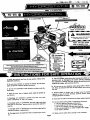
A WARNING
Rotating parts under entire housing
Keep hands and feet away,
78265
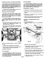
STARTING PROCEDURE EMERGENCY BRAKING
id 15
ER Оч >> e 78269 (ON LEFT HAND
roams tonne ANA | > 5 SIDE OF MOWER PAN) |
Aelesse key and pull throttle down € Col ION Kale ;
Eid, | me a : — К | DISENGAGE —+—————# ENGAGI
Tk ATTACHMENT DRIVE
Вы? ге МАН og. place cuntrul Teves an Pack Start
SAA gr chat Bart god enyasye TEE hoes
arta fu TE AE ELE ATTE CCRT oh EME
Advance thrattie ho choke postion
Turn hay switch Tully to night
WIDTH OF CUT
rant errant ange al Toss RE IRL RITES EREL
AA ECOS
"MODAL TESTID EY NOUPINDENT LABORATORY
Tea 4
“COMPLIANCE WITH CANADIAN RADIO INTE RFERENCE REGULATIONS CERTIFIED
REPLACE SPARK PLUG WITH RESISTOR SPARK PLUG ONLY |
CERTFIE CONFORME AU REGLEMENT CANADIEN SUR LE BROUILLACE RADIOELECTRIQUE
REMPLACER LA ROUGIE PAR UNE ROUGIE A RESISTANCE SEULEMENT |
А WARNING |
ROTATING FAN
… x De nat stand near machine
. white it la In mation.
+ Koop hands, fest and clothing
+ 78280
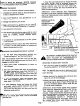
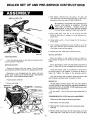
| 1. Know the controls ‘and how to > stop quickly. READ > THE 9. Take y a possible precautions when a leaving the vehicle un
OWNER'S MANUAL. — _ attended, such as disengaging the power take-off, lowering
| the attachment, ‘shifting into park, setting the parking brake,
2. Do not allow children to operate the vehicle. Do not allow | stopping the engine, and removing the key.
adults to operate it without proper instruction.
10. Do not stop or start suddenly when going uphill or down-
3. Do not carry passengers. Keep children and pets a safe dis- - hill. Mow up and down the face of steep slopes; never across
tance away. Е ВЕ | o E. the face. a
4. Clear the work area of objects which might be picked up 11. Reduce speed on slopes and in sharp turns to prevent
and thrown. tipping or loss of control. Exercise extreme caution when
changing direction on slopes. Ш
5. Disengage all attachment clutches and shift into park
before attempting to start the engine. 12. Stay alert for holes in the terrain and other hidden hazards.
6. ‘ Disengage power to attachment, stop the engine and place 13. Use care when pulling loads or using heavy equipment.
shift lever to” Park-Start” position before leaving the operator's a. Use only approved drawbar hitch points.
position. | - b. Limit loads to those you can safely control. |
N ; с. Оо not turn sharply. Use care when backing. m
7. Disengage power to attachment and stop the engine before “d. Use counterweight(s) or wheel weights when sugger
making any repairs or adjustments. | in the owner's manual. |
8. Disengage power to attachment when transporting or not in
use 14. Watch out for traffic when crossing or near roadways.
Page 2
[SEEN e =-5/
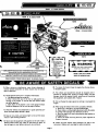
78405 L. H. SIDE STRIPE
A SEAR |
78404 R. H. SIDE STRIPE
| | LOWER === ATTACHMENT «==> RISE
78340
Li
78244 (1 EACH SIDE)
144
DO
\ SELL
IGNITION |
a.
78265
Г y м | “ - ’ y LA
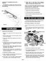
STARTING PROCEDURE EMERGENCY BRAKING + хо“ A IT ENGAGE
1 Place shift over in Neutral = Xx No ' р © ы и a AT TACHME A DR IVE
р ь AN A [Ly
2 Dusenyage attachmant drive
a TR {
к - a В =
3 Advance throttie to choke position, To move tractor with “г © 7
' - . В > К “ 78338
Г. Torn key swatch fully to rghit engine stopped, place
5 Retours hey and pull throttie down
sheoo agite arts
[LIL ET IRL EG IN IT TA
СОСЕТ brake
+ CAUTION WIDTH OF CUT
Hetone dhamauntinig, depgroas pagal fully and engage Brake Loch, 78270
oven age attachimnnt drive, shied Off engine and remuve koy '
compl mt a placa (+) CAUTION
1. Metp al ehleida in place.
2. Belere verviciag machino:
78276
A WARNING
MOOUL TOSTOO EY INDEFINONNT LASORATORY
78226
COMPLIANCE WITH CANADIAN RADIO INTERFERENCE REGULATIONS CERTIFIED
© REPLACE SPARK PLUG WITH RESISTOR SPARK PLUG ONLY !
CERTFIE CONFORME AU REGLEMENT CANADIEN SUR LE BROUILLACE RADIOELECTRIQUE
REMPLACER LA ROUGIE PAR UNE ROUGIE A RESISTANCE SEULEMENT!
— 78400 (UNDER FRONT DECK NEXT TO SPARK PLUG)
— Ma BE AWARE OF SAFETY DECALS
15. When using any attachments, never direct discharge of 20. To reduce fire hazard, keep the engine free of grass, leaves,
material toward bystanders nor allow anyone near the vehicle or excessive grease.
while in operation.
Rotating parts under entire housing.
Keep hands and feet away.
| 3. De net stand near machine
2 while His in motion. ;
4. Keep hands, feet snd clothing
Away Irom pawer.driven parts.
5. Check for snd repair
any damage caused
by striking solid objects
78269 (ON LEFT HAND
SIDE OF MOWER PAN)
78271
21. The vehicle and attachments should be stopped and in-
spected for damage after striking a foreign object, and the
damage should be repaired before restarting and operating
the equipment, see numbers 6 & 7 above.
16. Handle gasoline with care—it is highly inflammable.
a. Use approved gasoline container,
b. Never remove the cap of the fuel or add gasoline to a
running or hot engine, or fill the fuel tank indoors. Wipe
‘up spilled gasoline.
c. Open doors if the engine is run in the garage—exhaust
fumes are dangerous. Do not run the engine indoors.
22. Do not change the engine governor settings or overspeed the
engine.
23. When using the vehicle with mower, proceed as follows:
a. Mow only in daylight or in good artificial light.
17. Keep the vehicle and attachments in good operating con- b. Never make a cutting height adjustment while the engine
~ dition, and keep safety devices in place. is running if the operator must dismount to do so.
| г ¢. Shut the engine off when removing the grass catcher or
18. Keep all nuts, bolts, and screws tight to be sure the equip- | unciogging chute.
ment is in safe working condition. d. Check the blade mounting bolts for proper tightness at
| В frequent invervals.
19. Never store the equipment with gasoline in the tank inside a
“building where fumes may reach an open flame or spark. Al- | 24. Check the grass catcher bags frequently for wear or de-
low the engine to cool before storing in any enclosure. terioration. Replace with new bags for safety protection.
Page 3
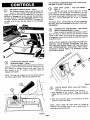
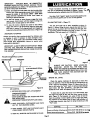
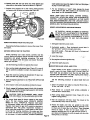
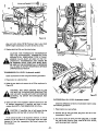
~~ IMPLEMENT POWER CLUTCH — Figure 1
(1) “The implement power clutch is used to operate the
~~ mower or snow thrower, Push the lever forward to
‘engage the clutch and drive the attachment. Pull the lever
rearward to disengage the clutch and stop the attachment.
The lever must be in the rear (disengaged) position to start
the engine. THIS IS A SAFETY FEATURE. The engine will
not start until the lever has been placed in the disengaged
position.
— HYDROSTATIC CONTROL LEVER
O — (Hydrostatic Models — Figure 2
a This lever regulates both tractor speed and direction.
Gradually move the lever forward from the “park-start” (neu-
tral) position to increase forward travel speed. Move the
lever rearward to the “R” position to back the tractor and
regulate reverse speed. |
МОТЕ: The lines and numbers next to the forward slot do
not indicate a given speed. They serve as guide lines only.
Figure 2
Figure 1
THE CONTROL LEVER MUST BE IN THE “PARK-START"
POSITION TO START THE ENGINE.
Figure 3.
| The gear shift lever is used to select any of three '
forward gears or one reverse gear. The markings 1, 2, 3 and
R on the control console indicate the locations of the gears.
The slowest forward gear is indicated by No. 1, the secondary
gear, No. 2 and the fastest gear, No. 3. The “R" indicates
reverse.
THE GEAR SHIFT LEVER MUST BE IN THE FORWARD
NEUTRAL POSITION AS SHOWN IN FIGURE 3 TO START
THE ENGINE.
O PEDAL (Hydrostatic Models) — Figure 1
, When this pedal is depressed, the hydrostatic control
lever will return to neutral and stop the forward or reverse
motion of the tractor. At the same time, the pedal actuates
GEAR SHIFT LEVER — (Gear Shift Models) —
HYDROSTATIC NEUTRALIZER AND BRAKE
“an independent brake which provides an additional means of
stopping the tractor.
NOTE: ALWAYS REMOVE HAND FROM HYDROSTATIC
— CONTROL LEVER BEFORE DEPRESSING THE NEU-
— TRALIZER AND BRAKE PEDAL. THE TWO CONTROLS
ARE INTERCONNECTED. OPERATING THEM SIMUL-
TANEOUSLY COULD. RESULT IN DAMAGED OR MIS- |
ADJUSTED LINKAGE.
Figure 3
(5) CLUTCH BRAKE PEDAL (Gear Shift Models) —
Figure 4
The clutch-brake pedal performs two functions:
1. When depressed to the “midway” range the clutch dis-
engages and the transmission can be shifted to any desired
gear.
2. When the clutch-brake pedal is fully depressed, the brake
actuates and stops the tractor.
NOTE: Always release the pedal slowly for smooth ac-
celeration. Do not allow foot to rest on pedal except for a
clutching and braking functions.
Page 4
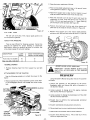
If it becomes necessary to move the tractor with the engine
stopped, rotate the cam arm rearward so the valve actuating
rod is pushed down into the transmission body. After moving
the tractor the cam arm must be returned to the operating
position before the tractor will move with the engine running.
- BRAKE LOCK — Figures 2 and 3
A brake lock is provided on both hydrostatic and
“gear shift models to prevent the tractor from moving
when parked or left unattended.
= ‘To lock the brake, push the brake lock forward with the
foot pedal fully depressed. Then release the foot pedal. IMPORTANT: DO NOT TOW TRACTOR AS INTERNAL
— Figure 2 shows the brake lock engaged. Figure 3 shows it TRANSMISSION DAMAGE COULD RESULT.
disengaged. |
isengag | | y
IMPORTANT: ENGAGE THE BRAKE LOCK BEFORE DIS-
MOUNTING FROM THE TRACTOR OR ANY TIME IT IS
LEFT UNATTENDED.
Figure 6
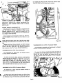
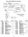
IGNITION AND STARTER SWITCH — Figure 6
The ignition and starter switch has three positions:
U / “off”, “run” and “start”. Start the engine by turning
the key fully clockwise to start position and then release the
key as soon as the engine starts. Stop the engine by turning
Figure 4 the key counterclockwise to the “off” position.
THROTTLE-CHOKE CONTROL LEVER — Figure 6
This control operates both the throttle and choke.
When starting a cold engine, raise the lever past the
- . FREE-WHEELING VALVE (Hydrostatic Models) —
(7) Figure 5
— The free-wheeling valve is provided so the tractor
can be pushed short distances with the engine stopped.
The cam arm, see Figure 5, must be in the forward po-
sition as shown at all times except when it becomes neces-
sary to push the tractor.
~~ ONIN
CAM ARM IN OPER-
<<; ATING POSITION
“
>
offset and into the “choke” position. After the engine has
started, lower the lever to the throttle operating range and
allow the engine to warm at % throttle. Select the appropriate
engine speed in the throttle range after the engine has warmed.
NOTE: Unless otherwise specified, the mower or snow thrower
should be operated at full throttle. The throttle is not to be
used to select desired travel speeds with the hydrostatic
models. Operate at full throttle and regulate ground speed
with the hydrostatic control lever.
LIGHT SWITCH (Optional)—(Figure 6)
If the optional light kit is installed, turn lights on by
pulling the control knob out. Turn lights off by
pushing the knob in; | |
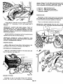
ATTACHMENT LIFT LEVER—(Figure 7) —
The lift lever shown in figure 7 is used to raise and
lower the mower, front blade or snow thrower.
To raise the attachment, pull the lever to the rear until
the latch snaps into the notch provided. This will hold the
attachment in the raised position.
| To lower the attachment, pull the lever to the rear, de-
press the button to release the latch and allow the lever to
move forward. See Figure 7.
3 a
a BR —
STA PULL BACK AND —
НЕ Press BUTTON VS
RAISING THE HOOD—(Figure 8)
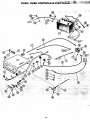
The engine, battery, electrical components, air cleaner, fuel
filter and fuel tank are readily accessible by raising the hood.
To. raise the hood, grasp each side and raise it upwards and
- forward to its stop. | |
RAISING THE REAR DECK — (Figure 8)
The differential, transmission and contro! linkages are
readily accessible by raising the rear deck until the seat rests
against the steering wheel.
FUEL TANK
FILLER CAP
Р Lu
“HOOD LIFT UP
REAR DECK
МНН
+"
ъ
PIZCA En
' a. | =
TRANSMISSION AND
DIFFERENTIAL AREA
FUEL FILTER
| Figure 8
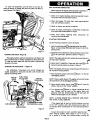
| OPERATION
a forward (neutral) position as shown in Figure 3.
| ‚the “park-start ” position.
- E
PRE-STARTING INSPECTION
Before starting the engine before each day's operation, Ú |
following checks and services should be performed: /
1. Check oil in engine crankcase. Add oil as required to main-
tain proper level. See lubrication section.
. Check fuel supply. Fill with clean, fresh regular gasoline
only. See lubrication section.
. Check air cleaner and service as required.
. Check for engine, transmission or differential oil leaks. See
your authorized Ariens dealer for repairs.
. Make visual checks regarding safety precautions, ob-
structions and maintenance.
STARTING THE ENGINE
Use the following procedure to start the engine:
1. Lock the parking brake( 5 Joy depressing the foot pedal
Figure 4, and pushing the brake lock forward to lock the
parking brake.
2. IYDROSTATIC MODELS. Place hydrostatic contro! lever
in the “park-start’ ' position as shown in Figure 2.
NOTE: The engine will not start unless the control lever is in
(Bin ie
3. GEAR SHIFT MODELS. Place gear shift leve
“NOTE: The engine will not start unless the gear shift lever is in
the “forward” neutral position.
4. Place implement power clutch lever((1)F igure 1, in the rear
(disengaged) position. |
NOTE: This is a safety feature. The engine will not start unless
the clutch lever is in the disengaged position.
5. Raise. throttle choke control leve Figure 6, past the
offset i in the slot to the “choke” position.
. Turn ignition key(B)shown in Figure 6 clockwise aH the
way. Release key as soon as the engine starts and
- -- gradually lower the throttle-choke contro! lever past the
Page 6
offset until the engine runs at a throttle.
NOTE: A WARM ENGINE WILL REQUIRE LESS CHOK- |
ING THAN A COLD ‚ENGINE. a |
If the engine tails to start on the first attempt, turn key
to the “off” position, wait a few minutes and try again. Do
not operate starter continuously for more than 30 seconds at
a time.
Always allow engine to warm up before applying load. ‘
below freezing weather, allow engine to run at a fast idi.
for a period of at least five minutes before moving the
| чай с or starting the attachment. SERIOUS DAMAGE
“TO THE ENGINE AND TRANSMISSION COULD RESULT
ОР THIS PROCEDURE IS NOT FOLLOWED.
ATOPPING THE ENGINE
В Always use the following procedure to stop the engine:
A. HYDROSTATIC DRIVE MODELS. Move hydrostatic con-
‘trol lever to the ‘’park- start” position.
: 2. GEAR SHIFT MODELS. Move gearshift lever to the
— “Neutral” position. |
>
J 3. Disengage the implement power clutch.
| 4. Engage parking ‘brake by depressing the foot pedal (5)
a and by moving brake lock( 6 )forward to “on” position.
5. Lower attachment to the ground.
6. Lower throttle lever and allow the engine to idle for a short
period of time. DO NOT STOP A HOT ENGINE AT HIGH
— SPEED AS INTERNAL ENGINE DAMAGE COULD
RESULT.
7. Turn ignition key counterclockwise to the “oft” position |
| to > stop the engine.
3 8. BE CAREFUL: Remove ignition Key before dismounting
from tractor. This will prevent children and inexperienced
~~ operators from starting the tractor.
yen THE HYDROSTATIC DRIVE TRACTOR
A Start the engine using the procedure explained under
“Pre starting Inspection” and “Starting the Engine.”
NO TE: The hydrosta tic control lever must be in the “park-
start” position and the implement power clutch lever must be
disengaged to start the engine.
| “2. Release parking brake by depressing foot pedal until
SE — brake disengages. |
3. Select the proper engine speed with the throttle-choke
“lever. When operating any power-driven attachment, run
the engine at full throttle (3400 - 3500 RPM) unless
otherwise specified. Use the hydrostatic control lever, NOT
THÉ TH ROTTLE, to select a safe, appropriate travel speed.
| 4. To start the attachment, engage the implement power
clutch with the engine running at % throttle. Then in-
crease e speed to full throttle.
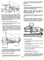
5 “To move the tractor forward and increase the forward |
“travel speed, gradually push the hydrostatic control lever
forward from the neutral position as shown in Figure 9. To
~~ stop or slow down the tractor, pull the control lever back
a © — toward the neutral position.
- guide ! lines s only.
TÉ: The numbers along the forward slot of the console ‚
-do not indica te given speeds. They are provided as
A
CONTROL LEVER IN
POSITION-TRACTOR
STOPPED
To move the tractor backward and to increase the reverse
travel speed, gradually move the hydrostatic control lever
back into the reverse (R) slot from the neutral position. To
stop the tractor or slow down the reverse travel speed,
gradually move the control lever from the reverse (R) slot
toward the neutral position.
IMPORTANT: NEVER OPERATE THE HYDROSTATIC
CONTROL LEVER AND THE FOOT PEDAL SIMULTANE-
OUSLY AS THE LINKAGE COULD BECOME DAMAGED
OR MISADJUSTED.
PARK-START
TRACTOR MOVING FORWARD
CAUTION-MOVE LEVER GRADUALLY,
Figure 9
BE CAREFUL: ALWAYS REMOVE THE IGNITION
KEY WHEN LEAVING THE TRACTOR TO PRE-
VENT CHILDREN AND INEXPERIENCED ОР-
ERATORS FROM STARTING THE ENGINE.
OPERATING THE GEAR SHIFT TRACTOR
1. Start the engine using the procedure explained under
"'Pre-starting Inspection” and “Starting the Engine.”
NOTE: The gear shift lever must be in the forward neutral
position and the implement po wer r clutch lever disengaged
to start the engine.
2. Release brake lock by depressing the clutch- brake pedal,
Figure 10, until the lock disengages.
. Depress clutch-brake e peda approximately halfway (into
the shifting range) as shown in Figure 10. Place gear shift
lever into the desired gear and slowly release the e pedal
to provide smooth acceleration.
IMPORTANT: DO NOT FORCE GEAR SHIFT LEVER IF
GEAR DOES NOT ENGAGE. RETURN LEVER TO NEU-
TRAL, RELEASE PEDAL AND REPEAT THE PRO-
CEDURE. THE CLUTCH-BRAKE PEDAL MUST BE IN
“THE SHIFTING RANGE TO ENGAGE ANY SELECTED
Page 7
GEAR. DEPRESSING THE PEDAL TOO FAR LOCKS
THE TRANSMISSION MAKING IT IMPOSSIBLE TO
SHIFT GEARS. DEPRESSING THE PEDAL TOO LITTLE
WILL CAUSE GEAR CLASH AND POSSIBLE DAMAGE
TO THE TRANSMISSION.
CONTROL LEVER IN FORWARD SLOT-
— IMPORTANT: TRACTOR MUST BE COMPLETEL Y
STOPPED WHEN SHIFTING GEA RS. SERIOUS TRANS-
MISSION DAMAGE CAN RESULT IF GEARS ARE SHIFT-
… ED WITH TRACTOR IN MOTION.
4. Select the desired throttle speed with the throttie-choke
control lever. When operating a power-driven attachment,
operate the engine at full throttle {3400 - 3500 RPM)
unless otherwise specified and control travel speed by
selecting an appropriate gear.
Proper lubrication according to a regular schedule is a
vital part of maintaining the Model S-8 Garden Tractor. The f
following lubrication schedule should be followed closely.
Use clean, fresh regular” grade of automotive gasoline. Do
not use premium gasoline. Do not mix oil with gasoline.
5. To start the mower or snow thrower, engage the imple-
ment power clutch slowly with the engine running at %
throttle, then increase speed to full throttle,
— 6. To stop the tractor, depress foot pedal to the braking
range, then return it to the shifting range and place gear
shift lever in neutral. Fully depress pedal and engage the
| brake lock when parking or leaving the tractor. (Figure 10)
FILLING THE TANK — (Figure 11)
The fuel tank filler cap is easily accessible as shown in
Figure 11. Before filling the tank, wipe all dust and dirt from '
around the cap to prevent dirt from falling into the tank. Use
an approved gasoline container and keep it clean. Fill tank
completely. The tank capacity is 1-3/8 gallons.
… EMERGENCY STOPPING > |
o
Always use caution when mowing--be alert for children, pets
or obstacles in path. If necessary to make emergency stop,
- - step firmly on brake pedal. (On hydrostatic model tractor,
drive control lever automatically returns to neutral when
brake pedal is depressed.)
IMPORTANT: ALWAYS REMOVE IGNITION KEY WHEN
LEAVING THE TRACTOR TO PREVENT CHILDREN
"AND INEXPERIENCED OPERATORS FROM STARTING
THE ENGINE.
a
—
"PTO DRIVE CONTROL LEVER
DISENGAGED . ENGAGED
Figure 1 A
RO ALWAY Ys USE CAUTION WHEN HANDLING
GASOLINE. NEVER FILL THE FUEL TANK
WHEN THE ENGINE IS RUNNING OR WHEN THE
“ENGINE IS HOT. NEVER SMOKE WHILE FILLING
— CLUTCH BRAKE PEDAL
D-ENGAGED |
”
| | THE TANK. REMOVE THE IGNITION KEY BE-
Sumi FORE FILLING TANK
7 RANGE
/ Spano ENGINE OIL LEVEL
et RANGE
- 4 , | “Check the engine crankcase oil level daily or every five
“mY И hours of operation. The oil level should be maintained to the -
—— — “Full” mark on the dipstick, Figure. 12. Never allow the oil
e A level to fall below the “Add” mark or serious engine damage
BE CAREFUL . Figure 10 could result. DO NOT OVERFILL. Oil level must never
exceed the “full” mark. Oil capacity is 2% us. pints.
+ BEFORE SERVICING ANY ATTACHMENT: -
DISENGAGE POWER. | To check the oil, place the tractor on a level surface, stop
Ш SHUT OFF ENGINE. ‘the engine and wipe all dirt and dust from around the dip-
stick, Figure 12. Pull dipstick out, wipe off the oil and re-
insert by pushing it down tightly (until it snaps into place).
Pull dipstick out and observe the oil level. Add sufficient oil
of the proper viscosity (see chart) to bring. the level up | to > the _
“Full” mark. |
| " MAKE SURE BLADES OR AUGER HAS STOP-
"a PED REVOLVING. |
a A. “DISCONNECT ENGINE SPA RK PL UG CABLE.
2 KEEP CHILDREN, BYSTANDERS AND PETS
OUT OF THE WORKING АВЁА. |
| SERVICE | OIL TYPE
3 KEEP HANDS, FEET AND CL OTHING AWAY
FROM POWE R DAI VEN PARTS. Lawn and Garden Attachments | Ariens SAE 10W-30 MS or equivalga
Ariens SAE 5W-20 MS or equiva.
4 KEEP ALL SHIELDS AND GUARDS IN PLACE. Snow Removal Equipment
Page 8
ENGINE OIL. DRAIN PLU
O NT Hy
ENGINE OIL DIP STIC
TADA
—
„бе
IMPORTANT: ENGINE WILL SMOKE EXCESSIVELY IF
DIPSTICK IS NOT PUSHED DOWN UNTIL IT SNAPS
INTO PLACE.
CHANGE ENGINE CRANKCASE OIL
When the tractor is new, the oil should be changed after the
— first five hours of operation. Thereafter under normal
operating conditions the oil should be changed every 25
hours of operation. If extremely dusty or dirty conditions pre-
vail, change oil more frequently.
to. TA
Co “Drain crankcase by removing the oil drain plug, Figure 12,
while the engine is warm. Allow the oil to runinto a con-
—— tainer.
NOTE: With the engine warm, the oil will flow more freely
- permitting more contaminants to be drained from the crank-
Replace drain plug. Remove dipstick and refill crankcase
“with 2% U.S. pints of the proper type and viscosity of oil as
shown in the chart. Check oil on the dipstick to determine
that the level is to the “Full” mark. DO NOT OVERFILL.
TRANSMISSION OIL LEVEL (Gear Shift Models)
The transmission oil level should be checked monthly
or every 25 hours of operation.
To check the oil level, place tractor on a level surface,
— raise the rear deck and remove the “check plug” from the rear
of the transmission as shown in Figure 13. The level is
correct when oil seeps out of the check plug hole. If the
level. is below the check plug hole, remove the filler plug
from the top of the transmission and add Ariens Premium
~ Gear Lube SAE 90 MP until the proper level is reached.
DIFFERENTIAL OIL LEVEL (Hydrostatic Models)
Fd
~The differential oil level should be checked monthly or
~~ every 25 hours of operation.
To check the oil level, place the tractor on a level surface,
raise the rear deck and remove the “filler plug” at the rear of
the differential, Figure 14. The level is correct when the lubri-
Page 9
cant reaches the filler plug hole. Add Ariens Premium Gear
Lube SAE 90 MP until the proper level is reached.
N i i \
ar
5 4 я |
A = Ÿ
; 7 N \
+ rd
IL FILLER PLUGHA ———
а [4 xl =
F Ё
in |
Figure 13
TRANSMISSION OIL LEVEL (Hydrostatic Models)
The hydrostatic transmission oil level should be checked
monthly or every 25 hours of operation.
To check the oil level, raise the rear deck and clean all
dirt and dust from the oil expansion reservoir area, Figure 15.
Remove cap from the reservoir and observe the oil level.
The level is correct when the reservoir is % full at ambient
temperature.
FILLER AND OIL LEVEL PLUG ON
HYDROSTATIC DIFFERENTIA|
L
ve
- Figure 14
NC A 7
EXPANSION RESERVOIR
A
If the reservoir is less than % full at ambient temperature,
‚add TYPE “A” transmission FLUID until proper level is
obtained.
Ц
Figure 15
IMPORTANT: ALWAYS USE NEW, CLEAN, TYPE “A”
TRANSMISSION OIL AND BE EXTREMELY CAREFUL
NOT TO ALLOW ANY FOREIGN MATTER TO CON-
= TAMINATE THE OIL AS SERIOUS TRANSMISSION DAM-
AGE COULD RESULT. | |
DO NOT OVERFILL the reservoir as the oil expands during
operation and may leak out around the cap.
IMPORTANT: PROPER OIL LEVEL IS ESSENTIAL FOR
FULL BRAKING EFFECT AND PROTECTION AGAINST
SEVERE TRANSMISSION DAMAGE. *
STEERING GEARS
| | Apply a light coat of Ariens Moly Lithium grease to the
steering gears every 50 hours of operation. See Figure 12.
INTERMEDIATE STEERING SHAFT
Apply oil to the bearing surfaces of the blocks every 50
hours of operation. See Figure 16. a
RPT TPA LD
CL J. by
A В NINTERME IATE STEERING
[JOR + [A ¿e
o Figure 16
GREASE FITTINGS
— Following is a list of the grease fittings with reference
numbers that identify each location on the corresponding
pictures. Figures 17 & 18. Each fitting should be wid |
before and after lubrication. Grease each fitting ever
hours of operation with Ariens Moly Lithium grease.
1. Figure 17 — Right and left king pin. |
2. Figure 17 — Right and left front wheel. |
3. Figure 18 — Hydrostatic control arm pivot
{hydrostatic models)
POINTS TO OIL
Periodically oil the lift point pivots, front axle pivot,
trol linkage pivots and the floating intermediate shaft pi
to insure long life and smooth operation of the parts.
There is no lubrication required on the mower.
IMPORTANT: KEEP GREASE AND OIL OFF THE BEI
TOPREVENT BELT SLIPPAGE AND DETERIORA TIO!
AS)
o
\
)/
Y,
NT
y UN
( Y
A
)
0
AN
{i MR \
©)
ое
||
4
|
5,
aL
|
|
И
nn
e
в e DH
URL
Ly
3
Dr
Fig
iy
\
Page 10
„MAINTENANCE
GENERAL
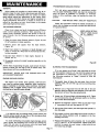
| TRANSMISSION COOLING SYSTEM
Dirt and grime accumulations on transmission cooling
ва fins can cause overheating. Check and clean the cooling fins
BR quired to keep the Lawn Tractor operating at peak efficiency. every 50 hours of operation or quarterly. In extremely
~~ Ariens Company recommends that you contact an Ariens dusty or dirty conditions, clean the cooling fins more fre-
“dealer before making any adjustments to this tractor. Refer quently. | |
to the engine instruction manual and engine nameplate for о
~~ engine maintenance instructions. If repairs or service are re-
… quired for the engine, see your Ariens dealer or the nearest
“authorized engine service station,
A AIR CLEANER SERVICE
Ariens dealers will provide any service which may be re-
— CAUTION: KEEP WATER AWA Y AND OFF RESER VOIR.
Check the hydrostatic cooling fan blades periodically to
assure that the blades are not bent or broken and that the fan
is in good condition.
“Clean the air cleaner and re- ой the element every 25 hours
under normal operating conditions. When operating in ex-
-tremely dusty conditions, perform this service at more fre-
— —quent intervals, Use the following procedure to service the
air cleaner: | |
KEEP AREAS W WITHIN
HEAVY LINES CLEAR
OF ALL DEBRIS
о 1. Raise the tractor hood. Remove screws A, Figure 19, and
lift off complete air cleaner assembly. |
2, Remove | screen and spacers from the foam element,
co Figure 19. | o
— 3. Wash foam element in kerosene or r liquid detergent and
© water to remove dirt. Wrap foam i in cloth and squeeze dry.
Let dry overnight. - E.
_ 4. Saturate foam element in clean engine. Squeeze to
remove the oil,
5. Re-assemble parts and re- “install complete assembly on the
carburetor. *
— NOTE: When re-assembling the parts, make certain the foam
element extends over the edge of the air cleaner body. The
— foam element will form a protective seal,
“IMPORTANT: NEVER RUN THE ENGINE WI TH THE
В AIR CLEANER REMOVED!
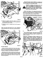
oo ENGINE COOLING SYSTEM
_ © The engine is air cooled. Grass particles, chaff and dirt
may clog the cooling system, especially when mowing dry
“grass or operating in extremely dusty conditions. Continued
— operation with a clogged cooling system may cause severe
oo overheating and possible engine damage.
POSITION TANGS AS SHOWN
Figure 19
It is essential that the rotating screen, engine cooling fins
5 and the exhaust system be kept free of dirt and debris which
Co could cause the engine to overheat.
To avoid overheating and possible engine damage, period-
ically remove the shrouding from around the cooling fins,
“Figure 20, and clean the area shown within the heavy black
line of all grass, dirt or chaff accumulation.
“ Figure20
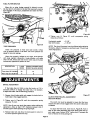
BLEEDING THE TRANSMISSION
If for any reason the oil level is ever permitted to fall be-
low the expansion reservoir, air may enter the system causing
the transmission to malfunction. If this should occur, use
the following procedure to “bleed” (remove air from the
transmission):
1. Thoroughly clean all dust, dirt and grime from the free- |
wheeling valve, the oil filler cap and surrounding areas,
Figure 21. |
2. Remove nut A, Figure 22 from the left end of the cam
assembly shaft and slide the cam assembly to the right until
the cam arm is free of the valve actuating rod.
3. Loosen nut B first and then valve actuating rod C, Figure
21, and remove the rod. Be extremely careful not to allow
dirt to enter the transmission.
4. Remove the expansion reservoir filler cap and add “Type
A” transmission fluid until the reservoir is Y full.
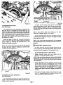
5. Jack uprear of the tractor, start the engine and d operate at a
— slow idle speed. |
6. With engine running, move speed control lever to both for-
ward and reverse positions until oil appears at the free-
wheeling valve hole. |
7. Replace free-wheeling valve actuating rod C and tighten
nut B, Figure 21, to 30 inch-pounds. Tighten both parts
carefully to prevent the small rubber o-rings inside the cap
from becoming damaged.
|
e \
LJ
(PN € N
ANN OIL
a N
| `
- 14
FILLER CAP
эм‘
ом. RESERVOIR
И
“EXPANSI
=
Figure 21
8. Replace cam assembly, Figure 22. Tighten nuts A so the
cam arm intersects the center of the valve actuating rod
and the shaft has 1/32” end play.
9. Recheck the oil level. if necessary add oil until the reservoir
is half full.
NOTE: THE CAM ARM MUST BE IN THE FORWARD
POSITION BEFORE THE TRACTOR CAN BE OPERATED.
» CAM ARM IN
OPERATING POSITION
ZA, |
Figure 22
BATTERY SERVICE
Check the battery electrolyte level once each week or
— every 25 hours of operation. Check it monthly if the tractor
is idle or is in storage. Add distilled water to bring the level to
the bottom of the split ring in the filler tube of each cell.
Each spring and fall clean. the battery and terminals with
ammonia or bicarbonate of soda solution followed by flushing
~ with clean water. Keeping the battery clean will prolong
battery life. After cleaning, apply a light coat of grease to the
terminal and cable ends.
Keep cable clamps securely tightened to terminals and .
keep battery hold-down clamps tight to prevent vibration but
do not overtighten as this could warp the case.
WARNING: STORAGE BATTERIES GIVE OFF.
HIGHLY INFLAMMABLE HYDROGEN GAS. L —
NOT ALLOW SPARKS OR FLAME NEAR BA
TERY. DO NOT LAY TOOLS ACROSS BATTERY
TERMINALS WHICH MAY CAUSE A SPARK
RESULTING IN AN EXPLOSION,
Maintain the battery at full charge during storage and
during the winter months to prevent freezing. When water is
added during freezing weather, run the engine at least one
hour to bring the battery up to a full state of charge.
NOTE: Figures 26 and 27 show the right rear tractor tire re-
moved for clarity and for easier access to the brake adjustment
POSITIVE (+)
in
TERMINAL A 7 / NEGATIVE (—) TERMINAL
\ xf
RA
Figure 23
When installing the battery, make certain the ground cable
is connected to the negative (—) terminal on the battery, see
Figure 23. Be sure the battery cable is connected to the
45 % L.
positive (+) terminal.
IMPORTANT: REVERSED BATTERY CABLES OR RE-
VERSED CABLES FROM A BATTERY CHARGER OR
BOOSTER BATTERY CAN BLOW THE 7% AMP FUSE
SHOWN IN FIGURE 24. ALWAYS DISCONNECT THE
TERMINAL AT THE FUSE WHEN CHARGING THE BAT-
TERY OR WHEN ELECTRIC WELDING IS DONE ON THE
TRACTOR. a
7-4 AMP FUSE
Lu
ee,
=
o el
Figure 24
— FUEL FILTER SERVICE
>
“ TIRE PRESSURES
When dirt or other foreign material is allowed to enter
the fuel tank it will collect in the fuel filter eventually causing
- fuel stoppage. If this occurs, disassemble and clean the filter,
wt 25. |
Figure 25
Check tire pressures at least once each month. Inflate
tires to pressures shown in the chart. Use a low pressure tire
gauge for accu rate readings.
Keep tires properly inflated at all times. Over- inflation
will cause operator discomfort. Under-inflation will cause
short tire life. Always see that the tire valve caps are in place
and securely tightened to prevent air loss.
DESCRIPTION SNOW THROWER AND
LAWN
WORK |FRONT BLADE WORK
Front tires (15 X 6.00-6)| 10 12
Rear tires (20 x 8.00-10)| 6 6
ADJUSTMENTS
| BRAKE ADJUSTMENT
ОН the -brake does not hold or stop the tractor, or if it is
extremely difficult to engage the brake lock, it is necessary
to adjust the brake. Use the following procedu re.
- 1. Depress clutch brake pedal and engage the brake lock to
_ hold brake in the engaged position.
| 2. Tighten nuts A, Figure 26, until the compression spring
> measures 1% inch.
NO TE: Nuts B must not touch the support when making the
adjustment. Allow at least 1/16” clearance between nuts В
and the support when adjusting the spring length.
3. Release brake lock and allow the brake pedal to return to
its normal position against the stop.
Figure 26
4. Tighten nuts B, Figure 27, until compression spring
measures as follows:
— 2-1/8"
— 1-15/16”
Hydrostatic models
Gear shift models
NOTE: The clutch free-travel may be affected after adjusting
the brake. Adjust if necessary as outlined under “Clutch Free
Travel Adjustment.”
a —
A oROSTADE MODELS—2-1 —
LL
GEAR SHIFT MODELS- Ei \ —
eo!
AN BRAKE peo
NS NE
[|
Figure 27
CLUTCH FREE TRAVEL ADJUSTMENT
(Gear Shift Models)
The clutch rod must be adjusted to insure that the trans-
mission drive belt is fully engaged when the clutch brake pedal
is released.
To adjust the free travel, move nuts A, Figure 28, front or
back so that when depressing the clutch brake pedal the sup-
port angle moves forward 3/16” before bolt B contacts the
front of the slot in the clutching link.
Page 13
Figure 28
TRANSMISSION DRIVE BELT
В (Gear Shift Models)
The transmission drive belt idler should be adjusted if the
drive belt slips or if the spring coils have bottomed out. See
| Figure 29. Adjust by loosening bolt A and moving the idler
back in the slotted hole of the mounting bracket until the belt
does not slip and until there is clearance between the spring
coils. Before tightening bolt A, place the belt guide 1/8" from
the belt in such a position that it does not bind the belt in
‘any position of the idler,
‘Check belt quide D, Figure 30. It should be positioned
1/8” from the belt at the point where the belt enters the drive
sheave. Adjust by loosening the ‘mounting | bolt A and
positioning the guide: as required. -
| NOTE: The clutch free-travel n may ; be affected after adjusting
‘the drive belt idler. Adjust if necessary as outlined under
— “Clutch Free Travel Adjustment.”
TRANSMISSION DRIVE BELT —
Вон
i a Zia
ay
ep SPRING a
Figure 29
INTERMEDIATE SHAFT DRIVE BELT
(Gear Shift Models)
The intermediate shaft drive belt should be tightened if it
begins to slip or before the idler bracket contacts the stop
bolt as shown in Figure 30.
——— -
Зла a
A iE .
| 0— < LS eX (+E <
B=
STOP BOLT! Y ==
/ a PLATE u
Gas Ш
Sul Ey mW
A INTERMEDIATE SHAFT)
DRIVE BELT
SHAFT A TO HEAR OF I
TRACTOR FRAME WITHIN Ine"
p— B
- - Figure 30
To adjust the belt tension, loosen the four intermediate
shaft mounting bolts A and B, Figure 30, and move the shaft
rearward keeping it parallel to the rear of the tractor frame
until the front edge of the idler bracket is flush with the plate
identified at C.
NOTE: THE SHAFT MUST BE PARALLEL TO THE
TRACTOR FRAME WITHIN 1/16 INCH.
Adjust belt guides D and E 1/8" from the belt at the points
where the belt is tangent to the sheave and tighten the shaft
mounting bolts A and B. |
NOTE: The clutch free-travel adjustment can be affected
‘ after tightening this belt. Re-adjust as previously outlined #
a pecessary. |
go DRIVE BELT (Implement Power)
“The PTO drive belt should be adjusted before the rear
nuts B, Figure 31, contact the pivot block when the imple-
ment power clutch is engaged or if the belt begins t to slip.
Use the following procedure to adjust the belt:
1. Engage implement power clutch and sichten nuts ©. en
Figure 31, until the spring length is 2-5/8". gee eh
| NO TE: When making this adjustment, there must be clearance .
— between the rear nuts B and the pivot block. Move nuts B °
rearward if necessary to obtain this clearance before measuring
- ths spring length.
Page 14
2.
Position belt guides D and E, Figure 32, across from € one
“another when the clutch is disengaged in such a manner
that the belt is retained in the disengaged position. in ad-
dition, guide D must clear the engine sheave by 1/8" as the
clutch is moved from the disengaged to the engaged
position. Move guide D rearward if necessary to obtain this
clearance.
. with clutch disengaged, tighten nuts B, Figure 31, to ob-
tain 1/4” clearance between the implement power clutch
lever and rear of siot in the tractor frame. |
- ENGINE
— CRANK SMAFY
PTO DRIVE OVERCENTER ASSEMBLY
CONTROL
LEVER
PTO DISENGAGED O
Figure 31
- VW after adjustment, the rear nuts 8, Figure 31, contact the
“pivot block when the clutch is engaged, loosen bolt F, Fig-
ure 32, and move the idler closer to the belt to provide ad-
ditional adjustment, Repeat the complete adjustment se-
quence if it becomes necessary to move the idler.
PTO ENGLGED
ere,
к,
"
No A: wir ave. MUST cLean ^
(Vena er 178
“+
a...
*s
+
",, er”
x *
. *
e : +
* +
- ot + :
” : +
we =
*. ”
. . ”
- a Ll в +
A A
a" wre
м oe, a,
a» 4 e "
- . $
” ‘Ре. *
”
„ 2 "ero e #,
Pa a NE,
Ру ” #5 Talley "
+
A TG \
- + * # #, >
Figure 32 “. ::7 1°
+
` 10" Tee. ... 7
HYDROSTATIC TRANSMISSION DRIVE BELT
(HYDROSTATIC MODEL ONLY) | a
- The hydrostatic drive belt does not require tightening.
Belt tension is achieved by a spring-loaded idler. Replace the
- belt if it has stretched or worn to the point where it begins to
- slip.
"HYDROSTATIC NEUTRALIZER PEDAL ADJUSTMENT
(HYDROSTATIC MODEL ONLY)
a - The linkage should be adjusted to automatically return the
- hydrostatic contro! lever to the “park-start”” (neutral) position
when the neutralizer pedal is depressed.
To adjust the neutralizer pedal, place control lever in the
‘’park-start’’ position, loosen bolt A, Figure 33, depress the
foot pedal and apply the brake lock, then retighten bolt A.
return to
Ч м:
/ ww
JN CAM
<
"FRICTION i)
Figure 33
Release brake lock, move the control lever to a forward
position then depress the foot pedal. The control lever should
“park-start” (neutral). Repeat process by placing
control lever in reverse. When the adjustment is properly made,
the control lever will automatically return to neutral from
either forward or reverse when the neutralizer pedal is
depressed.
IMPORTANT: NEVER DEPRESS BRAKE PEDAL AND
MOVE THE HYDROSTATIC CONTROL SIMULTANEOQUS-
LY. THE LINKAGE IS INTERCONNECTED AND DAMAGE
OR MIS-ADJUSTED LINKAGE COULD RESULT.
HYDROSTATIC NEUTRAL ADJUSTMENT
(HYDROSTATIC MODEL ONLY) |
The hydrostatic controls should be adjusted so the rear
tires stop rotating when the control lever is returned to
neutral either manually or with the neutralizer pedal.
Use the following procedure to adjust neutral:
“1. Check HYDROSTATIC NEUTRALIZER PEDAL ADJUST-
Page 15
MENT. If required, adjust as previously explained.
. Check position of the timing mark on control cam. With
the shift lever in the “park-start” position and brake lock
engaged, the center line of bolt head B, Figure 33, should
be aligned with the timing mark on the cam. If the
timing mark does not align with the bolt head, loosen bolt
C and move the cam up or down as required to align the
bolt head with the timing mark. Tighten nut C securely
after making the adjustment.
. Jack up rear of the tractor until rear tires are clear of the
ground. |
. Start engine and increase speed to full throttle.
. Loosen bolt B slightly. Insert a screw driver through the
slots in the friction plate and the pintle lever, Figure 33.
Pivot the pintle lever left or right until the rear tires stop
rotating and retighten bolt B.
WARNING: KEEP HANDS AND ANY LOOSE
CLOTHING AWAY FROM THE HYDROSTATIC
COOLING FAN AND DRIVE BELT WHEN MAK-
ING ADJUSTMENT. THESE PARTS MUST RO-
D TATE WHEN MAKING THE NEUTRAL ADJUST-
MENT. )
HYDROSTATIC CONTROL LEVER BRAKE ADJUSTMENT
The ‘hydrostatic control lever friction brake must be ad-
ВЕ justed so the control lever moves through the “torward'* and
“reverse” modes with a minimum of force. However, due to
the neutral tendency of a hydrostatic transmission to neu-
tralize, the brake must be tightened sufficiently so the trac-
— tor maintains any selected speed setting.
To adjust the friction brake, tighten or loosen bolt D,
Figure 33, until the proper braking is reached.
FRONT WHEEL TOE-IN ADJUSTMENT
- Proper toe-in of the front wheels is necessary to assure
proper steering and to reduce tire wear. Correct toe-in is
when the front of the wheels are 1/8” to 1/16” closer together
“than the rear of the wheels (measured at the horizontal
center line of the rim flanges).
If the steering develops a wandering characteristic or if
— excessive tire wear develops, the toe-in of the front wheels
should be checked. If the toe-in is not correct, adjust as
| follows: | |
1. Turn steering whee! until the rear edge of the tie rod
connecting link is perpendicular (90 degrees) to the
tractor frame as shown in Figure 34. |
. Adjust length of tie rods until distances A and B are equal
and so distance с 15 between 1/8” to 1/16” less than
distance D.
Ё RED CONNECTING | LINK E
NO TE: Use following procedure. to shorten or r lengthen
| tie rods: co ay
1. Loosen jam nuts on 1 both ends of tie rods, Figure 34.
— 2, Rotate tie rods until distances A ‘and B, Figure 34, are
equal and distance Ci is 1/8" to 1/ 16” less than D.
3. Tighten jam nuts securely. E
SEAT ADJUSTMENT
The seat is adjustable front or back to any one of six dif-
ferent positions. Adjustment is made by removing the four
mounting bolts located under the seat, moving the seat to the
most comfortable position and then replacing the mounting
bolts in the appropriate holes.
Page 16
Au A AN TM Te
E L EP EME ACA AA CA e. "e E A
If it becomes necessary to replace one of the tractor
drive belts, the following diagrams show the proper place-
ment of the belts and belt guides. After installing a belt it -
will be necessary to follow the adjustment procedures out’
lined i in the ADJUSTMENT section of this manual.
PTO DRIVE BELT — (Figure 32)
1. Adjust guide A to clear the engine drive sheave by 1/8 inch.
2. Adjust guide G to clear the floating jackshaft sheave by
- 1/8 inch.
. Position idler F to provide least amount of belt tension
when installing a new belt.
. Adjust belt tension and guides D and E using the procedure
outlined in “Maintenance and Adjustment” section.
MECHANICAL TRANSMISSION DRIVE BELTS —
(Figure 35)
Intermediate Shaft Drive Belt
Follow the instructions outlined in the ADJUSTMENT
section.
Figure 35
Transmission Drive Belt (Figure 35) Do
e E “es
1. Position guides A ‘and B 1/8" from drive sheave at the
points where belt is tangent to the sheave.
. Position gu ide D, 1/8” from the transmission sheave.
E
least amount of belt tension when installing : a new belt.
. Place guide C 1/8” from the belt in such a position that i
does not bind the belt in any position of the idler.
ADJUSTMENT section.
. Idler E is mounted in a ) slotted hole. Position to provide
CE
. Adjust belt tension using the procedure outlined in
BEKOMME
_ HYDROSTATIC TRANSMISSION DRIVE BELT —
(Figure 36)
No adjustments are necessary when replacing the hydros-
— tatic transmission drive belt. Belt tension is maintained by the
- spring-loaded idler.
h
*
a
*
“a, E :
" +
. " * ‘
"a . + 4 “
- я LI
ey . ; 4
- *, .
+, ,
‘ > г de LAT)
+ , .. 6.
+ “
* : " #
J “„ FA ,
7
+ "
- " =" Te, a
tL a - re te, e . Г)
. r + . e, »
Fi u 36 “ aaa ° fe, 3,
" = x “ e.»
igure if.
. ; "os wy, Trl Ы
- vw Joo ел :
- NL A : : No \
>. A *. 7
\ Nc `
O4 \ A ,
PREPARATION FOR STORAGE
1. Remove all oil, grease and dirt from engine and trans-
mission.
. Clean the tractor exterior and tires thoroughly, removing
all mud, dirt and grease.
. Touch up all unpainted and exposed areas with paint to
prevent rust.
. Change engine oil.
. Disconnect fuel line at fuel filter and drain fuel tank. Run
the engine until the fuel is exhausted from the system.
Clean the fuel filter.
. Remove and clean battery. Check electrolyte level and
‘have battery fully charged. Store battery in a cool, dry
place where it will not freeze. |
. Remove the spark plug and pour one tablespoonful of
SAE 30 oil into the cylinder. Turn engine over manually
at least two revolutions.
. Re-gap spark plug. Replace if required.
. Check transmission and differential oil levels. Add oil as
required. Lubricate tractor thoroughly.
. Store tractor in a cool, dry place to reduce tire deterio-
ration. Block up tractor to take the weight off the tires.
Page 17
11. Inspect tractor for visible signs of wear, breakage or
damage. Order any parts required and make necessary
repairs to avoid delays when starting next season.
NOTE: Your authorized Ariens dealer is trained and equipped
to service your tractor. A periodic check-up by your dealer
will help to reduce your maintenance costs.
PREPARATION FOR USE AFTER STORAGE
1. Replace battery and check electrolyte level.
2. Fill fuel tank with fresh, clean regular gasoline.
3. Check transmission, differential and engine oil levels.
4. Check tire inflation.
36 RM ROTARY MOWER
The Model 36 RM Rotary Mower is standard equipment
on both the S-8 Gear Shift and Hydrostatic tractors.
ATTACHING THE MOWER TO THE TRACTOR
Use the following procedure to attach the mower to the
tractor:
1. Remove ignition key. Place implement power clutch lever
‚ in the “disengaged” position and “engage” the tractor
brake lock.
Fd
MO INPLEMENT POWER CLUTCH
и
CUTTING HEIGHT
ADJUSTMENT LEVER,
ha —
(A OY
NA FRONT SUPPORT BAR
LOWEST м
TTACHING PINNTRACTOR LIFT ARMS
CUTTING AND HAIR PIND-. Fioure 37
POSITION COTTER igure
2. Raise the tractor attachment lift lever. Figure 7.
3. Place cutting height adjustment lever in the second lowest
cutting position, see Figure 37.
. Raise front support bar to clear the front tractor tire and
slide the mower under the tractor from the right side.
. Place the drive belt over the rear lift point and lower the
attachment lift lever. Align ball joint of rear lift point to
tractor lift arms and secure with the “L” shape attach-
ing pin and hairpin cotter provided, Figure 37.
6. Position drive belt over the drive and driven sheaves and
place idler to the inside of the beit as shown in Figure 37.
7. Position front support bar in the tractor saddle brackets
-— and secure with the locks and latches, see Figure 38.
<
il. =
SADDLE BRACKET ©
| — FR
ONT $
; REMOVING MOWER FROM THE TRACTOR
Reverse the attaching procedure to remove the mower from
the tractor.
BEFORE OPERATING THE TRACTOR
Before operating your rotary mower, carefully read this
manual. Become thoroughly familiar with the controls, safety
precautions and proper operating procedures. The more
— familiar you become with the tractor and ı mower the better
| results you will have. Fag ES DE
. Ns ЗИ.
— Use the following procedure to operate the mower:
4. Move cutting height adjustment lever, Figure 37, to one of
— the six positions available to obtain the desired height of
eut Co |
Figure 38
° 3 Lower the mower. - |
= 3:
4. Stop engine and remove ignition key.
travel speeds may cause the ‘engine to stall and then mower | ro
to plug or a drive belt to slip.
7. For any emergency or “panic” stops, depress the clutch
brake pedal on gear shift models or the neutralizer and
brake pedal on the hydrostatic models.
NOTE: KEEP FOOT OFF PEDAL DURING —
OPERATION. NEVER USE PEDAL AND HYDROSTATIC
CONTROL LEVER SIMULTANEQUSLY AS THE PARTS
ARE INTER-CONNECTED AND THE LNIKAGE COULD -
BECOME DAMAGED OR MISADJUSTED. ON GEAR SHIFT
MODELS, BELT SLIPPAGE COULD OCCUR.
MOWER ADJUSTMENTS AND MAINTENANCE
BE CAREFUL: NEVER ATTEMPT TO SERVICE
OR MAKE ANY ADJUSTMENTS TO THE MOWER
WHILE THE ENGINE IS RUNNING. WHEN SER-
VICING OR MAKING ADJUSTMENTS, IT IS A
GOOD PRACTICE TO USE THE FOLLOWING
PROCEDURE:
1. Disengage implement power clutch.
2. Hydrostatic models — Place hydrostatic control lever in
the “park-start” position and apply brake lock.
Gear shift models — Place gear shift lever in first gear and
apply brake lock.
+= 5 Disconnect spark plug wire,
“fanta BLADE LEVEL AND PITCH
2. Raise the mower r by ‘pulling the attachment | lift lever rear-
Si ‚ward until the lock snaps in 7 place.
Вы 3, Sc the engine a as outlined i in the TRACTOR OPERATION
| 4.0 Drive tractor t to the work 8 ares before starting the mower,
5. Slowly engage the implement | power clutch with the engine
— running at % throttle. Increase engine speed t to full throttle
Е after the blades are rotating.
* CAUTION: KEEP BYSTANDERS AWAY FROM
THE AREA WHI LE THE BLADES ARE ROTA TING.
mA “hin i PA
6. The mower blade speed i is directly related to the engine
o speed. For best mowing results, OPERATE ENGINE
— SPEED AT FULL THROTTLE. Regulate travel speed
- on hydrostatic models with the hydrostatic control lever.
Regulate travel speed on gear shift models by selecting an
appropriate gear. The power requirement increases in
dense, high grass conditions. If travel speed of the tractor
is too fast for mowing conditions, the engine and thus
the mower will slow down reducing the cutting efficiency
of the mower. In some conditions, excessive FORWARD.
Page 18
Proper leveling of the blades is essential in obtaining a
smooth, evenly cut lawn. Blade pitch is correct when the
front blade tips are slightly lower than the rear blade tips.
Improper pitch adjustment will affect engine power require” a
ments and can cause uneven cutting.
Use the following procedure to adjust blade level and
pitch:
1. Check tire pressure and adjust as required (front € tires —
10 Ibs.; rear tires — 6 lbs.) -
2. Place tractor on a smooth level surface, preferably a
concrete slab or smooth floor. a.
. 3. Place cutting height adjustment | lever, Figure 37. in the
| highest cutting position. uE
4. With the attachment life lever, lower the mower so the
roller assembly firmly rests on the floor. |
5. Rotate the blades until they are parallel to the roller
assembly as shown in Figure 39. Measure distances A and
B (from end of blade tips to the floor). These distanc = I
should be equal. If they are not equal, loosen ro
assembly adjusting bolt C or D and pivot the mower di
‘up or down until distances A and B are equal with the roller
resting firmly on the floor. |
ROLLER ASSEMBLY
- Figure 39
NOTE: If there are any indications of damage to the mower
deck, blades or blade spindles, measure the blade tips at A and
'B, then rotate the blades 1 80 degrees and measure the oppo-
site blade tip ends. If the measurements vary more than 1/8”
on any blade, see your Ariens dealer for service. If the variation
is not excessive, level the mower using the lowest measurement
- from blade tip to ground at A and В.
6. - Tighten roller assembly mounting bolts securely.
7. Rotate the blades until they are e perpendicular to the roller
| assembly as shown in Figure 40.
| 8. Measure distances À (from both outboard tips to the
floor). Then measure distance B. The front blade tip
(distance B) should be 1/8” less than the rear blade tip
(distance A). Loosen both front support mounting bolts
C and pivot front of mower “up” or “down” until the
front blade tip B is 1/8" closer to the floor than the rear
blade tips A.
— Figure 40 |
CUTTING HEIGHT
“The cutting height is adjustable to any of six different
_ positions by moving the cutting height adjustment lever shown
in“ Figure 37. Raise the lever to decrease cutting height.
Lower the lever to increase cutting height. a
MOWER DRIVE BELT REPLACEMENT
Constant tension is maintained on the drive belt by a spring-
‘loaded idler. Therefore, belt adjustment is not required.
Page 19
Figure 41 shows the correct belt rotating (with shield re-
moved) in case it ever becomes necessary to replace a worn or
damaged belt.
MOWER BLADE CARE
Blades should be kept sharp and tightly mounted at all
times. They can be sharpened on the mower with a file or re-
moved and sharpened on a grinding wheel.
IMPORTANT: ALWAYS FOLLOW THE ORIGINAL
CUTTING EDGE BEVEL WHEN SHARPENING THE
BLADES AND SHARPEN BOTH ENDS EVENLY TO
MAINTAIN PROPER BALANCE!
Special ‘cupped’ washers help protect the mower by
allowing the blade to slip on the spindles if a solid object is
struck.
NOTE: WHEN REPLACING A BLADE, ALWAYS INSTALL
THE SPECIAL “CUPPED” WASHER WITH THE CON-
CAVE SIDE FACING THE BLADE AND TIGHTEN THE
BLADE MOUNTING BOLTS TO 50-60 FT-LBS TORQUE.
FIGURE 41
STORING THE MOWER
The following maintenance is recommended at the end of
each mowing season.
1. Remove mower from the tractor using the procedure out-
lined in this manual.
2. Remove all buildup of material under the deck.
3. Remove rust from any exposed metal and cover the areas
with paint or a light coat of oil.
4. Store the mower'in a dry place.
OPTIONAL EQUIPMENT — MULCHING KIT
An optional mulching kit is available for the 36 RM
Rotary Mower. This kit can be used when grass or leaves are
to be finely chopped and discharged into the stubble under
mower deck rather than through the discharge opening.
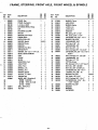
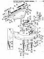
FRAME, STEERING, FRONT AXLE, FRONT WHEEL & SPINDLE “*- *
USE LOCKTITE “NUTLOCK” -
; . A Cee «A . mA TE т.
Оо ; Lu? Pra, RETOS o I
® "
. Coe. ld im = = - 1
* e A % vow x
5.
—
— od
REF PART | | = e
NO. NO. DESCRIPTION 8 8
a 029002 FRAME, Gear 1
… 529009 FRAME, Hydrostatic 1
2 029158 L.H. BALL JOINT 2 2
3 629007 STEERING WHEEL W/Cap 1 1
4 029163 CAP 1 1
5 0290020 = STEERING COLUMN 1 1
6 029023 SPACER 1 1
7 054025 - BEARING, Side Flange 1 1
8 029021 PINION GEAR 1 1
9 029133 . NEEDLE ROLLER 1 1
‘10° 064095 ~~ WASHER, Special 3(AR)3
11. 055076 BUSHING’ Nylon 11
12 055080 BUSHING 11
13 055083 BUSHING, Hex Воге 2 2
14 029017 ARM 8 SHAFT 11
15 064111 WASHER, 7/8 1.D.x 1-1/4” 0.0. 2 2
16 029019 BEVEL GEAR SEGMENT 1 1
17 028012 LINK 11
18 029010 - CRANK 1 1
19 029011 BLOCK 4 4
20 029007 MOUNTING, Front 1 1
21 029006 AXLE PIVOT 1 0
22 029005 AXLE, Front 1 ‘1
23 029008 - SPINDLE, LH. 1 1
24 029009 SPINDLE, R.H. 1 1
25 064109 WASHER, Special 4 4
26 067027 © COTTER, “T" Head 2 2
27 029173 GREASE CAP 2 2
629001 + WHEELASSY (Consistsof) 2 2
28 -— 055086 BUSHING 2 2
2 071099 TIRE, 15 x 6.00 1 -1
30. 071100 WHEEL 11
31 029171 ~~ BALL JOINT, R.H. 2 2
32 029016 — TIE ROD 2 2
-21-
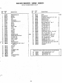
FRAME, STEERING, FRONT AXLE, FRONT WHEEL & SPINDLE
у сч
REF PART a s 8
; on
NO. NO. DESCRIPTION 3 €
33 075059 WASHER, Thrust 2 2
34 029013 LOCK STRIP 2 2
35 029024 WASHER, Spring 4 4
36 029015 LATCH, L.H. 1 1
37 029014 LATCH, R.H. 1 1
38 029018 - BRACKET 1 1
39 058004 PIN, Spring, 1/4" x 1-1/2" 1 1
40 067006 PIN, Cotter, 3/16” x 1-1/4" 2 2
41 059003 “CAPSCREW, HH, 5/16 -18x1 2 2
42 064002 WASHER, Flat, 5/16” 2 2
43 063003 LOCKWASHER, 5/16" 4 «4
44 065015 NUT, Hex, 5/16” - 18 4 4
45 063021 LOCKWASHER, 3/8" 13 13
46 065018 NUT, Hex, 3/8” - 16 7 1
47 1062005 BOLT, Carriage, 3/8" -16x 2-1/2" 4 4
48 059133 CAP SCREW, HH, 3/8” - 16x 1-1/4" 2 2
Grade 5
49 062012 BOLT, Carriage, 1/4" - 20 x 3/4” 1 1
50 063002 LOCKWASHER, 1/4" 1 1
51 065032 NUT, Hex, 1/4 - 20 1 1
52 022093 FITTING, Grease 2 2
53 058050 PIN, Grooved, 1/4" x 1-1/4 Type E 2 2
54 065005 NUT, Hex, 3/8" x 24 UNF, 6 6
55 065073 NUT, Hex, 3/8” -24 UNFLH. 2 2
56 059004 CAPSCREW, HH, 3/8” -16x 1” 3 3
57 065039 LOCKNUT, Hex, 3/8” - 16 2 2
58 064043 WASHER, Flat, 3/8” - 4(AR)4
59 067024 PIN, Cotter, 1/8" x 3/4" 2 2
60 062029 BOLT, Carriage, 3/8” - 16 x 1” 2 2
61 059128 CAPSCREW, HH, 5/16" -18x 2 2
п 1-3/4" Grade 5
° 62 064008 WASHER, Flat, 3/8" 3 3
63 064041 WASHER 1 1
64 064102 WASHER 1 1
059004 CAP SCREW 11
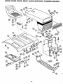
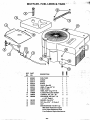
HOOD, REAR DECK, SEAT, DASH SUPPORT, RUNNING BOARD =
HOOD, REAR DECK, SEAT, DASH SUPPORT, RUNNING BOARD
. — y
REF PART 5 8
NO. NO. DESCRIPTION 8 8
1 529007 HOOD (Gear) 1
— 529008 HOOD (Hydro) 1
2 029124 GRILL INSERT 1 1
3 029122 HINGE, Hood 2 2
4 065095 NUT, Crown 5/16” - 18 2 2
5 029119 REAR DECK 1 1
6 075054 BUMPER, Rubber 2 2
7 1029134 REFLECTOR, Tail 1 1
: 8 029123 HINGE 2 2
9 029038 SPRING 2 2
10 029127 SEAT - ВЕ 1 1
11 029107 SUPPORT, Front 1 1
12 029106 SUPPORT, Rear 1 1
13 029120 CONSOLE, (Gear) 1
| 029121 CONSOLE (Hydrostatic) 1
14 029254 RUNNING BOARD, L.H. 1 1
15. 029253 RUNNING BOARD, R.H. 1 1
16 529006 — BASE (Gear) 1
17 529005 BASE (Hydro) | 1
18 - 075058 STOP (Pressure Sensitive Backing) — 2 2
19 064007 WASHER, Flat, 1/4” - 8 8
20 063002 LOCKWASHER, 1/4" 10 10
21 065032 NUT,Hex,1/4"-20 - 10 10
22 062029- BOLT, Carriage, 3/8"-.16x1" 6 6
23 061041 SCREW, Machine, 1/4" - 20x 5/8" 6 6
24 1064008 WASHER, Flat, 3/8" | 10 10
25 063021 LOCKWASHER, 3/8” 18 18
26 065018 NUT, Hex, 3/8" - 16°. 14 14
27 061045 SCREW, Machine, 5/16"- 18x 1/2” 2 2
28 064002 WASHER, Flat, 5/16" 14 14
29 063003 — LOCKWASHER, 5/16" 22 22
30 059022 CAP SCREW, HH, a
В 6/16" - 18 x 3/4” 6 6
31 065015 NUT, Hex, 5/16" - 18 16 16
32 059003 CAPSCREW, HH, 5/16”-18x1” 4 4
33 059135 CAP SCREW, HH, 5/16" x 18 x 3/4” |
Ш — Grade5 | 4 4
34 059004 CAP SCREW, HH, 3/8” - 16x1” 8 8
35 061042 SCREW, Machine, 5/16” -18x 3/4" 44
36 062011 "BOLT, Carriage, 5/16" - "18 x 3/4" 2 2
37 J-CLAMP - 1 4
— 69094
— 23.
ENGINE | у”
|, СВАМКЗНА!
RE
LACA
ETE
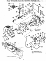
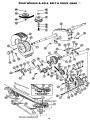
REAR WHEELS & AXLE, BELT & DRIVE-HYDROSTATIC: %:
Mis
”
© ,”" NOTE:USEPERMATEX |
— WHEN REPLACING
STATIONARY”
2 g i ; © IX
\\ - SPRING LOADED |
©
o \ ( A
NIN 3
а
sf 1
NN
TX L
7
o . =
* . —
NOTE: KEEP RESERVOIR (REF. NO. 24)
— HALF FULL WITH TYPE A TRANSMISSION
FLUID. В | —
"+
-
N
JIT;
Seit -
WO
"HYDROSTATIC TRANSMISSION DRIVE
`
\
А |
}
2
x 47.
49
; Nu
REF . PART =
ND. No. DESCRIPTION =
: 1 029265 IDLER ARM 1
2 055077 BEARING, Nylon 2
3 083111 SPRING | 1
4 073054 IDLER 1
5 010360 1 SPACER 1
6 029041 ' SHEAVE 1
7 . 029142 SPACER 1
8 029043 FAN 1
- 9 064093 = WASHER, Special 1
10. 029042 SHIELD 1
t11 629010 — DRIVE ASS'Y HYDROSTATIC 1
029044 GASKET 1
"a TRANSMISSION (Tecumseh No. 1
В — 1309) ;
629002 ‘WHEEL ASS'Y, Rear Consists of: 2
14 ; 071102 RIM 1
IS — 071101 TIRE, 20 x 8.00:10 1
16 029160 SPACER 1
072102 "V” BELT (Hydrostatic) | ВЕ
18 066018 KEY, Square, 1/4" x 1/4” х 1 3/4" 2
19 064029 WASHER, Special 2
20 067027 COTTER, “T* Head 2
21 029173 . CAP, Grease — 2
22 023077 “U” BOLT & CLAMP ASS'Y 2
23: 064002 WASHER, Flat, 5/16" 2
24 029045 RESERVOIR, Oil 1
25 029001 CAP 1
26 029138 CLIP 1
27 029135 : - HOSE 1
‚ 029046 SPUR GEAR 1
| “The transmission i is to be serviced and warrantied by Tecumseh Products.
t + Assembly includes Ref. No. 52 thru 62
-25-
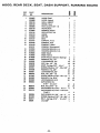
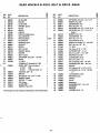
REAR WHEELS & AXLE, BELT & DRIVE -HYDROSTATIC
. сы
REF PART ©
NO. NO. DESCRIPTION S
29 029143 SPACER 1
30 057061 RING, Retaining 1
31 057092 CLAMP, Spring 1
32 069096 CLAMP, Spring 1
33 064110 WASHER 2
34 058016 ROLL PIN, 3/16” x 1” 1
35 059140 CAPSCREW, H.H. 5/16" - 18 x 1-1/2
Grade 5 1
36 063021 | LOCKWASHER, 3/8" 6
37 065042 LOCKNUT, 5/16" - 18 1
38 066006 KEY, Woodruff, No.3 2
39 059132 CAPSCREW, HH, 1/4” - 20 x 1 1
40 063002 — LOCKWASHER, 1/4” 1
41 070009 FLANGE WHIZLOCK SCREW 4
43 059141 CAP SCREW, HH, 3/8” - 16 x 3” Grade 5 4
44 059023 — CAP SCREW. HH 3/8” - 16 х 3/4” 2
45 029105 $НЕАМЕ 1
46 066026 KEY, Square, 1/4” x 1/4" x 2-1/2" 1
47 059142 CAP SCREW, HH. 7/16” -20 x 1” 1
48 063005 LOCKWASHER, 7/16" 1
064047 - WASHER, Special 1
50 029139 SPACER 1
51 065039 LOCKNUT, 3/8” - 16 1
52 029217 —- DUMP VALVE 1
53 029215 NUT, W/Gasket 1
54 056078 “0” RING 1
55 056079 OIL SEAL 1
56 029216 GASKET 1
57 029214 ADAPTOR 1
58 057072 “SNAP RING 1
59 054071 BEARING 1
60 056095 SEAL 1
61 529014 INPUT SHAFT W/BEARING & SNAP RING 1
62 054071 SNAP RING 1
63 012132 "IDLER 1
64 . 029264 PIVOT PIN 1
| - 064123 - WASHER 2
© CRANKSHAFT NON. 77
© REAR WHEELS & AXLE, BELT & DRIVE -GEAR %* ©
NSTATIONARY / NNN
© INTERMEDIATE SHAFT (46) о
o a DRIVE BELT S NIE < (3)
vA
| TRANSMISSION
DO {DRIVE
a BELT
IN x t . ; ' oo
> E - tw
MECHANICAL TRANSMISSION DRIVE
REAR WHEELS & AXLE, BELT & DRIVE -GEAR
REF PART | =
“no. NO. DESCRIPTION a
1 029028 IDLER ARM 1
2 029140 SPACER 2
… 3 ‘ 029029 IDLER ARM 1
4 064101 WASHER, Special 1
- 5 073101 IDLER 2
6 083110 SPRING 10
= 7. 073064 SHEAVE 1
8 629003 ~ SHEAVE W/Ball Bearing 1
9 054073 — BALLBEARING 2
10 064108. SPACER, Washer — —3
“11 029034 — IDLERPIVOT 1
12 055077 BEARING, Nylon 2
‘13 029035 - SUPPORT 2.
14 083117 SPRING 1
15 028039 BELT GUIDE 2
16 064102 1 WASHER, Special 4
17 064110 WASHER = 2
18 7029036 = BELTGUIDE = 1
19 059022 1 CAPSCREW, HH, 5/16" - 18 x 3/4” 1
20 029031 - STRAP 1
21 072100 * "V”BELT 1
*22 В TRANSAXLE’ Tecumseh No. 1212 A
© 629002 WHEEL ASS'Y, Rear, Consists of ©
2 ВЕ 071102. RIM A
A 071101 TIRE, 20 x 8.00 - 10 1
25 065039 LOCKNUT, 3/8” -16 1
26 029160. SPACER o 1
27 066018 KEY, Square, 1/4" x 1/4" x 1 3/4” 2.
28 064029 - WASHER, Special 2
29 067027 . COTTER, ”T” Head 2
“30 029173 ‚ САР, Сгеасе 2
- 31 023077 CLAMP ASS'Y 2
32 2
— 064002 -
— WASHER, Flat, 5/16"
"The Transaxle is to be serviced and warrantied by Tecu mseh Products
- 27 -
REF
(AR)
36
45
065042
PART ©
NO. NO. DESCRIPTION a
33 059005 CAP SCREW, HH, 3/8” - 16 x 1-1/4" 2
34 064008 WASHER, Flat, 3/8" 6
35 063021 LOCKWASHER, 3/8" 8
065018 NUT, Hex, 3/8” - 16 | 8
37 059143 CAP SCREW, HH, 1/2" x 2-1/4" Gr. 5 1
38 059058 CAP SCREW, HH, 1/2" - 13 x 3-1/4" 1
| | Grade 5
39 064120 WASHER, Flat, 1/2" 2
40 063006 LOCKWASHER, 1/2" 2
41 065021 NUT, Hex, 1/2” - 13 2
43 066003 KEY, Woodruff, No.9 1
44 060030 SCREW, Hex Socket, 1/4” - 20x 5/8" 2
065099 = NUT, Hex Jam, 1/4” - 20 Ш
46 072103 “V" BELT 1
47 067006 PIN, Cotter, 3/16" x 1-1/4" 1
48 059004 CAPSCREW,3/8”-16x1" 2
49 059158 BOLT, Tap, 3/8” 16x 1-3/4" 2
50 064002 WASHER, Flat, 5/16" 2
51 063003 —LOCKWASHER, 5/16” 2
52 065015 NUT, Hex, 5/16 -18 2
53 062011 = BOLT, Carriage, 5/16" - 18 x 3/4" 1
54 059023. CAP SCREW, HH, 3/8" - 16 x 3/4" 2
55 029105 SHEAVE | a 1
56 066026 KEY, Square, 1/4” x 1/4” x 2-1/2" 1
57 059142 CAP SCREW, HH, 7-1/16” - 20 UNF
| x1" 1
58 063005 LOCKWASHER, 7/16" 1
59 064047 WASHER, Special 1
60 029139 SPACER | 1
61 073054 IDLER 1.
62 029263 BRACKET 1
63 059069 - CAPSCREW 5/16” - 18x1- 1/4 1
64 075026 СВОММЕТ 2
65 064007 WASHER o 1
66 LOCKNUT 5/16” - 18 1
* SHIFT CONTROL & LINKAGE -HYDROSTATIC |
CREF PART ©
no. No. DESCRIPTION 2
1 029061 SHIFT LEVER 1
2 075049 HANDLE 1
3 083112 SPRING, Tension 1
4: 029055 PIVOT ASS'Y 1
5 029062 . BRACKET - 1
6 029057 LINK 1
7 029053 . NEUTRALIZER = 1
8 064117 SHIM, 005 Thick — 2
9. 064118 SHIM,O10 Thick 1
10 064119 ‘SHIM, 025 Thick (AR 4)
11 064108 SHIM, Washer (AR)
12 029064 ARM 1
13 029159 SPACER 2
147 029056 ° PLATE 2
15 055080 . BUSHING . 4
16. 029066 — ROLLER - 3
17 029065 SPACER 3
18 0290052 | САМ 1
19 029063 PLATE 1
.20 029060 LEVER 1°
21 029160 - WASHER, Spacer 1
22 029068 SPACER 1
.23 029054 LEVER 1
24 629033 FRONT DRAG BRKT. w/Lining 1
25 059004 CAPSCREW, HH, 3/8"- 16x 1" 4
26 629032 REAR DRAG BRKT. w/Lining 1
27 083115. . SPRING 1
- 29 -
SHIFT CONTROL & LINKAGE -HYDROSTATIC
RIVET
vu
REF PART ©
NO. №. DESCRIPTION 2
28 064009 WASHER, Flat, 3/4" 2
29 058019 PIN, Grooved, 3/16” x 1 Type E В
30 058049 PIN, Grooved, 3/16" x 1-1/4" a.
| = Type E 1
31 022093 FITTING, Grease, 1/4" - 28 1
32 059023 “CAPSCREW, HH, 3/8" -16x 3/4” 1
33 064008 WASHER, Flat, 3/8" 010
34 063021 LOCKWASHER, 3/8" 9
35 059003 CAPSCREW, HH, 5/16" - 18x 1" 2
36 064002 WASHER, Flat, 5/16" 4"
37 063003 LOCKWASHER, 5/16" 5
38 065015 NUT, Hex, 5/16” - 18 5
39 1067024 PIN, Cotter, 1/8" x 3/4” 1
40 059005 CAP SCREW, HH, 3/8" -16 x 1-1/4" 2
41 065018 NUT, Hex, 3/8" - 16 8
42 059073 CAP SCREW, HH, 5/16” - 18 x |
1-3/4" 1
43 066006 KEY, Woodruft, No. 3 1
44 059027 CAPSCREW, HH, 3/8" - 16x ВЕ
| 1-3/4" 1
45 065039 LOCKNUT, Hex, 3/8” - 16 2
46 062011 BOLT, Carriage, 5/16" - 18 x So
1-3/4" | 2
47 062030 BOLT, Carriage, 1/4" - 20 x 3-1/2" 1
48 064007 ~ WASHER, Flat, 1/4” 1
49 065070 LOCKNUT, Hex, 1/4" -20 1
50 029220 LINING 2
51 068053 40
- SHIFT CONTROL & LINKAGE «GEAR 15:5
CAP SCREW, HH, 5/16” - 18 x 2-3/4"
‚+30-
REF PART 8
~ NO. NO. DESCRIPTION 8
1 029047 LEVER ASSEMBLY EE
2 075049 HANDLE = 1
3 029048 CHANNEL 1
4 055078 . BUSHING, Nylon 4
5 083116 SPRING 1
“6 029049 ‘ROD 14
7 1029050 PIVOT À
8 029051 SPACER — 1
—9 029025 - SPACER, Bushing 1°
10 064104 — WAHSER, Special a 1
11 059003 CAP SCREW, HH, 5/16” - 18 x 1” 2
12 064002 ‘WASHER, Flat, 5/16” | 5
13 063003 LOCKWASHER, 5/16” 3
14 065015 NUT, Hex, 5/16" - 18 3
15 067021 PIN, Cotter, 1/8” х 1-1/2" 1
16 064121 WASHER, Flat, 7/16" 5
17 067004 PIN, Cotter, 1/8" x 1” 5
18 059074 1
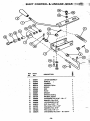
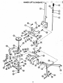
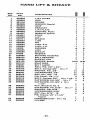
BRAKE & PARKING BRAKE
sl
REF PART | | Е 8 REF PART | S 82
° № NO. ~ DESCRIPTION a € NO. NO: DESCRIPTION = 3
1 0290667 BRAKEPEDAL 1 1 22 055089 BUSHING 1
2 055081 BEARING, Nylon 1 1 23 083117 SPRING 1 1
3. 075051 — PAD, Pedal 11 24 029144 SPACER BUSHING 1 1
4 029081 ‚ ARM "oo 25 067021 PIN, cotter, 1/8" x 1-1/2" 1 1
5 029076 ROD 1 1 26 067024 PIN, Cotter, 1/8" x 3/4” 4 3
6 029069 ARM —. 1 1 27 058049 PIN, Grooved, 3/16” x 1-1/4" TypeE1 1
7 0290728 ВЯАКЕ ВОО 1 1 28 063003 LOCKWASHER, 5/16" 11
8 "029079 SPACER | 1 1 29 064002 WASHER, Flat, 5/16" 2 2
© 9° 083113 SPRING, Compression 1 1 30 065015 NUT, Hex, 5/16" - 18 7 5
10 029070 BRAKE PIVOT (Gear) 1 31 067002 PIN, Cotter, 3/32" x 1” 11
~~ 029071 BRAKE PIVOT (Hydrostatic) 1 32 066003 KEY, Woodruff, No. 9 1 1
11 055024. BUSHING 1 1 33 060030 SCREW, Hex Socket, 1 1
© 12 - 029037 BRAKE DRUM 1 1 | 1/4" - 20 x 5/8" |
13: 29262 BRAKE BAND , W/Lining 11 34 065099 NUT, Hex Jam, 1/4” - 20 1 1
‚14. 062023 BOLT,Carriage 5/16” - 18x 1-1/2° 1 1 35 058019 PIN, Grooved, 3/16” x 1” TypeE 2 2
18. 0290722 ARM 0 1 1 — 36 059005 CAP SCREW, 3/8" - 16 x 1-1/4 1 1
@ 16 029073 - BRAKE LOCK 1.1 37 064008 WASHER, Flat, 3/8” 1 -
| 17.075052 KNOB 11 38 063021 LOCKWASHER, 3/8” 1
a 18 083109 SPRING 1 1 39 065018 NUT, Hex, 3/8” - 16 1
19 055077 BEARING, Nylon 2 2 |
20 029077 ROD 1
21. 029080 — ANGLE 1
- 31 -
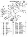
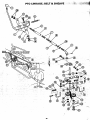
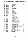
PTO LINKAGE; BELT & SHEAVE —
AN |
CRANKSHAFT > BELT GUIDE — ALL BELT GUIDES
Jf SHOULD HAVE 1/8” CLEARANCE
NS i 1DLER SLOTTED +
G Y -FQR ADJUSTMENT
Cc
- 32 -
PTO LINKAGE, BELT & SHEAVE
075055
- 33 -
| a 3 8
— REF PART S ©
NO. No. DESCRIPTION 8 &
1 029098 HANDLE 1 1
2 075052 KNOB 1 1
3 029104 PIN 1 1
4 029103 SPACER 1 1
5 064105 WASHER, Special 1 1
6 029102 GUIDE TUBE 1 1
7 083114 SPRING 1 1
“8 029097 ROD 1 1
9 083118 SPRING 11
10 029101 CLEVIS 1 1
11 055084 BUSHING 2 2
12 029100 SUPPORT 1 1
13 029099 - IDLER PIVOT 1.1
14 064100 WASHER, Special 1 1
15 073101 IDLER 2 2
16 029136 BELT FINGER 11
17. 029137 — BELT FINGER 2 2
18 072101 “V" BELT 1 1
19 067004 - PIN, Cotter, 1/8” x 1 3 3
20 059149 CAP SCREW, HH, 3/8" - 16
: x 2-1/4” Grade § 1 1
21 064008 WASHER, Flat, 3/8" BS
22 063021 LOCKWASHER, 3/8" 4 4
23 065018 NUT, Hex, 3/8" - 16 4 4
24 064007 WASHER, Flat, 1/4" 5 5
25 064002 WASHER, Flat, 5/16" 11
26 065015 NUT, Hex, 5/16” - 18 3 3
27 065061 NUT,Hex Jam, 5/16" - 18 1.1
28 067016 ~ PIN, Cotter, 5/32" x 1” 11
29 059068 CAPSCREW, HH, 3/8" -16x2" 1 1
30 64043 - WASHER, Fiat, 3/8” 2 2
31 062012 BOLT, Carriage, 1/4”- 20x 3/4" 4 4
32 063002 LOCKWASHER, 1/4" 4 4
33 065032 NUT, Hex, 1/4” - 20 4 . 4
34 059041 CAPSCREW,HH,1/2"-13x2-1/4"1 1
35 062006 BOLT, Carriage, 1/2” - 13x 2-1/2" 1 1
36 064120 WASHER, Flat, 1/2" 1-1
37 1063006 LOCKWASHER, 1/2” 1 1
38 065021 “ NUT, Hex, 1/2” 11
39 064094 J-CLAMP 1 1
- 40 064047 WASHER, Flat, 1/2" 2 2
41 065097 LOCKNUT, Hex, 1/27-13 1 1
… 4 062029 BOLT, Carriage, 3/8" - 16 x 1” 2 2
43 064102 WASHER, Special A 2 2
44 GROMMET 1 1
RE
as
Е E RIA 20 EEE TA Na UT > EA
E TO . . - End Seige nd a SE pad eo Ne sE fe Ree E ELENA ig
. > ; UT - CA PRAT CMA Mere Ll CR AOL TE WARN Le TL a TTR PT Su IS EL,
male =, ROT o . . TW es Ea TA comes AE UU Folie A E i eee Rg
De nll . — . Моя, von ° ‘В
HAND LIFT & SHEAVE
J-CLAMP
- 35 -
— eu
REF PART s 8
NO. No. DESCRIPTION = &
1 029082 LIFT LEVER 1 1
2 029083 ROD 1 1
3 083104 SPRING 1 1
4. 064096 WASHER, Special 1 1
. 5 075053 GRIP 1 1
6 029084 BRACKET 1 1
7 029090 LIFT PLATE 1 1
8 055082 BUSHING, Nylon 2 2
9 064097 WASHER, Special В 1
10 029091 STRIP 1 1
11 029088 LIFT 1 1
12 029141 SPACER 2 2
13 029092 LINK 11
14 029096 PIN 1 1
15 029093 — LINK, R.H. 1 1
16 029094 LINK, L.H. 1 1
-17- 55089 BUSHING 8 8
18 029095 LINK 2 2
19 029085 SHEAVE 1.1
20 64088 WASHER 2 2
21 029089 BEARING HOUSING t 1
22 054073 BALL BEARING 2 2
23 1029086: SHEAVE,PTO 1
24 064108 WASHER, Special (AR) (AR)
25 057012 SNAP RING 11
26 029087 BELT GUIDE 1 1
27 058034 - ROLL PIN, 1/8” x 3/4" 1 1
28 062029 BOLT, Carriage 3/8” - 16 x 1” 4 4
29 064008 WASHER, Flat, 3/8" 14 14
30 063021 LOCKWASHER, 3/8" 14 14
31. 065018 NUT, Hex, 3/8" - 16 14 14
32 1067004 PIN, Cotter, 1/8” x 1" 6 6
33 062016 BOLT, Carriage, 3/8” - 16 x 1-1/4" 2 2
34 059004 CAPSCREW, HH, 3/8” - 16x1” - 4 4
35 059005 CAP SCREW, HH, 3/8” x 16x ~~
RE 1-1/4" 4 4
36 066003 KEY, Woodruff, No. 9 1 1
37 059003 CAP SCREW, HH, 5/16” - 18х 1" 2 2
38 064002 WASHER, Fiat,5/16" 3 3
— 39 063003 LOCKWASHER, 5/16” 3 3
40 065015 _ NUT, Hex, 5/16” - 18 2 2
41 058050 PIN, Groove, 1/4" x 1-1/4" | |
| Туре Е | 1 1
42 059039 CAPSCREWS5/16"-18 x 1/2 1 1
43 069094 1 1
DASH CONTROLS &
TO MAGNETO.”
~ GROUND .
TO CENTER
Cr mi py me AR р
DASH, DASH CONTROLS & ELECTRICAL
о _ | _ ENGINE -
m “e N a | — Td RECTIFIER = 7% AMP FUSE & CONNECTOR
р \ [- Y _
FH STATOR \ | RED TT Г
\ | BLACK ’ !
| / — | -7
A.C. CONNECTOR |
© piack MAGNETO SPARKPLUG | | | $
NT od | р» IMPLEMENT CLUTCH BATTERY
: | NEUTRAL SWITCH =
Lo — я
| | le GEAR SHIFT OR J
| HYDROSTATIC CONTROL .
WHITE LEVER NEUTRAL SWITCH =
MICRO SWITCH | `
gr IR AS [starten
| 15) k= - |
| | BLACK
18 | Y
12 | | IGNITION SWITCH ¥
NM | Leumee — 71
ix ` -
| } LIGHT SWITCH
NE
8 |
© emeurt i [ S-8 GARDEN TRACTOR WIRING DIAGRAM |
BREAKER Lor —— HE
~~ ЧЕ BLACK | STANDARD EQUIPMENT
ВЕ i 77 ; ; о
| OPTIONAL EQUIPMENT
| Ne o]
| HEAD LIGHTS JE 1% | wr
| | 7 e |= Lal RSE HT ra LIGHT
и { A x iJ
Ne Вл | : CONNECTORS, (
=
REF PART © о Ss 8 REF PART е ©
В _ | N
NO. NO. | DESCRIPTION Ss y NO. NO. DESCRIPTIO S $
1. 029175 BATTERY, 12 Volt 11 23 075057 INSULATOR 11
2 029026 - CABLE 3 3 24 029164 WIRE 1 1
3 029132 SOLENOID — 1 1 25 029168 WIRE 14” long, White 1 1
| 4 029149 SWITCH, Ignition 1 1 26 059022 CAP SCREW, 5/16” - 18 x 3/4" 1 1
. 5 013157 KEY SET 1 1 27 059001 CAP SCREW, HH, 1/4” - 20 x 3/4" 4 4
—e 065106 . NUT, Special, 9/16” - 24 1 1 28 063003 LOCKWASHER, 5/16” 3 1
7 . 029167 ‘WIRE ASS'Y, 29” long Black 11 29 063002 LOCKWASHER, 1/4” 4 4
a 8 029169 — WIRE ASS'Y, 24” long, Yellow 1 1 30 065015 NUT, Hex, 5/16" - 18 3 1
: 9 | 029170 = ~ CONNECTOR HOUSING, 2 Wire .2 2 31 065032 NUT, Hex, 1/4” - 20 4 4
‘ 10 029131 SWITCH, Safety 2 2 32 064007 . WASHER, Flat, 1/4” 2 2
ON 065096 ~~ NUT, Special, 9/16” - 18 UNF 2 2 33 074040 — SCREW, Self Tapping 5/16” х 1/2” 1 1
12 069094 ——— CLIP | 91 34 ‚ 064002 - WASHER, Flat, 5/16" 3 1
13. 075055 oo GROMMET 2 2 35 074043. ~ SCREW, Self Tapping, RH,
14 029166" WIRE HARNESS (Mechanical) 1 10-29 x 1/2" 5 5
15 029165 WIRE HARNESS (Hydrostatic) 0 36 064001 “WASHER, 3/16" Wrought 2 2
16 529003 - DASH W/Decal 11 37 063011 LOCKWASHER, No. 10 2 2
17 069094 JCLAMP . 1 38 065055 NUT, Hex, No. 10 - 24 2 2
18 069095 THROTTLE CONTROL 10 39 064123 WASHER, Flat, 5/16” 2 2
— 19 075019 KNOB 1.1 40 065095 LOCKNUT, Hex, 5/16” - 18 2 2
20 029128 ROD, Battery Hold Down 1.1 41 059003 CAP SCREW, HH, 5/16" -18x1" 2
21 029128 BRACKET, Safety Sw. 1 42 013198 FUSE 1 1
22 7029130 ACTUATOR, Safety Sw. 1 43 023478 CONNECTOR HOUSING 11
- 37 -
A R OT ARY M OWE R 36 R M В 29001 : A
SERIAL NUMBER 000301 ANO UP
REF PART o
NO.
_No.
ROTARY MOWER - 36RM - 829001
SERIAL NUMBER 000301 AND UP
DESCRIPTION
o
DON OH SM
PI P
—
25
26 -
27.
30
31
32
ео = осо сл $» бо по —
—
<
No
No
e
| 2.
029146
— 029153
-- 029176:
“029152
063011
073059
083117
083127
029151
“073054
“072077 —
073083 =
- 029154
- 0310446 ———
— “064048
“031144
054120 ——
x “029156 —
“020185 —-
031191...
059153 В
031141
. 028150
031156 —
.629019
055089
075069 ——
-— 029178
-— 067029
“ 072078
MOWER DECK, 36" _
SHIELD
SUPPORT
LINK
IDLER ARM
LOCKWASHER, No. 10
IDLER
- SPRING
— IDLER ARM Ea EE
_ y BELT Le
— SHEAVE >
SHEAVE
FLANGE
~~ WASHER, Special
- SPACER, Split (445 Thick)
BEARING, Ball
— SHAFT, Outside
SHAFT, Center
BLADE —
~ WASHER, Special |
CAPSCREW, Hex 7/16" - 20 x 1"
UNF Gr. 5
ROLLER
© SHAFT
LINK 7
© ADJUSTER, Roller
BUSHING -
"GRIP -
- PIN ©
© HAIRPIN COTTER -
"V” BELT
. REF
(AR)
NO.
“az
* 34
25
36
37
38
39
40
41
42
43
45
46
47
43
49
50
51
52°
53
; 55
56
PART
NO.
029177
729004
074046 —
— 064007 -
— 064039
067004
062029
064008
063021
065018
063006
065021
064003
059005
065001
062016
063027
065016
066083:
064140
059004
059156
065055.
064108
— DESCRIPTION —.
SHIM
MULCHER KIT
SCREW, Self Tapping H.H. 1/4” X 1"
WASHER, Flat, 1/4" |
WASHER, Special
PIN, Cotter, 1/8" x 1”
~ BOLT, Carriage, 3/8" -
6x1.
WASHER, Flat, 3/8"
“ LOCKWASHER, 3/8"
NUT, Hex, 3/8" - 16
LOCKWASHER, 1/27
NUT, Hex, 1/2 +13
WASHER, Flat, 1/2"
CAP SCREW, H.H. ur 16% 1; ve
NUT, Hex; Ja, 3/8" - -
BOLT, Carriage, 3/8" - 16x 1-1/4
— LOCKWASHER, Int, Tooth 3/4”
- NUT, Hex, Jam, 3/4” - 16 UNF
KEY, Woodruff, No.9
WASHER, Flat, 5/8"
CAPSCREW, HH. 3/8" - 16% 1”
CAP SCREW, Socket Hd. No. 10- 24 x 3/8"
~ NUT, Hex, No. 10 - 24
WASHER
9 (AR)
NOY OD
жа == — at
O o OO 6
ELL WN =
*Mulcher Kit Consists of Mulcher Plate and the Following Hardware:
062035
063021
065018
60
_ BOLT CARRIAGE, 3/8" x 3/4"
— LOCKWASHER, за
NUT, Hex, 3/8" -
2
2
- 39 -
Cm ._.REF PART a | S ©
CU No we, DESCRIPTION S 8
2 029162 FUEL TANK 1 1
3 029110 GUAGE 1 1
4, 029114 BRACE 1 1
—5 029115 STRAP | 1 1
‚ .6 031536 VALVE, Shut-Off | 1 1
| -7 - 029113 HOSE, 4” long, 1/4” 1D... 1 1.
8 029108 FUEL FILTER — 1-17
9 029112 HOSE, 8-3/4" long, 1/4” ID 1.1
10 070008 FLANGE WHIZLOCKSCREW * 4 4°
11 065070 LOCKNUT, Hex, 1/4” - 20 2 2:
12 059140 CAP SCREW, HH, 5/16” - 18 3
x 1-1/2" Grade 5 — 4 4
13 064123 WASHER, Flat, 5/16” 4 4
15 065124 NUT, Hex, 5/16” - 18 Grade C 4 4
16 029172 CLIP a 4 4 ~~
17 ENGINE BRIGGS *191707 Type 1 1
0636 Order Replacement Engine
and or Engine Replacement Parts
From Respective Engine Manufacturer.
- 40 -
me a REL PAE E
DEALER SET UP AND PRE-SERVICE INSTRUCTIONS
INSTALL ROLL PIN
_ Figure 42
STEERING WHEEL
Install the steering wheel on the column and secure with a
roll pin as shown in Figure 42.
— SERVICE BATTERY
| Remove the battery from the tractor. This will prevent
any accidentally spilled electrolyte from damaging the tractor.
| Electrolyte is not furnished with the tractor. Use only
-— + battery grade sulphuric acid electrolyte with 1.265 specific
gravity plus or minus 0.005 corrected to 80° F.
Prepare battery as follows:
1. Remove vent plugs.
POSITIVE (+)
ona gD
| NN
AE —) TERMINAL
GROUND CABLE
A 7
holo BoM Y BRACKET
| НО
Figure 43
- 41 -
2. With battery removed from the tractor, fill each cell
with electrolyte until electrolyte level rises to split ring at
the bottom of the filler tube. DO NOT OVERFILL.
BE CAREFUL! ELECTROLYTE CONTAINS SUL-
PHURIC ACID WHICH IS HARMFUL TO SKIN,
EYES AND CLOTHING. HANDLE WITH EX-
TREME CARE. IF SPILLAGE OCCURS ON BODY
OR CLOTHING, RINSE AT ONCE WITH WATER.
3. After filling cells, wait five to ten minutes and add
additional electrolyte if necessary to bring electrolyte to
proper level.
4. Charge battery with a 12 volt charger for 30 minutes at
4 to 6. amps. |
5. After charging, add electrolyte until the level is up to the
split ring in the filler tube. Thereafter, add only clean, dis-
tilled water as use and time requires.
6. Replace vent caps. Clean and dry battery exterior.
INSTALL BATTERY
Place the battery in the battery carrier as shown in
Figure 43 with the positive (+) terminal to the right side of the
tractor,
Secure the battery in place with the battery hold down as
shown in Figure 43. Do not overtighten the hold-down nuts.
Attach the battery cable to the positive (+) terminal and
the ground cable to the negative (-) terminal as shown in
Figure 43. Tighten the cables to the terminals securely.
Coat the terminals and the battery cable ends with a light
coat of grease or petroleum jelly to prevent corrosion.
ENGINE OIL
- Fill the engine crankcase (Figure 44). Use Ariens Gard-N-
Yard MS 10W-30 oil when using lawn and garden attachments,
use Ariens Sno-Thro oil {SAE 5W - 20 MS classification) when
using snow removal attachments.
Do not overfill - the oil level must never exceed the full
mark.
TRANSMISSION OIL LEVEL (gear shift model 929001)
Check the oil level using the following procedure:
1. Place tractor on a level surface.
2. Raise rear deck to gain access to the transmission check
level plug.
3. Remove check plug, Figure 45. Oil should seep out of the
check plug hole. If the level is too low, remove the filler
ENGINE E DIP STIC
FA ai
Cum
Figure 44
plug and add Ariens MP-90 Premium Gear Lube (SAE
90-EP) weight transmission oil until the level is correct.
— 4. Replace both the filler and the check plugs.
CAUTION: THE HYDROSTATIC TRANSMISSION
AND THE DIFFERENTIAL ASSEMBLIES HAVE
SEPARATE OIL RESERVOIRS. TYPE A TRANS-
MISSION FLUID MUST BE USED IN THE HY-
DROSTATIC TRANSMISSION AND ARIENS MP
:90 PREMIUM GEAR LUBE (SAE 90-EP} MUST
BE USED IN THE DIFFERENTIAL. IF IMPROPER
OIL IS USED IN EITHER RESERVOIR, SERIOUS
DAMAGE COULD OCCUR.
“TRANSMISSION OIL LEVEL (hydrostatic models) |
a — Check hydrostatic oi! level using the following procedure:
A. Place tractor on a level surface.
| 2. Raise the rear deck and remove the oil filler cap shown in
Figure 4 46.
o CAUTION: THE AREA AROUND THE FILLER
| .. CAP MUST BE CLEAN BEFORE REMOVING THE
| CAP. DO NOT ALLOW ANY DIRT OR FOREIGN
MATERIAL TO ENTER THE EXPANSION RES-
ERVOIR.
3. Check oil level. The expansion reservoir should be % full
at ambient temperature. If required, add type À trans-
mission fluid UNTIL THE RESERVOIR IS % FULL.
| CAUTION: If overfilled, the oil will expand during
AUN operation and may leak out around the filler cap.
If oil cannot be seen in the expansion reservoir, it will be
necessary to fill the reservoir to the proper level and bleed
(remove air) from the transmission. See Owner's manual for
this procedure.
- 42 -
Figure 45
Figure46
DIFFERENTIAL OIL LEVEL (hydrostatic models)
Check the differential oil level on hydrostatic tractors using
the following procedu re: о
1. Place tractor on a level surface.
2. Remove the oil level and filler plug from the rear of the
transmission, Figure 47. | |
3. Oil should reach the level and filler plug hole. If it does
not, add Ariens Premium Gear Lube MP-90 (SAE 90-
until the proper level is reached.
N
. Raise the tractor attachment lift lever.
3. Place cutting height adjustment lever in the second lowest
cutting position as shown in Figure 48.
4. Raise front support bar to clear the front tractor tire and
slide the mower under the tractor from the right side.
5. Place the drive belt over the rear lift point and lower the
attachment lift lever. Align ball joint of rear lift point to
tractor lift arms and secure with the ‘’L’’ shape attaching
pin and hairpin cotter provided. See Figure 48.
но 6. Position drive belt over th i
e drive and driven sheaves and
FILLER AND OIL LEVEL PLUG ON, place idler to the inside of the belt as shown in Figure 48.
HYDROSTATIC DIFFERENTIAL
Figure 47 7. Position front support bar in the tractor saddle brackets
FILL FUEL TANK
and secure with the locks and latches as shown in Figure 49.
Fill fuel tank with clean, fresh, regular grade gasoline. Do
not use premium gasoline,
ADJUST TIRE PRESSURE
— Tires are over-inflated for shipping purposes. Correct tire
pressures- are essential for proper handling or attachment
performance. Adjust tire pressures as shown in the chart. Use
alow pressure gauge for accurate readings.
[DESCRIPTION | LAWN | SNOW THROWER AND
| | WORK FRONT BLADE WORK SADDLE BRACKET N
— - Г (J vn SZ
Front tires (15 x 6.00-6) | 10 12 IAS FRONT SUPPORT BARZZ
[Rear tires (20 x 8.00-10)1 6 6 TI - |
TU AI 27H Figure 49
ASSEMBLE MOWER
TT ADJUST BLADE LEVEL AND PITCH
IMPORTANT: ADJUST MOWER BLADE LEVEL
AND PITCH AS OUTLINED IN THE OWNERS
MANUAL.
1. Remove shipping straps from front support bar and belt
idler. a |
"ATTACH MOWER TO THE TRACTOR
DELIVERY
Using the Owner's Manual as a guide, instruct the customer
as follows:
Use the following procedure to attach the mower to the
tractor: | |
0 Remove ignition key. Place implement power clutch lever
in the disengaged position and engage the tractor brake
lock. 1. Instruct the customer on the operation of the tractor.
a. Emphasize safety and discuss the safety information in
PE A” the Owner's Manual.
Ea ¡MPLEMENT POWER CLUTCH |
ST ‹ 2. Advise customer to change oil in the engine crankcase
after the first five hours of operation.
CUTTING HEIGHT
ADJUSTMENT LEVER,
a
3. Advise customer to change the transmission oil filter after
the first five hours operation.
| NOR |
HIGHEST = | 4. Explain how to perform the recommended lubrication
CUTTING Zag | Mm. and periodic service.
- POSITIO ia 1)
NN
\ 5. Explain maintenance and adjustment instructions.
MOSS: 6. Demonstrate how to mount and dismount attachments.
уз <X ARFRONT SUPPORT BAR
LOWEST” NL” SHAPED ON
ATTACHING PIN NTRACTOR LIFT ARMS
CUTTING AND HAIR PIN
POSITION COTTER
7. Make certain the customer has his Owner's Manual.
Figure 48 8. Explain Ariens Warranty Policy. Fill out and return Ariens
| Warranty Registration Card.
- 43 -