1
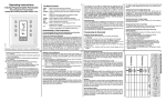
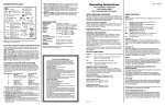
8532
Cool Only Thermostat
OPERATING INSTRUCTIONS
Your new digital thermostat has been designed to provide accurate control and display of room temperature.
In addition, it also will display all relevant information
pertaining to your system.
The clearly marked buttons and informative display
make it extremely easy to understand and simple to
use.
111-138B
Please take a few moments to read the brief instructions and familiarize yourself with the various functions
in order to obtain maximum benefit from this truly
unique electronic control.
j
GENERAL INFORMATION
The thermostat normally displays room temperature,
mode of operation and whether cooling is currently on.
The six buttons on the front of the unit allow complete
control of the equipment.
Raising or lowering the setpoints in cooling is as simple
as pushing a button. In addition, you may choose to
display the temperature in °F or °C.
The thermostat also allows you to select continuous fan
operation (useful when using an air cleaner) or have the
fan come on with the equipment.
USER CONTROLS
INSTALLER NOTES
MODE
Select the desired mode of operation by pressing the
MODE button repeatedly:
☛
– controls cooling system only (the word COOL is
displayed for 5 seconds).
OFF – The word OFF is displayed and the equipment
will not operate.
COOLING ☛
Select the temperature you want your equipment to
maintain while in the cooling mode by pressing and
holding the ✞ or ✟ buttons. The temperature setpoint
is displayed for 5 seconds.
FAN %
The fan will come on automatically when the system
is operating, but there is no indication of this on the
display. To select continuous fan operation, press the
FAN button and the display will show %. This is
recommended for electronic air cleaners or continuous ventilation requirements.
This page intentionally left blank.
SEE REVERSE FOR INSTALLATION INSTRUCTIONS
USER CONTROLS (Cont’d)
USER CONTROLS (Cont’d)
OUTDOOR (ODT) BUTTON
When the outdoor temperature sensor option is
connected to your thermostat, you can display the
current outdoor temperature by pressing the OUTDOOR button. If the option is not connected, the
thermostat will display – –✜.
LIMITED OVERRIDE
DAY/NIGHT BUTTON
When the thermostat initially is installed, the display will show the ✥ symbol for your day temperature. By pressing the DAY/NIGHT button or
closing the CLK1 and CLK2 terminals on the back
of the thermostat you may select an alternate or
night ✠ temperature. (The thermostat will remember this setpoint.) Simply press the DAY/NIGHT
button to alternate between temperature settings.
CELSIUS / FAHRENHEIT
Simultaneously press ✞ and ✟ to switch between
°F and °C temperature display.
When the keyboard is locked (switch #2 ON), the user
may override the temperature setpoint for 1 hour by
pressing either the ✞ or ✟ button. The range of temperature override is ±3°F or ±3°C from the programmed
daytime setpoint.
CLOCK TERMINALS (OPTION)
CLK1 – CLK2
Your thermostat is equipped with remote clock terminals. By connecting a remote clock/timer (DSP-AT
or equivalent) the thermostat can alternate between
the day and night setpoints automatically.
REMOTE SENSOR (OPTION)
RS1 – RS2 – RS+V
The thermostat is designed to accept the electronic
remote sensor, which will allow you to locate your
thermostat in an area away from view. Indoor and
outdoor sensors are available separately.
POWER FAILURES
Your thermostat employs the latest developments in
solid state electronic technology.
One of the unique features of your thermostat is that
no battery is required to maintain your selected setpoints in the event of a power loss as the memory is
unaffected by power failures of any duration.
When power is restored, the thermostat will continue
operating as if the power had never been off.
TEMPERATURE ACCURACY
Full temperature accuracy will be realized only after
the thermostat has been installed and powered for at
least one hour.
Model 8532
111-138B
97185
ELECTRONIC PROGRAMMABLE THERMOSTAT
TWO YEAR LIMITED WARRANTY
Your Research Products Corporation AprilaireTM Thermostat unit is
expressly warranted for two (2) years from the date of installation to be
free from defects.
Research Products Corporation’s exclusive obligation under this warranty shall be to supply, without charge, a replacement for any thermostat which is found to be defective within a two (2) year period and
which is returned no later than thirty (30) days after said two (2) year
period by you to either your original supplier or to Research Products
Corporation, Madison, Wisconsin, 53701, together with the model number, manufacturing code number and installation date of the thermostat.
THIS WARRANTY SHALL NOT OBLIGATE RESEARCH PRODUCTS CORPORATION FOR ANY LABOR COSTS AND SHALL NOT APPLY TO DEFECTS IN
WORKMANSHIP OR MATERIALS FURNISHED BY YOUR INSTALLER AS CONTRASTED TO DEFECTS IN THE THERMOSTAT ITSELF.
IMPLIED WARRANTIES OF MERCHANTABILITY OR FITNESS FOR A PARTICULAR PURPOSE SHALL BE LIMITED IN DURATION TO THE AFORESAID TWO
(2) YEAR PERIOD. RESEARCH PRODUCTS CORPORATION’S LIABILITY FOR
INCIDENTAL OR CONSEQUENTIAL DAMAGES, OTHER THAN DAMAGES FOR
PERSONAL INJURIES, RESULTING FROM ANY BREACH OF THE AFORESAID
IMPLIED WARRANTIES OR THE ABOVE LIMITED WARRANTY IS EXPRESSLY
EXCLUDED. THIS LIMITED WARRANTY IS VOID IF DEFECT(S) RESULT FROM
FAILURE TO HAVE THIS UNIT INSTALLED BY A QUALIFIED HEATING AND
AIR CONDITIONING CONTRACTOR. IF THE LIMITED WARRANTY IS VOID
DUE TO FAILURE TO USE A QUALIFIED CONTRACTOR, ALL DISCLAIMERS
OF IMPLIED WARRANTIES SHALL BE EFFECTIVE UPON INSTALLATION.
Some states do not allow limitations on how long an implied warranty
lasts or the exclusion or limitation of incidental or consequential damages so the above exclusion or limitations may not apply to you.
This warranty gives you specific legal rights and you may also have
other rights which vary from state to state.
This equipment if installed in strict accordance with the manufacturers
instructions,complies with the limits for a Class B computing device
pursuant to Subpart J of Part 15 of FCC rules.
INSTALLATION INSTRUCTIONS
THERMOSTAT INSTALLATION
LOCATION
To ensure proper operation, the thermostat should be
mounted on an inside wall in a frequently occupied
area of the building. In addition, its position must be
at least 18" (46cm) from any outside wall, and approximately 5' (1.5m) above the floor in a location with
freely circulating air of an average temperature.
BE SURE TO AVOID THE FOLLOWING LOCATIONS:
- behind doors or in corners where freely circulating
air is unavailable
- where direct sunlight or radiant heat from appliances might affect control operation
- on an outside wall
- adjacent to, or in line with, conditioned air discharge grilles, stairwells, or outside doors
- where its operation may be affected by steam or
water pipes or warm air stacks in an adjacent partition space, or by an unheated/uncooled area
behind the thermostat
- where its operation will be affected by the supply
air of an adjacent unit
- near sources of electrical interference such as arcing relay contacts
1. Insert a flat blade screwdriver or coin 1/8" into the slot
located in the bottom center of the thermostat case and
twist 1/4 turn. When you feel or hear a click, grasp the
case from the bottom two corners and separate from
the subbase as shown in the diagram at the right. Some
models require more force than others when separating
due to the number of terminals on the subbase.
2. Swing the thermostat out from the bottom.
3. Lift the thermostat up and off the subbase.
4. Place the rectangular opening in the subbase over the
equipment control wires protruding from the wall and,
using the subbase as a template, mark the location of
the two mounting holes (exact vertical mounting is necessary only for appearance).
5. Use the supplied anchors and screws for mounting on
drywall or plaster; drill two 3/16" (5mm) diameter holes
at the marked locations; use a hammer to tap the nylon
anchors in flush to the wall surface and fasten subbase
using the supplied screws. (Do not overtighten!)
6. Connect the wires from your system to the thermostat
terminals as shown in the wiring diagrams. Carefully
dress the wires so that any excess is pushed back into
the wall cavity or junction box. Ensure that the wires are
flush to the plastic subbase. The access hole should be
sealed or stuffed to prevent drafts from affecting the
thermostat.
SLIDE SWITCH SETTINGS
REPLACING THE THERMOSTAT
ON THE SUBBASE
1. Position the thermostat on the hinged tabs located at
the top of the subbase.
2. Gently swing the thermostat down and press on the
bottom center edge until it snaps in place.
OFF
Rated Voltage
20-30 VAC, 24 nominal
Rated
Current
0.08 Amps to 1.5 Amps
continuous per output with
surges to 4 Amps Maximum.
Control
Range
Cooling: 60° to 108°F in 1° Steps
16° to 40°C in 1° Steps
Thermostat
Measurement
Range
28° to 124°F or 0° to 48°C
O.D.T.
Display
Range
-50° to 124°F or -48° to 48°C
Control
Accuracy
±.5°C at 20°C
±1°F at 68°F
2 MINUTE
(MIN ON/OFF)
4 MINUTE
(MIN ON/OFF)
KEYBOARD
LOCKED
KEYBOARD
UNLOCKED
SPECIFICATIONS
ON
OUTPUT TERMINAL FUNCTIONS
RC . . . . .24 VAC supply from cooling equipment
Y . . . . . .Cooling energized on a call for cooling
G . . . . . .Fan energized
RS2
RS1
RS+V
CLK1 . .Use with remote clock/timer
CLK2
for alternate setpoints
RS2 . . . .For outdoor temperature sensor
RS1
and/or indoor remote sensor options.
RS+V
Refer to the instructions included with
the sensors.
8532
RC
Y
G
CLK1
CLK2
Line
Voltage
Y
G
24 VAC
Transformer
NOTE: This thermostat contains electronic circuitry
replacing the conventional mechanical anticipator.
P.O. BOX 1467 • MADISON, WI 53701-1467
CALL 608/257-8801 • FAX 608/257-4357
Products For Better Indoor Air Quality.