1
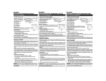
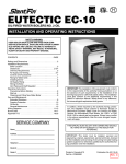
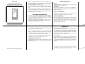
DSL-100
Heat Only Thermostat
OPERATING INSTRUCTIONS
Your new digital thermostat has been designed to
provide accurate control and display of room temperature. In addition, it will also display all relevant information pertaining to your system.
The clearly marked buttons and informative display
make it extremely easy to understand and simple to
use.
Please take a few moments to read the brief instructions and familiarize yourself with the various functions in order to obtain maximum benefit from this
truly unique electronic control.
GENERAL INFORMATION
The thermostat normally displays room temperature,
mode of operation and whether heating is currently
on. The two buttons on the front of the unit allow
complete control of the equipment.
111-123
Raising or lowering the setpoints in heating is as simple as pushing a button. In addition, you may choose
to display the temperature in °F or °C.
USER CONTROLS
MODE
The DSL-100 thermostat is a heat only control and is
permanently in the heat mode.
HEATING "
Select the temperature you want your equipment to
maintain while in the heating mode by pressing either
the ✞ or ✟ buttons.
CELSIUS / FAHRENHEIT
Simultaneously press ✞ or ✟ to switch between
Celsius and Fahrenheit temperature display.
LIMITED OVERRIDE
When the keyboard is locked (switch #2 ON), the user
may override the temperature setpoint for 1 hour by
pressing either the ✞ or ✟ button. The range of temperature override is ±6°F or ±3°C from the programmed daytime setpoint.
SEE REVERSE FOR
INSTALLATION INSTRUCTIONS
This page intentionally left blank
POWER FAILURES
WARRANTY
Your thermostat employs the latest developments in
solid state electronic technology.
LIMITED TWO YEAR WARRANTY
The manufacturer warrants to the original purchaser
that its product and component parts will be free
from defects in workmanship and materials for a period of two years from the date of purchase. Your dealer will provide free replacement of your DSL
thermostat upon proof of purchase.
One of the unique features of your thermostat is that
there is no battery required to maintain your selected
setpoints in the event of a power loss as the memory
is unaffected by power failures of any duration.
When power is restored, the thermostat will continue
operating as if the power had never been off.
TEMPERATURE ACCURACY
Full temperature accuracy will be realized only after
the thermostat has been installed and powered for at
least one hour.
INSTALLER NOTES
EXCLUSIONS
This warranty does not apply in the event of misuse,
abuse or as a result of unauthorized alterations or
repairs. The manufacturer will not be liable for any
consequential damages including, without limitation,
damages resulting from defects, loss of use, or
misuse.
This equipment, if installed in strict accordance with the manufacturer's instructions, complies with the limits for a Class B computing
device pursuant to Subpart J of Part 15 of FCC rules.
This page intentionally left blank
INSTALLER NOTES
This page intentionally left blank
Model DSL-100
111-123
97041
INSTALLATION INSTRUCTIONS
THERMOSTAT INSTALLATION
LOCATION
To ensure proper operation, the thermostat should be
mounted on an inside wall in a frequently occupied
area of the building. In addition, its position must be
at least 18" (46cm) from any outside wall, and approximately 5' (1.5m) above the floor in a location with
freely circulating air of an average temperature.
BE SURE TO AVOID THE FOLLOWING LOCATIONS:
- behind doors or in corners where freely circulating
air is unavailable
- where direct sunlight or radiant heat from appliances might affect control operation
- on an outside wall
- adjacent to, or in line with, conditioned air discharge grilles, stairwells, or outside doors
- where its operation may be affected by steam or
water pipes or warm air stacks in an adjacent partition space, or by an unheated/uncooled area
behind the thermostat
- where its operation will be affected by the supply
air of an adjacent unit
- near sources of electrical interference such as arcing relay contacts
1. Insert a flat blade screwdriver or a coin 1/8" into
the slot located in the bottom center of the thermostat case and twist 1/4 turn. When you feel or hear
a “click,” grasp the case from the bottom two corners and separate from the subbase as shown in
the diagram at the right. Some models require more
force than others when separating due to the number of
terminals on the subbase.
2. Swing the thermostat out from the bottom.
3. Lift the thermostat up and off the subbase.
4. Place the rectangular opening in the subbase over
the equipment control wires protruding from the
wall and, using the subbase as a template, mark
the location of the two mounting holes (exact vertical mounting is necessary only for appearance).
5. Use the supplied anchors and screws for mounting
on drywall or plaster; drill two 3/16" (5mm) diameter holes at the marked locations; use a hammer to
tap the nylon anchors in flush to the wall surface
and fasten subbase using the supplied screws. (Do
not overtighten!)
6. Connect the wires from your system to the thermostat terminals as shown in the wiring diagrams.
Carefully dress the wires so that any excess is
pushed back into the wall cavity or junction box.
Ensure that the wires are flush to the plastic subbase.
The access hole should be sealed or stuffed to prevent drafts from the wall affecting the thermostat.
➛ OFF
REPLACING THE THERMOSTAT
ON THE SUBBASE
1. Position the thermostat on the hinged tabs located at
the top of the subbase.
4 MINUTE
(MIN ON/OFF)
20-30 VAC, 24 nominal
Rated
Current
Max.
0.08 Amps to 1.5 Amps continuous
per output with surges to 4 Amps
Control
Range
Heating: 38° to 88°F in 1° Steps
5° to 30°C in 1° Steps
Thermostat
Measurement
Range
28° to 124°F or 0° to 48°C
Control
Accuracy
± .5°C at 20°C
± 1°F at 68°F
NOTE: This thermostat contains electronic circuitry
replacing the conventional mechanical anticipator.
➛
2 MINUTE
(MIN ON/OFF)
KEYBOARD UNLOCKED
KEYBOARD LOCKED
2. Gently swing the thermostat down and press on the
bottom center edge until it snaps in place.
SPECIFICATIONS
Rated Voltage
ON
OUTPUT TERMINAL FUNCTIONS
DSL-100
RH
W
RH
24 VAC supply from heating
equipment
W
Heat energized with a heating call
Line
Voltage
W1
24 VAC
Transformer
Model DSL-100
111-123
97041