1
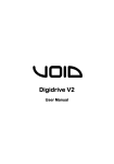
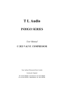
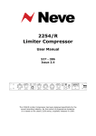
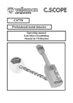
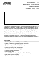
Dominator ™ II
Precision MultiBand
Peak Limiter
Models 720, 722
Model 720
The Dominator II from Aphex Systems is a stereo multiband peak limiter designed to fit
a wide range of applications. Through the use of multiband techniques along with new
proprietary circuits, the audibility of limiting action has been greatly reduced, especially
when compared to conventional limiters. This means that greater limiting depth is
possible, resulting in higher loudness with maintained audio quality. At virtually any
limiting depth, the Dominator II is free of “hole punching”, “dullness”, and most other
effects normally associated with limiters. As a peak overshoot protection limiter, the
Dominator II is undetectable in line while it absolutely prevents peak levels from
exceeding a user settable output level. In addition, the desired limiting effects of
greater audio density and increased “punch” are readily available with the Dominator II.
FEATURES
•
•
•
•
•
•
•
•
•
•
•
Peak Ceiling Trimmable in 0.2dB Steps Over a 34dB Range
3 Bands of Limiting with Switchable Crossover Frequencies
Patented Automatic Limit Threshold (ALT) Circuitry
Freedom from Pumping
Freedom from Spectral Gain Intermodulation
Adjustable Density (Relative Crest Height)
Calibrated Detented Potentiometers
104dB Dynamic Range
LF and HF EQ Provides Shaping Equalization Below Peak Ceiling
Relay Bypass, Remote Controllable
Servo-Balanced Transformerless Inputs and Outputs
Aphex Dominator II
Precision MultiBand Peak Limiter
Models 720, 722
Why is the Dominator So
Special?
A very significant problem with wideband processing
is “spectral gain intermodulation” which occurs when
one part of the spectrum controls the level of another
part. A typical situation is a vocalist being “sucked
down” every time the kick drum hits.
Since most energy is contained in the lower
frequencies, they tend to control the level of the entire
spectrum. When the lower frequencies are above the
limit threshold the higher frequencies are attenuated
thus causing the output to sound dull.
Multiband processing solves these problems by
splitting the audio into two or more frequency bands
and processing each band separately. However, more
bands often result in many more parameters to control
including a method of summing the bands together
again. While giving the user flexibility, it also requires
different settings for almost every different source.
The Dominator ll uses program dependent, intelligent
circuits to reduce the number of controls. The user,
therefore, has flexibility to shape the sound while
quickly and easily achieving the goal of consistent,
effective limiting.
The Secret Ingredient: ALT
A multiband processor splits the audio into separate
bands, limits each band individually and then sums the
bands together again. Even though each band’s peak
output is predictable, summing the bands together
produces an unpredictable peak output.
One conventional approach to making the summed
output predictable is to use a wideband limiter after the
summing. This, however, introduces all the drawbacks
of wideband limiting discussed above.
Another approach is to use a clipper on the summed
output. This causes too much clipping distortion if the
summed output is too high. In order to avoid this
distortion the limiters’ thresholds are set very far below
the clipper threshold. The drawback is a loss of
loudness and, due to the lower thresholds, much
greater amount of processing.
The Dominator ll uses a patented method to produce
a predictable peak output while maintaining maximum
loudness without audible distortion- the Automatic Limit
Threshold (ALT). The outputs of the three bands are
summed and sent to the ALT detector circuit. If the sum
exceeds a reference value, the ALT reduces the
thresholds of the individual limiters. When the summed
output falls below the reference value the limit
thresholds return to their original setting.
The ALT circuit has a self-adjusting finite attack time.
The amount of time it takes to lower the thresholds of
the limiters is the length of time the limiters’ overshoot
may be in the clipper. The reference value of the ALT in
relation to the clipper determines the depth of clipping.
Both parameters are set by the Density control. When
the Density control is set higher, the ALT reference gets
closer to clipping, and the attack time is slower,
producing more clipping. The opposite occurs when
Density is set lower. The “0 RCH” position for the
Density control emulates the standard parameters of
the original Studio Dominator Model 700, and is
recommended for general use.
PROCESS OFF/ON switches the audio
through the unit or
through bypass relays.
LF EQ - adjust input
level to the low
frequency band ±5dB.
Center detent is flat
response below limiting.
RELEASE - adjusts
release time of the
limiters between
150mSec (fully
clockwise) and 7Sec
(fully counter-clockwise).
STEREO
forces th
band to
limiting
the othe
band in
has a gr
limiting.
INPUT GAIN - adjusts
input level ±15dB.
Center detent is unity
gain.
XOVER 1 - switches
the crossover point
between low and mid
bands from 100Hz to
HF EQ - adjusts input
level to the high
frequency band ±5dB.
Center detent is flat
XOVER
crossov
mid and
1.7kHz
Model 720
It should be noted that there is only one ALT circuit
controlling both channels equally. This provides global
stereo balance and imaging by assuring that both
channels always limit at the same threshold. This
does cause an interaction if the Dominator ll is used
as two independent channels. Therefore, we do not
recommend such a practice.
Model 722 Broadcast
Dominator
Pre-emphasis is an equalization curve expressed
as a time value based on the ratio of a resistor and
capacitor. The higher the value, the greater the
equalization. It has been employed as a noise
reduction technique for broadcast and transmission
links. There are primarily two world standards- 50 and
75 microseconds.
Model 722
The Dominator ll Model 722, has separately
switchable pre and de-emphasis curves. When
pre-emphasis is switched in, either 50 or 75
microseconds, the equalization curve is added
after the input stage and before the limiters. When
de-emphasis is switched in, the complementary
de-emphasis curve is inserted after the final clipper
and before the output stage.
When both pre and de-emphasis are switched in
and when input is below threshold, the frequency
response of the output is flat. As the input increases
above threshold, the output takes the shape of the
de-emphasis curve.
When both pre and de-emphasis are switched out,
the Model 722 works exactly like the Model 720.
ach
and of
nnel
of
he
en
om
Applications
Sound Contracting — protection of amplifiers and
speakers from overload; increased loudness;
maximized use of available power.
Recording — preventing sudden peak overload of
mixer or recorder; tightening tracks; special effects,
etc.
Mixing — used as a program limiter, the Dominator ll
will keep a track “rock steady” for “layering” into or on
top of a mix.
Digital Sampling — obtaining good full scale samples
free from peak overload, i.e. no more missed samples.
Digital Recording — insuring clean recording by
stopping clipping of peaks and overshoots. Maximizes
bit usage for less distortion.
Satellite Uplink — Modulation control to prevent
splattering on high frequency audio, gives reduced
distortion, better signal-to-noise.
Broadcasting — AM and FM modulation control for
increased loudness; cleaner sound; use in production
for greater consistency of tapes, punchier voice-overs.
Location Film Shoots — anti-crash for dialog and
sound effects recording.
Post Production — Soundtrack peak control;
managing difficult dialog; controlling transient sound
effects.
Optical Recording and Transfer — prevents “valve
clash”, gives higher average level with low distortion
and better signal-to-noise performance.
Analog Disk Mastering — peak control for high
allowable average cutting levels; less limiter
degradation to the program; brighter, punchier sound.
C/D Mastering — peak and density control for more
accurate digitizing, cleaner sound requiring less error
correction on playback; no limiter induced sound
degradation.
STL & Phone Line Driver — maximize signal-tonoise without overload distortion.
Video and Audio Tape Duplication — “Hotter”
transfers without saturation.
RCH DENSITY - adjusts
the Relative Crest Height
(RCH) of the output.
The higher the RCH
(clockwise) the louder the
output. The lower the
RCH (counter-clockwise)
the lower the average
level in the output.
RANGE - when switched
to the “.10” position it adds
a 10dB boost in the input
and a 10dB cut in the
output. The PEAK CEILING
is therefore 10dB lower
than the settings shown
on COARSE and FINE
controls.
LIMITING (meter) displays the limiting
(from gain reduction
and clipping) in the
channel with the
greatest amount of
limiting.
FINE - adjusts the
PEAK CEILING by
±1dB in 0.2dB steps.
COARSE - switches
the PEAK CEILING
in 2dB steps from +2
to +24dB(pk).
POWER - switches
AC mains on and off.
“Off” position engages
bypass relays.
Dominator ™ II
NOMINAL OPERATING LEVEL
(Peak Ceiling RANGE switch)
INPUT
Connector:
Type:
Models 720, 722
0dBu (for use with +4 or +8dBu)
-10dBu
Nominal Level:
Maximum Level:
CMRR (typical):
RF Rejection:
3-Pin XLR female (pin 1 ground, pin 2 positive, pin 3 negative)
Transformerless, servo balanced with passive 4th order RF filter
Chassis grounded per AES standards
19.5 kΩ Unterminated;
same
600Ω with rear-panel terminator engaged
same
(terminator lifts in bypass)
from 0dBu to +8dBu
from -10dBu to 0dBu
+26dBu
+16dBu (+14.8dBV)
> 50dB 20Hz to 10kHz
same
> 28dB at 800 kHz; > 60dB above 2 mHz
same
OUTPUT
Connector:
Type:
Output Impedance:
Nominal Level:
Maximum Level:
3-Pin XLR male (pin 1 ground, pin 2 positive, pin 3 negative)
Transformerless, servo balanced, chassis grounded per AES standards
65Ω
same
from 0dBu to +8dBu
from -10dBu to 0dBu
+25dBu PK*
+15dBu PK*
Impedance:
AUDIO (Controls set for unity gain, no limiting and flat response except as otherwise noted)
Frequency Response:
+0.2dB 4.5Hz - 50kHz
same
Dynamic Range:
> 108dB
> 106dB
Hum & Noise (unweighted, 22 Hz - 22 kHz):
< -82dBu
< -90dBu
Crosstalk:
< -60dB up to 10kHz
same
THD (Ref.: 1kHz, no limiting):
< 0.006% (+12dBu in)
< 0.006% (+2dBu in)
SMPTE IMD:
< 0.006% (+12dBu in)
< 0.006% (+2dBu in)
720/722 CONTROL & METERING PARAMETERS (on front panel unless otherwise noted)
INPUT GAIN:
+14/-21 dB typical
same
PROCESS ON/OFF:
ON: Active / OFF: Hardwire Bypass
same
LF EQ Boost/Cut:
± 5 dB
same
HF EQ Boost/Cut:
± 5 dB
same
XOVER 1 Frequency:
100 Hz / 210 Hz
same
XOVER 2 Frequency:
1.7 kHz / 3.4 kHz
same
RELEASE Time:
150 mSec to 7 Sec
same
RCH (Relative Crest Height) DENSITY:
-5 to +5
same
STEREO COUPLING:
ON / OFF
same
PEAK CEILING:
+1 to +25dBu (PK)**
-9 to +15dBu (PK)**
Peak Ceiling is adjusted with the COARSE (2dB steps), FINE (0.2dB steps)
and RANGE (0dB/-10dB) controls
LIMITING Meter:
10 segment meter indicates up to 15dB of gain reduction in the channel
with the greatest amount of limiting
600 OHM INPUT TERMINATION:
Each channel is switchable on rear panel (lifts in bypass)
REMOTE Control Jack:
A four pin RJ11 telephone-style connector on the rear panel provides remote
control capacity of the PROCESS ON/OFF bypass relays and dry “tally”
contact for a remote status indicator
722 CONTROL PARAMETERS (722 only)
EMPHASIZED LIMITING (switches are located on the rear panel with LED function indicators located on the front panel)
DE-EMP (De-emphasis):
ON / OFF
same
PRE-EMP (Pre-emphasis):
ON / OFF
same
TIME CONSTANT (Microseconds):
75mS / 50mS
same
OTHER SPECIFICATIONS
Power Input:
IEC standard receptacle with voltage selector, fuse and filter
Power Requirements:
100, 120, 220, or 240 VAC; 50 or 60 Hz
Power Consumption:
30 watts maximum
Power Fuse:
Slow blowing type- 100/120 VAC: 0.375 A; 220/240 VAC: 0.25A
Net Weight:
6 lbs. (2.72 kg)
Shipping Weight:
9 lbs. (4.08 kg)
Dimensions:
19” W x 1.75” H x 9.63” D (482.6 mm x 44.5 mm x 244.6 mm)
EIA Mounting:
Mounts in standard 19” rack, using 1 RU of vertical space and 8.8”
(223mm) of depth behind front panel (not including power or I/O cables)
* Maximum Output Level is limited by the PEAK CEILING setting. The output stage is capable of +26dBu into 600Ω.
** dB (PK) = peak value of sine wave.
11068 Randall Street • Sun Valley, CA 91352 • (818) 767-2929 • FAX (818) 767-2641
Aphex is proudly American…100% owned, engineered and manufactured in the U.S.A.
Aphex is a registered trademark of Aphex Systems, Ltd.
Aphex is constantly striving to maintain the highest professional standards. As a result of these efforts, modifications may be made from time
to time to existing products without prior notice. Specifications and appearance may differ from those listed or shown.