1
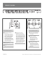
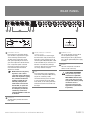
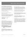
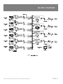
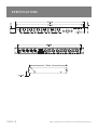
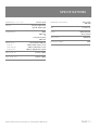
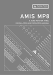
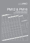
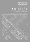
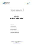
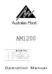
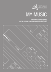
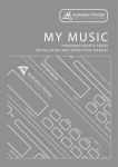
AMIS ZRM4
6 X 4 ROUTING MIXER
INSTALLATION AND OPERATION MANUAL
INTRODUCTION AND CONTENTS
The AMIS ZRM4 is an easy to use, yet highly featured 1 RU zone
routing mixer. It features 6 inputs that can be balanced XLR mic or
dual RCA/balanced XLR line level, all of which are available to any
combination of 4 zone outputs.
Input #1 can be designated as a paging input with priority over all
other inputs, individually selectable at each zone output. Front panel
switches with LED indication provide for the simple routing of each
input. Each input has bi colour status LED indication & 2 stage
equalization. Each input has an internal gain trim which can provide
a further +/- 15dB of gain, to allow the perfect set up of input gain no
matter what the input signal may be. Phantom power & high pass
filters are also supplied per input.
Each balanced XLR zone output features a dual colour status LED
& switchable paging mic priority. Remote VCA's are available for each
output allowing for a wall mounted volume control to be installed in
remote zones allowing for a volume range from off to whatever the
master level on the AMIS ZRM4 relevant zone output is set to.
INTRODUCTION
3
FRONT PANEL
4
REAR PANEL
5
INTERNAL ADJUSTMENTS
6
BASIC SETUP AND OPERATION
7
ADVANCED FEATURES
8
BLOCK DIAGRAM
9
SPECIFICATIONS
10
Alert, Evacuation, Bell & Pre Announce tones are provided on board.
The AMIS ZRM4 is a compact yet extremely versatile zone routing
mixer which makes the complex task of multizone signal routing
simple & cost effective.
AUS, EUR, USA
Copyright 4th Mar 2005
Rev A: 4th Mar 2005
This symbol is intended to alert the user to the presence
of uninsulated “dangerous voltage” within the product’s
enclosure that may be of sufficient magnitude to
constitute a risk of electric shock to persons.
This symbol is intended to alert the user to the presence
of important operation and maintenance (servicing)
instructions in the literature accompanying the appliance.
Caution:
AMIS ZRM4 INSTALLATION & OPERATION MANUAL
To prevent electric shock do not use this (polarised) plug
with an extension cord, receptacle or other outlet unless
the blades can be fully inserted to prevent blade exposure.
To prevent electric shock, match wide blade of plug to
wide slot, fully insert.
PAGE 3
FRONT PANEL
1
3
4
2
6
SWITCHES
These four switches allow you to
assign this channel's input signal to
any of the four outputs. When the
input is assigned, the yellow LED
next to the switch will light up.
Any combination of buttons may be
pushed in (selected) at any time, to
select multiple (and therefore mixed),
input signals to any output.
2 TONE CONTROLS
Each input has a two stage shelf EQ.
3 LEVEL
Controls the level of the input signal.
PAGE 4
7
OUTPUT CONTROL SECTION
INPUT CONTROL SECTION
1 OUTPUT ASSIGNMENT
5
4 INPUT STATUS LEDS
Each input has a status LED
indicator. The LED is green when
there is signal present and red if the
signal is approaching clip. The LED
begins to light red when the internal
signal level is 6dB before clip and is
solid red when it is 3dB before clip.
Note that the front panel level
control is post status LED and as
such, the status LED is NOT affected
by the level control. See internal
adjustment section on page 6.
5 OUTPUT LEVEL CONTROLS
These four pots control the level
of each output.
6 PRIORITY OVERRIDE
ENABLE SWITCHES
When active, these switches
allow input channel #1 to have
priority over all other inputs for
the selected output.
7 OUTPUT STATUS LEDS
Each output has a status LED
indicator. The LED is green when
signal is present on the output and
is red when the signal peak is above
0dBu (0.775v).
AMIS ZRM4 INSTALLATION & OPERATION MANUAL
REAR PANEL
6
5
2
3
1 CHANNEL INPUTS
Each channel has a dual RCA and XLR
input. The RCAs accept line level signals
and are internally summed to mono.
The XLR accepts balanced mic or line
level signals depending on the internal
gain switch adjustment. The XLR will also
have +15v phantom power if selected
on the internal switch. See page 6 for
more information about the internal
adjustments available.
☛
NOTE: Channel #1 is the priority
input and as such is able to
cause other signals to be ducked
when active. If you have a paging
mic, it should be connected to
channel #1. Channel #1 is not
affected by muting from the
chime module or level control
from the VCAs, so signals that
need to be muted in the event
of an emergency or need to be
controlled by a remote level
control should NOT be connected
to channel #1.
4
1
3 CHIME MODULE CONTROL
CONNECTIONS
These connections are used to trigger
the internal tones. Only one tone can be
triggered at a time. Triggering occurs by
connecting the ALERT, EVAC, BELL or PRE
terminal to COM. The pre-announce and
bell tones are routed along with input
channel #1, whilst the evac and alert tone
are always routed to all outputs.
4 VCA
Each output level may be controlled by
a RC1 remote wall panel or 500k ohm log
(A) pot. This connector provides
connection for these panels. The VCA is
in series and before the master output
level controls, so that setting either VCA
of Master level control to zero will mute
the output.
5 POWER 20V AC
This 2.1mm connector accepts 20v AC
from the provided power supply.
Alternatively, the unit may be powered
from a 24-34v regulated DC power supply
or battery.
6 EARTH
The earth stud provides a location to
connect a mains earth strap.
A NOTE ABOUT GROUNDING:
It may be necessary in some
circumstances to ground the
AMIS ZRM4 to eliminate noise
in the system. This can be done
using the earth stud or by making
sure that the chassis is
electrically connected to the
equipment rack (which should
be grounded).
2 OUTPUTS
The output XLRs provide balanced line
level signals.
AMIS ZRM4 INSTALLATION & OPERATION MANUAL
PAGE 5
INTERNAL ADJUSTMENTS
1
2
3
4
1 HPF
When this switch is in the "HPF OUT"
position, the signal bypasses the high
pass filter. Otherwise the signal is filtered
by a high pass filter with a knee of
approximately 150Hz. This is useful in
removing "thumps", "pops" and "rumble"
when using the input with a lectern or
handheld microphone.
5
4 GAIN TRIM
The input gain can be cut or boosted by
up to 15dB using this control. This control
affects both the XLR and the RCA inputs.
This allows a wide rage of program
sources to be set up with optimum gain
structure. With the gain trim in the centre
position, the boost/cut is set to 0dB.
See the block diagram on page 9 for
details of the gain structure.
2 PHANTOM
15v phantom power is available for
condenser or electret microphones on the
XLR input when this switch is in the
"PHANTOM ON" position.
5 TONES LEVEL
This controls the level of all the tones
generated by the tone module.
3 MIC / LINE
These two switches control the sensitivity
of the XLR input. In the "MIC" position the
XLR input is suitable for use with
microphones; in the "LINE" position the
XLR input is suitable for use with a
balanced line level signal.
☛
NOTE: Both MIC/LINE
switches must be in the same
position for correct operation
of the balanced input. The
MIC/LINE switches only affect
the XLR input.
PAGE 6
AMIS ZRM4 INSTALLATION & OPERATION MANUAL
BASIC SETUP AND OPERATION
The inputs of the AMIS ZRM4 can accommodate a wide range
of sources including dynamic microphones, DVD and CD players.
The zone outputs may be used to drive power (booster) amplifiers,
mixers or mixer amplifiers. Each installation will require setting the
appropriate relative mix of levels between microphones, program
sources and tones for each zone and balancing between the zones.
Because of the variation in levels between the possible sources,
AMIS ZRM4 offers a number of gain stage adjustments so you can set
the correct levels for your application.
TEST THE INPUT LEVELS
For each source, try to achieve the highest signal level possible.
i.e. for a CD player, cassette deck or other music source, put on the
loudest anticipated program music or for a paging mic make a loud
page. During this signal condition, the input status LED should light
green and may occasionally turn red for a short period.
If the status LED stays red (more than 5% of the time), you should
reduce the input gain trim. If the status LED never turns red at all,
you may wish to increase the input gain trim if required.
Also consider what the outputs are driving….
ASSIGN THE SOURCES TO THE OUTPUTS
Setting up correct gain structure through the whole system is
important to achieve optimal results.
For each input, activate the appropriate output assignment switches to
the outputs you wish the signal to be routed. Yellow LED's will indicate
which input is routed to which output
The following step by step procedure has been devised to assist during
the setup process. When the AMIS ZRM4 was shipped to you from the
factory, it was set up in a particular way. In the following procedure it
is essential that you are starting from these initial settings.
SET UP THE PRIORITY FUNCTION
+ Program Input Gain Controls
+ XLR Mic/Line switch
+ Input Level Controls
+ Output Level Controls
SET THE LEVELS
– half (12 o’clock)
– MIC
– off
– off
CONNECT THE SOURCES
First connect all the required sources to the appropriate input
connectors. If the source is a microphone, set the MIC/LINE switches
to the "MIC" position. If the source is an electret or condenser
microphone, set the phantom switch to the "PHANTOM ON" position.
If the source is a microphone used for speech such as for paging,
set the high pass filter switch to the "HPF ON" position. If one of
the sources needs to have priority over the some other sources
(paging or jukebox), ensure that it is connected to input channel
#1 as this is the designated priority input.
☛
If a priority signal such as a paging mic or line source is required,
switch the priority override enable switch to the on position (in) for
that zone. (See page 8 for further information)
Turn the input levels up to 5. For each output, turn up the level until it is
at an appropriate level for the listening environment. You will now have
to adjust the relative levels of the inputs to achieve a good balance for
each zone. It is generally a good idea to set up the priority signal (if
any) first. The aim of these adjustments is to have all level controls
at between 3 and 7. This may not be possible however. A good rule of
thumb is that input level controls should be higher than the output
level controls.
NOTE: The high pass filter has a knee around 160Hz
and a roll-off of 6dB/octave. Using the HPF helps to
eliminate thumps and rumble often heard through
paging mics.
CONNECT THE OUTPUTS
Turn the amplifiers off. Connect the AMIS ZRM4’s outputs to the
amplifiers' line level input. Check that the AMIS ZMR4 is on, then turn
on the amplifiers. If the amplifiers have a level controls, set them to
maximum.
AMIS ZRM4 INSTALLATION & OPERATION MANUAL
PAGE 7
ADVANCED FEATURES
TONE CONTROLS
TONE MODULE
Each input channel includes bass and treble trim pots which may be
used to adjust the tone of the signal. The bass trim offers +/- 12dB of
cut/boost to signals at 100Hz. The treble trim offers +/- 10dB of
cut/boost to signals at 10kHz.
The tone module generates four separately triggerable and
priorioritised tones. They are listed in order of highest to lowest
priority. Each tone is triggered by shorting the "COM" pin of the tone
module control lines connector to its associated pin.
Using the bass cut in association with the high pass filter is useful for
further reduction of rumble from microphones.
EVAC - An evacuation signal. Triggered by shorting the EVAC pin to
the COM pin. The EVAC signal will continue until the short is removed.
Triggering the EVAC signal will mute all inputs except channel #1.
☛
☛
NOTE: Attempting to add bass to systems that can not
reproduce bass well (such as transformer coupled
ceiling speakers or horn speakers) will only reduce
the headroom of the system and contribute to
distortion.
NOTE: adding bass or treble boost may cause the
input to clip, so keep an eye on the input’s status LED,
and reduce the gain trim if required.
ALERT - An ALERT/alarm signal. Triggered by shorting the "ALERT"
pin to the "COM" pin. The ALERT signal will continue until the short
is removed. Triggering the alarm signal will mute all inputs except
channel #1.
BELL - A chime like a BELL being struck twice, a short gap and then
repeated. Triggered by shorting the "BELL" pin to the "COM" pin.
The BELL signal will continue until the short is removed.
PRIORITY OVERRIDE
Each output channel has the ability to mute all other input signals in
the selected output when there is signal present on channel #1,
if channel #1 is assigned to that output. To enable this function activate
(press in) the "CH1 Priority Enable" switch for the required output and
assign channel #1 to that output. This is useful for paging microphones,
juke boxes and other situations where an occasional signal needs to
interrupt the normal programme.
PRE-ANNOUNCE - A four note chime, suitable for use before a
page is made. Triggered by shorting the "PRE" pin to the "COM" pin.
The PRE-ANNOUNCE chime will sound only once for each time
the chime is triggered.
☛
NOTE: The bell and pre-announce chimes are routed
with signals from channel #1, thus any output which
has channel #1 assigned to it will also receive these
tones. The EVAC and ALERT signals are routed to all
outputs AFTER the level controls. This is to ensure
that all zones receive these tones.
☛
NOTE: Because EVAC and ALERT do not mute channel
#1, it is not advisable to connect a continuous source
(such as a radio or CD player) to this input.
REMOTE VOLUME CONTROL
The level of each output may be controlled via a RC1 remote level
control panel or 500k ohm log (A) pot. For each output there are two
pins on the connector labeled VCA on the rear panel. The RC1or 500k
ohm log (A) pot should be connected to these pins. Please note that the
remote level control inserts before and in-line with the output level
control so the RC1 sets the maximum output level (for normal signals)
and the front panel master attenuates from that level. Also note that
an RC1 control will have no effect on the signals from input channel #1
or any of the tones generated by the tone module This is so that
the paging can not be turned off in a zone it has been assigned to.
If paging is too loud in a zone, the master output level control for
that zone should be turned down.
☛
NOTE: If using a 500k ohm pot, the connections should
be made to the wiper terminal and the anti-clockwise
terminal. i.e. max resistance = max volume
PAGE 8
AMIS ZRM4 INSTALLATION & OPERATION MANUAL
BLOCK DIAGRAM
AMIS ZRM4 INSTALLATION & OPERATION MANUAL
PAGE 9
SPECIFICATIONS
PAGE 10
AMIS ZRM4 INSTALLATION & OPERATION MANUAL
SPECIFICATIONS
DIMENSIONS (h x w x d)
WEIGHT
POWER INPUT
44 x 482 x 188mm
Net 2.9kg Shipping 4.4kg
Net 6.4lb Shipping 9.7lb
20VAC
600mA max
or
24 to 34v DC regulated
600mA max
FREQUENCY RESPONSE
<5Hz to >22kHz
(0dB/-3dB)
THD
less than 0.1%
NOISE
CROSSTALK:
PHANTOM POWER
SENSITIVITY
RCA IN
XLR LINE IN
XLR MIC IN
(input required for 0dBu out)
-26dBu to +4dBu (39mV to 1.23 V)
-26dBu to +4dBu (39mV to 1.23V)
-60dBu to -30dBu (0.78mV to 25mV)
MAX LEVEL IN
>14.1Vrms (+25dBu)
MAX LEVEL OUT
>15.4Vrms (+26dBu)
AMIS ZRM4 INSTALLATION & OPERATION MANUAL
<-90dBu 20Hz-20kHz
(all pots centred)
<-65dB @1kHz
15VDC
PAGE 11
AUSTRALIA AND NEW ZEALAND
www.australianmonitor.com.au
SYDNEY
MELBOURNE
BRISBANE
ADELAIDE
PERTH
AUCKLAND
(NSW & ACT SALES)
(VIC & TAS SALES)
(QLD SALES)
(SA & NT SALES)
(WA SALES)
(NZ SALES)
149 Beaconsfield
Street Silverwater
NSW 2128
Private Bag 149
Silverwater NSW 1811
Phone: (02) 9647 1411
Fax: (02) 9648 3698
Email:
[email protected]
22/277
Middleborough Road
Box Hill VIC 3128
PO Box 151 Blackburn
South VIC 3130
Phone: (03) 9890 7477
Fax: (03) 9890 7977
Email:
[email protected]
42 Commercial Road
Fortitude Valley
QLD 4006
PO Box 871 Fortitude
Valley QLD 4006
Phone: (07) 3852 1312
Fax: (07) 3252 1237
Email:
[email protected]
31 Walsh Street
Thebarton
SA 5031
PO Box 157
Hindmarsh SA 5007
Phone: (08) 8352 4444
Fax: (08) 8352 4488
Email:
[email protected]
299 Fitzgerald Street
West Perth WA 6005
PO Box 404
North Perth
WA 6906
Phone: (08) 9228 4222
Fax: (08) 9228 4233
Email:
[email protected]
Unit B, 11 Piermark
Drive Albany 1331
New Zealand
PO Box 512
Albany 1331
Phone: (09) 415 9426
Fax: (09) 415 9864
Email:
[email protected]
EUROPE/ASIA/MIDDLE EAST
USA/SOUTH AMERICA
www.australianmonitor.com.au
www.australianmonitor.com
INTERNATIONAL SALES
SENNHEISER ELECTRONIC CORPORATION
149 Beaconsfield Street Silverwater NSW 2128 Australia
Private Bag 149 Silverwater NSW 1811
Phone: 61 2 9647 1411
Fax: 61 2 9648 3698
Email: [email protected]
1 Enterprise Drive
Old Lyme CT 06371 USA
Phone: 1 860 434 9190
Fax: 1 860 434 1759
Email: [email protected]