1
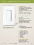
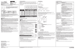
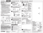
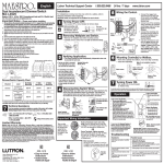
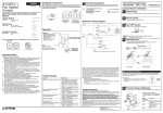
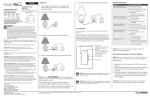
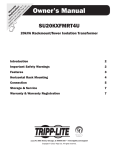
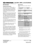
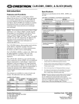
Installation Instructions
Please Read Before Installing
Designer-Style Maestro® Remotes
HD-RD, -RS
120/127 V ~, 50/60 Hz
Overview
The HD-RD Remote Dimmer and the HD-RS Remote
Switch are for use with HomeWorks Maestro Dimmers and
Switches.
Up to nine HD-RD Remote Dimmers may be used with a
HomeWorks Wired or RF Maestro Dimmer, and up to nine
HD-RS Remote Switches may be used with a HomeWorks
Wired or RF Maestro Switch.
Important Notes
HD-RD
HD-RS
Codes: Install in accordance with all local and national electrical codes.
Danger: These controls must not be used to control equipment which is not visible from every control location. They must also not be used to control equipment which could create hazardous situations such as entrapment if operated accidentally.
Examples of such equipment which must not be operated
by these controls include (but are not limited to) motorized
gates, garage doors, industrial doors, microwave ovens,
heating pads, etc. It is the installer’s responsibility to ensure
that the equipment being controlled is visible from every
control location and that only suitable equipment is connected to these controls.
Overheat Damage: To reduce the risk of overheating and
possibly damaging other equipment, do not install
to control receptacles or motor-operated appliances.
Environment: Ambient operating temperature:
0-40°C, 32-104°F, 0-90% humidity, non-condensing. Indoor
use only.
Spacing: If mounting one control above another, leave at
least 4 1/2" (114mm) vertical space between them.
Wallplates: Lutron Claro® and Satin ColorsTM wallplates are
recommended for best color match and aesthetic appearance. Do not paint controls or wallplates.
Cleaning: To clean, wipe with a clean damp cloth. DO NOT
use any chemical cleaning solutions.
Wallboxes: Lutron recommends using 3-1/2" (89mm) deep
wallboxes for easier installation. Several controls may be
installed in one multigang wallbox - see Multigang
Installations (page 2).
Remotes: Use only Lutron® HomeWorks Maestro Remote
Dimmers (HD-RD) with HRD/HWD-6D, -6ND, -10D, -10ND,
and -5NE controls. Use only Lutron HomeWorks Maestro
Remote Switches (HD-RS) with HRD/HWD-8ANS controls.
Up to 9 HD-RD or HD-RS controls may be used with a
HomeWorks Maestro Dimmer or Switch. Mechanical 3- or 4way switches will not work.
1
Multigang Installations
5. Attach Lutron Claro® or Satin ColorsTM wallplate adapter
In multigang installations, several controls are grouped horizontally in one multigang wallbox.
and wallplate.
a. Loosely install control mounting screws.
• No derating is required for Remotes.
b. Tighten wallplate adapter mounting screws snug.
• When ganging Remotes with dimmers or switches in the
same wallbox, derating is required for the dimmers or
switches. See the installation instructions that came with
the dimmer or switch for derating requirements.
c. Tighten control mounting screws until wallplate
adapter is flush to wall (do not over-tighten).
d. Snap wallplate onto wallplate adapter, and verify
that control is not submerged.
Note: Controls do not have fins that need to be removed for
multigang installations.
e. If control is submerged, loosen mounting screws
appropriately.
6. Complete wiring for all dimmers, switches and remotes in
Installation
this circuit.
Danger - Locate and remove fuse or lock circuit
breaker in the OFF position before proceeding.
Wiring with power ON may result in personal
injury.
7. Restore power. Check for correct local operation (see
Local Operation, page 5).
Short Circuit Check: Check the installation for short circuits before installing control(s). With power OFF, install
standard mechanical switch(es) between Hot and load.
Restore power. If lights do not work or a breaker trips,
check wiring. Correct wiring and check again. Install control(s) only when short is no longer present. Warranty is void
if control is turned ON with a shorted circuit.
1.
2.
Turn power OFF at fusebox or circuit breaker.
Prepare wires. When making wire connections, follow the
recommended strip lengths and combinations for the
supplied wire connectors. Note: Wire connectors provided are suitable for copper wire only.
Mounting Diagram
Control
Mounting
Screws
Large:
Strip insulation 1/2" (13mm) for #10 AWG
(6mm2), #12 AWG (4mm2) or #14 AWG
(2.5mm2).
Wallplate
Adapter
Mounting
Screws
Strip insulation 5/8" (16mm) for #16 AWG
(1.5mm2) or #18 AWG (1.0mm2).
Use to join one or two #12 or 14 AWG supply wires with one #10, 12, 14, 16 or 18
AWG control wire.
Large
3. Wire controls using Wiring Diagrams 1 and 2 (page 3).
When using power boosters or interfaces, use Wiring
Diagrams 3, 4, and 5 (page 4). Up to nine HD-RD or HDRS remotes may be connected to the -6D, -6ND, -10D, 10ND, -5NE, or -8ANS controls.
4. Push all wires back into the wallbox and loosely fasten
the control to the wallbox using the control mounting
screws provided. Do not pinch the wires.
2
Wallbox
Control
Included:
Wire Connectors (4)
Wallplate/Adapter purchased
separately.
Mounting Screws (2)
Wiring Diagram 1
Multi-Location Installation1
-6D, -10D with HD-RD
Hot
Black
Red
Remote Dimmer
Dimmer
Remote Dimmer
Black
Red
Black
Red
Lighting
Load
120/127VAC
50/60Hz
Green
Blue
Green
Blue
Green
Blue
Neutral
Wiring Diagram 2
Multi-Location Installation with Neutral1, 2
-6ND, -10ND, -5NE with HD-RD, -8ANS with HD-RS
Hot
Black
Red
Dimmer/
Switch
Remote
Dimmer/Switch
Remote
Dimmer/Switch
Black
Red
Black
Red
Lighting
Load
120/127VAC
50/60Hz
Green
Blue
Green
Blue
Green
Blue
White
Neutral
1 Up to 9 HomeWorks® Maestro® Remote Dimmers/Switches may be connected to the HomeWorks Maestro Dimmer/Switch. Total Blue
wire length may be up to 250' (76m).
2 Remote Dimmers/Switches must be connected on the Line side of a multi-location installation when used with Neutral wire Dimmers or
Switches.
3
Wiring Diagram 3
120/127VAC
50/60 Hz
Green
Blue
Green
Blue
Lighting
Load
NEUTRAL
Red
Black
Red
Black
Hot/Live
Dimmer
CONTROL
-6ND, -10ND with HD-RD
NGRX-PB
or
ELVI-1000
HOT IN
Remote
Dimmer
DIM HOT OUT
Installation with Power
Booster or ELV Interface1, 2
White
Neutral
Wiring Diagram 4
120/127VAC
50/60 Hz
Green
Green
Blue
FDBI-16A-120
NEUTRAL
CONTROL
Lutron® Hi-lume® Fluorescent
Dimming Ballast(s)
SW HOT
Red
Black
Red
Black
Hot/Live
Dimmer
HOT IN
Remote
Dimmer
-6ND, -10ND with HD-RD
DIM HOT OUT
Installation with Fluorescent
Dimming Ballast Interface1, 2
Orange
Blue
Black
White
White
Neutral
Wiring Diagram 5
Installation with Neutral and
Hi-Power Module1, 2
HP 2•4•6TM
Hi-Power Module
-6ND, -10ND with HD-RD
-8ANS with HD-RS
N3
H3 DH3 SH3
N2
H2 DH2 SH2
N1
H1 DH1 SH1
N N H H DH 1 2 3
Lighting
Load
Control
Terminals
Load
Terminals
N1
H1 DH1 SH1
N N H H DH 1 2 3
Remote
Dimmer/Switch
Black
Red
Green
Dimmer/Switch
Black
Red
Green
Blue
Blue
Hot/Live
120/127VAC
50/60 Hz
Neutral
Hot/Live
120-277VAC
50/60 Hz
Load Circuit
Neutral
White
Control Circuit
1 Up to 9 HomeWorks® Maestro® Remote Dimmers/Switches may be connected to the HomeWorks Maestro Dimmer/Switch. Total blue
wire length may be up to 250 ft. (76m).
2 Remote Dimmers/Switches must be connected on the Line side of a multi-location installation when used with Neutral wire Dimmers or
Switches.
4
Local Operation
Lamp Replacement
Pressing the Tapswitch on any Dimmer, Switch, or
Remote will alternately turn the lights ON and OFF. For
HD-RD, the ON level will be the level previously set
using the Dimming Rocker. Press and hold the top or
bottom of the Dimming Rocker to raise or lower the light
level.
For routine lamp replacement, remove power from the
fixture(s) by sliding the Front-Accessible Service Switch
(FASS) to the OFF position (left). After replacing lamps,
slide the FASS back to the ON position (right) to restore
power.
Double-tapping the Tapswitch on the HD-RD will turn the
lights ON to full. Pressing and holding the Tapswitch for
1/2 second (while ON) activates a 10-second long fadeto-off.
Danger - For any procedure other than routine
lamp replacement, power must be disconnected
at the main electrical panel.
Remote Dimmer Operation
Tapswitch
Tap on/off
Dimming Rocker
Press to Brighten
Press to Dim
OFF
ON
FASSTM
Front
Accessible
Service
Switch
Remote Switch Operation
Tapswitch
Tap on/off
OFF
ON
FASS
Front
Accessible
Service
Switch
5
Troubleshooting Guide
Symptom
Cause and Action
No lights at all
Power not present
• Circuit breaker OFF or tripped. Perform Short Circuit Check (see page 2).
• FASSTM in the OFF position. Move FASS to the ON position by sliding it to the right. Check both the
dimmer/switch and all of the remote dimmers/switches.
Wiring
• Wires shorted. Make sure the blue wires are not grounded or shorted to any other wires.
• Wiring error. Check wiring to be sure it agrees with installation instructions and wiring diagrams.
Lamps burned out
• Replace lamps.
Dioded lamps
• If dioded lamps are being used, replace with non-dioded lamps.
Lights turn ON when tapswitch is pressed, then turn
OFF
Wiring
• Wiring error. Check wiring to be sure it agrees with installation instructions and wiring diagrams.
Tapswitch stuck
• Tapswitch stuck at another location. Check to see that tapswitches are not sticking for all control locations in the circuit.
Light turns ON and OFF continuously
Load is less than minimum load requirement
Lights don’t switch when tapswitch is pressed
Wiring
• Make sure the load connected to the dimmer or switch meets the appropriate minimum load requirement for that control. See Load Specifications in the Installation Instructions for the dimmer or switch.
• Wires shorted. Make sure the blue wires are not grounded or shorted to any other wires.
• Wiring error. Check wiring to be sure it agrees with installation instructions and wiring diagrams.
Lights don’t switch ON/OFF
when HD-RD or HD-RS tapswitch is pressed
Wiring
• Wires shorted. Make sure the blue wires are not grounded or shorted to any other wires.
• Wiring error. Check wiring to be sure it agrees with installation instructions and wiring diagrams.
Lights don’t switch ON/OFF
from Keypad
Improper programming
• Check programming in HomeWorks® Utility.
Wiring
• Wires shorted. Make sure the blue wires are not grounded or shorted to any other wires.
• Wiring error. Check wiring to be sure it agrees with installation instructions and wiring diagrams.
6
Notes:
7
LIMITED WARRANTY
Technical and Sales Assistance
If you need assistance, call the toll-free Lutron
Technical Support Center. Please provide exact
model number when calling.
(800) 523-9466 (U.S.A., Canada and the Caribbean)
Other countries call:
Tel: (610) 282-3800
Fax: (610) 282-3090
Visit our Web site at www.lutron.com
Lutron Electronics Co., Inc.
7200 Suter Road
Coopersburg, PA 18036-1299
Made and printed in the U.S.A. 02/03 P/N 043-134 Rev. A 93-2605-02
Lutron will, at its option, repair or replace any unit that is defective in materials or manufacture within two years after purchase. For warranty service, return unit to place of purchase or
mail to Lutron at 7200 Suter Rd., Coopersburg, PA 18036-1299, postage pre-paid. Telephone
the Lutron Technical Support Center toll free at 800-523-9466. After the two year period, a
pro-rated warranty applies to this product until eight years after the purchase. For more information regarding this warranty contact your Lutron representative.
THIS WARRANTY IS IN LIEU OF ALL OTHER EXPRESS WARRANTIES, AND THE
IMPLIED WARRANTY OF MERCHANTABILITY IS LIMITED TO TWO YEARS FROM PURCHASE. THIS WARRANTY DOES NOT COVER THE COST OF INSTALLATION,
REMOVAL OR REINSTALLATION, OR DAMAGE RESULTING FROM MISUSE, ABUSE,
OR IMPROPER OR INCORRECT REPAIR, OR DAMAGE FROM IMPROPER WIRING OR
INSTALLATION. THIS WARRANTY DOES NOT COVER INCIDENTAL OR CONSEQUENTIAL DAMAGES. LUTRON’S LIABILITY ON ANY CLAIM FOR DAMAGES ARISING OUT
OF OR IN CONNECTION WITH THE MANUFACTURE, SALE, INSTALLATION, DELIVERY,
OR USE OF THE UNIT SHALL NEVER EXCEED THE PURCHASE PRICE OF THE UNIT.
This warranty gives you specific legal rights, and you may also have other rights which vary
from state to state. Some states do not allow limitations on how long an implied warranty lasts,
so the above limitation may not apply to you. Some states do not allow the exclusion or limitation of incidental or consequential damages, so the above limitation or exclusion may not
apply to you.
This product may be covered by one or more of the following U.S. patents: 5,248,919;
5,399,940; 5,637,930; D353,798 and corresponding foreign patents. U.S. and foreign patents
pending. Lutron, Claro, Maestro, Hi-lume and HomeWorks are registered trademarks and
Satin Colors, HP 2•4•6, FASS and the HomeWorks Logo are trademarks of Lutron Electronics
Co., Inc.
© 2003 Lutron Electronics Co., Inc.