1
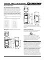
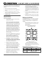
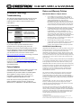
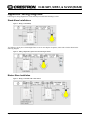
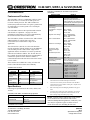
CLW-SW1, SWS1, & SLVS1(W/A/B)
CLW-SW1, CLW-SWS1, & CLW-SLVS1 Specifications
(Continued)
Introduction
SPECIFICATION
Features and Functions
The CLW-SW1 (-SW1) is a stand-alone wall box switch
that can also act as a Cresnet® device that reports to a
Crestron® control processor. The -SW1 includes two
isolated, non-polarized Cresnet wires (plus a ground wire)
for connecting to a Cresnet system over a twisted pair
wire with shield.
Available Colors/Textures
MATCHING LUTRON
FACEPLATE
W
W-S
CW-1-WH
Almond
A
CW-1-LA
Not Applicable
Smooth Almond
A-S
CW-1-LA
Black
B
Not Applicable
Smooth Black
B-S
CW-1-BL
Specifications
Following are specifications for the -SW1, -SWS1, and
-SLVS1.
CLW-SW1, CLW-SWS1, & CLW-SLVS1 Specifications
SPECIFICATION
DETAILS
Power Requirements
Line Power, 120 VAC, 60 Hz
Default Net ID
SW1: 82
SWS1: 83
(Continued on next column)
Crestron Electronics, Inc.
15 Volvo Drive Rockleigh, NJ 07647
Tel: 888.CRESTRON
Fax: 201.767.7576
www.crestron.com
3
Neon / Cold Cathode
These switches are available in a variety of colors and
textures. The table below shows the availability.
Smooth White
Version 3.117 or later
Magnetic Low Voltage
The CLW-SLVS1 (-SLVS1) is a slave unit that when
used in conjunction with the -SWS1 acts as an additional
switch control point in a multi-switch / single circuit
application. It does not connect to a Cresnet system and
cannot be used without a -SWS1. The -SLVS1 does not
have a mode selection switch and is not programmable. It
emulates the operation of the -SWS1 to which it is
connected unless the mode selection switch of the master
is set to “OFF”.
White
2-Series Control System
1,2
Update File
Incandescent / Tungsten
Halogen
The CLW-SWS1 (-SWS1) is similar to the -SW1 with the
added capability of working with a slave unit
(CLW-SLVS1) in a multi-switch / single circuit
application.
MODEL NUMBER
SUFFIX
Incandescent, Tungsten Halogen,
Fluorescent / High Intensity
Discharge (HID), Electronic Low
Voltage, Magnetic Low Voltage, Neon
/ Cold Cathode, General Purpose Fan
Load Ratings
The CLW-SW1 features a three-position mode selection
switch. Refer to “Operation ” on page 5 for more
information. In the absence of Cresnet communications,
the switch can still be used to control a load.
COLOR/
TEXTURE
DETAILS
Load Type
4
4
-SW1: 1000W
-SWS1: 1000W
-SLVS1: N/A
-SW1: 1000VA/750W
-SWS1: 1000VA/750W
-SLVS1: N/A
-SW1: 1000VA/750W
-SWS1: 1000VA/750W
-SLVS1: N/A
Electronic Low Voltage
-SW1: 1000W
-SWS1: 1000W
-SLVS1: N/A
Fluorescent / High
Intensity Discharge
(HID)
-SW1: 8A
-SWS1: 8A
-SLVS1: N/A
General Purpose Fan
-SW1: 3.0A
-SWS1: 3.0A
-SLVS1: N/A
Minimum Load
40W / 0.5A
Operating Temperature
and Humidity
32°F to 104°F (0°C to 40°C )
10 to 90% Relative Humidity
(Non-Condensing)
Dimensions and Weight
-SW1 and -SWS1:
Height: 4.13 in (10.48 cm)
Width: 2.38 in (6.03 cm)
Depth: 1.91 in (4.85 cm)
Weight: 4.4 oz (0.61 kg)
-SLVS1:
Height: 4.13 in (10.48 cm)
Width: 1.75 in (4.45 cm)
Depth: 1.91 in (4.85 cm)
Weight: 3.6 oz (0.50 kg)
1.
The latest software versions can be obtained from the Crestron
website. Refer to the NOTE following these footnotes.
2.
Crestron 2-Series control systems include the AV2 and PRO2.
Consult the latest Crestron Product Catalog for a complete list of
2-Series control systems.
3.
Refer to Derating Charts for Multigang Installations on pages 3
and 4.
4.
VA ratings are for input power to the transformer. If you do not
know the input power requirement of the transformer, use the
bulb’s wattage rating to determine proper rating.
NOTE: Crestron software and any files on the website
are for Authorized Crestron dealers and Crestron
Authorized Independent Programmers (CAIP) only. New
users may be required to register to obtain access to
certain areas of the site (including the FTP site).
Installation Guide – DOC. 6251B
(2009753)
06.07
Specifications subject to
change without notice.
CLW-SW1, SWS1, & SLVS1(W/A/B)
Physical Description
The -SW1 and -SWS1 contain one large pushbutton, a
light emitting diode (LED) with software adjustable
brightness*, and a three-position slider-switch, shown
after this paragraph. Line voltage connections are made at
the rear of the switch. Three Class 2 low voltage wires,
located on the front of the switch, provide a Cresnet
connection to a control system. The wires can be routed to
the bottom of the unit for placement outside of the wall
box. The -SLVS1 is similar to the -SW1 and -SWS1 but
does not have the slider-switch or the Class 2 low voltage
wires.
*
LED brightness can only be adjusted through Crestron programming
software.
CLW-SW1/SWS1 (L) and CLW-SLVS1 (R) shown in white
Physical view of CLW-SLVS1 (clockwise from top; Top, Side,
and Front)
1.91 in
(4.85 cm)
1.75 in
(4.45 cm)
3.81 in
(9.68 cm)
3.28 in
(8.32 cm)
2.70 in
(6.86 cm)
4.13 in
(10.48 cm)
1.50 in
(3.81 cm)
The -SW1, -SWS1, and -SLVS1 mount in a standard
wallbox and are covered using a decorative faceplate (not
included).
Physical view of CLW-SW1/SWS1 (clockwise from top; Top,
Side, and Front)
1.75 in
(4.45 cm)
Industry Compliance
This product is Listed to applicable UL Standards and
requirements by Underwriters Laboratories Inc.
E239013
2.38 in
(6.03 cm)
This device complies with part 15 of the FCC rules.
Operation is subject to the following two conditions:
(1) this device may not cause harmful interference, and
(2) this device must accept any interference received,
including interference that may cause undesired
operation.
1.91 in
(4.85 cm)
3.81 in
(9.68 cm)
3.28 in
(8.32 cm)
2.70 in
(6.86 cm)
4.13 in
(10.48 cm)
1.50 in
(3.81 cm)
2 • Stand Alone Wall Box Switch: CLW-SW1, SWS1, & SLVS1
CAUTION: Changes or modifications not expressly
approved by the manufacturer responsible for compliance
could void the user’s authority to operate the equipment.
NOTE: This equipment has been tested and found to
comply with the limits for a Class B digital device,
pursuant to part 15 of the FCC Rules. These limits are
designed to provide reasonable protection against harmful
interference in a residential installation. This equipment
generates, uses and can radiate radio frequency energy
and, if not installed and used in accordance with the
instructions, may cause harmful interference to radio
communications. However, there is no guarantee that
interference will not occur in a particular installation. If
this equipment does cause harmful interference to radio or
television reception, which can be determined by turning
Installation Guide – DOC. 6251B
CLW-SW1, SWS1, & SLVS1(W/A/B)
the equipment off and on, the user is encouraged to try to
correct the interference by one or more of the following
measures:
recommends using 3 ½” deep wallboxes. Several
devices can be installed in one wall box
(multigang). This requires the removal of side
sections (shown below) and the derating of the
switching device. For a smooth appearance, onepiece multigang faceplates (not supplied) can be
installed.
Reorient or relocate the receiving antenna.
Increase the separation between the equipment and
receiver.
Connect the equipment into an outlet on a circuit
different from that to which the receiver is connected.
Consult the dealer or an experienced radio/TV
technician for help.
Important Notes
Other Switch Devices: Mechanical 3- or 4-way
switches will not work with the -SW1, -SWS1,
or -SLVS1.
•
Spacing: If mounting one device above another,
leave at least 4 ½” vertical space between them.
Multigang Installations
Read before installation.
•
•
In multigang installations, several controls are grouped
horizontally in one wallbox. For a smooth appearance,
one-piece multigang faceplates (not supplied) can be
installed.
Codes: Install in accordance with all local and
national electrical codes.
Alternate wiring methods may be used for the
Class 2 wiring connection. The 2002 National
Electrical Code (Article 725-55) prohibits Class
2 conductors of the -SW1, -SWS1, and -SLVS1
to occupy the same outlet box as the power
conductors. The exception is Part D of Section
725.55 of the 2002 National Electrical Code,
which allows a device’s power conductors to be
installed near (0.25 inch minimum spacing)
associated Class 2 conductors in the same outlet
box. Consult the 2002 National Electrical Code
Handbook and your local electrical inspector
before proceeding.
1.
When combining controls in a wallbox, remove
inner side sections prior to wiring (refer to the
following figure).
Inner Sections of Multiganged Switches
REMOVE INNER SECTIONS
Do not use the supplied butt-splice connectors if
the Class 2 conductors are to be installed in the
wallbox with the power conductors. Use
approved connectors (supplied by others) to
make Class 2 connections inside the wallbox.
•
CAUTION: TO REDUCE THE RISK OF
OVERHEATING AND POSSIBLE DAMAGE
TO OTHER EQUIPMENT, DO NOT INSTALL
TO CONTROL A RECEPTACLE.
•
•
•
•
Wiring: Use copper wire only. For supply
connection, use wires rated for at least 75°C.
Load Type: The -SW1, -SWS1, and -SLVS1 are
designed for use with permanently installed
incandescent, fluorescent (non-dimmable), low
voltage, neon/cold cathode, HID, general
purpose fan, or tungsten halogen lighting.
Temperature: The -SW1, -SWS1, and -SLVS1
are designed to be used where temperatures are
between 32° to 104°F (0° to 40°C).
Wallboxes: Devices mount in standard
wallboxes. For easy installation, Crestron
Installation Guide – DOC. 6251B
DO NOT REMOVE OUTER SECTIONS
The load capacity must also be derated. The
following charts provide derating information for
various applications.
Derating Information for Incandescent, Tungsten Halogen,
and Electronic Low Voltage Applications
Part Number
No Side
Removed
One Side
Removed
Two Sides
Removed
-SW1
1000W
600W
400W
-SWS1
1000W
600W
400W
-SLVS1
No Derating Necessary
Stand Alone Wall Box Dimmer: CLW-SW1, SWS1, & SLVS1 • 3
CLW-SW1, SWS1, & SLVS1(W/A/B)
Derating Information for Magnetic Low Voltage and
Neon/Cold Cathode Applications*
Part
Number
No Side
Removed
One Side
Removed
Two Sides
Removed
-SW1
1000VA/750W
600VA/450W
400VA/300W
-SWS1
1000VA/750W
600VA/450W
400VA/300W
-SLVS1
*
No Derating Necessary
VA ratings are for input power to the transformer. If you do not
know the input power requirement of the transformer, use the bulb’s
wattage rating to determine proper rating.
NOTE: The GRAY (Cresnet) wires are not polarized.
These wires can be connected to either the Y or Z line on
a Cresnet port.
NOTE: The BLACK wire (Cresnet ground) should not
be grounded with the GREEN (Ground) wire on the
-SW1/-SWS1.
NOTE: Crestron recommends using Cresnet-DM cable
for connecting the -SW1 and -SWS1 to the Cresnet
network.
Derating Information for Fluorescent/HID Applications
Part
Number
No Side
Removed
One Side
Removed
Two Sides
Removed
-SW1
8A
5A
3A
-SWS1
8A
5A
3A
-SLVS1
No Derating Necessary
Derating Information for General Purpose Fans
Part
Number
No Side
Removed
One Side
Removed
Two Sides
Removed
-SW1
3A
3A
3A
-SWS1
3A
3A
3A
-SLVS1
2.
No Derating Necessary
To remove a side section, bend the side section
back and forth with a pair of pliers until the
section breaks off from the mounting plate. Use a
file or sandpaper to remove any excess metal.
Prewire for Master Application
Each device has two Class 2 low voltage wires (plus a
ground wire) that provide a Cresnet connection over
shielded twisted-pair to a Crestron control system. These
wires are routed to the bottom of the device for
connection outside of the wallbox. The low voltage wires
are pulled from each device location to the Crestron
control system or a Crestron connection block device. Use
#22 AWG, twisted, shielded, 2-conductor wire. Wiring
can be daisy chained, T-tapped, or home run back to the
control system. Refer to the following wiring diagram.
Wiring Diagram of CLW device to Cresnet
Installation
WARNING: Turn off power at the circuit breaker.
Installing with power on can result in serious personal
injury and damage to the device.
NOTE: The -SW1, -SWS1 require a neutral wire for
operation. If no neutral is present, contact a licensed
electrician for installation, otherwise the device will not
work.
NOTE: The -SWS1 must be installed in the same
wallbox that contains the connections to the load.
NOTE: New installations should be checked for short
circuits prior to installing the -SW1, -SWS1, or -SLVS1.
With power off, close the circuit and restore power. If the
load does not work or a breaker trips, check and correct
the wiring or fixture (if necessary). Install the -SW1,
-SWS1, or -SLVS1 only when the short is no longer
present. The warranty is void if the -SW1, -SWS1, or
-SLVS1 is installed and operated with a shorted load.
When installing a -SW1 or a -SWS1 without a slave,
follow the instructions in “Wiring a -SW(S)1 (No
Slaves)” below. If wiring a -SWS1 with a -SLVS1, refer
to “Wiring a -SWS1 with One or More
-SLVS1s” on the next page.
Wiring a -SW(S)1 (No Slaves)
The following describes the installation of a stand-alone
-SW1 or -SWS1.
1.
Turn power off at the circuit breaker.
2.
Pull Class 2 low voltage wires through a hole in
the drywall located outside of the electrical box,
to the Crestron control system or a Crestron
connection block device. Leave wires outside of
the wallbox for connection to the -SW1 or
-SWS1.
NOTE: Alternate wiring methods may be used
for the Class 2 wiring connection. Refer to
4 • Stand Alone Wall Box Switch: CLW-SW1, SWS1, & SLVS1
Installation Guide – DOC. 6251B
CLW-SW1, SWS1, & SLVS1(W/A/B)
section 725-55, Part D of the 2002 National
Electric Code.
3.
4.
5.
3.
Wire the switches as shown in Figure 3 on
page 8.
Wire the switch as shown in Figure 1 on
page 8.
NOTE: Do not connect the BLUE (Slave) wire
to the Black (Hot) or RED (Load) wires.
NOTE: The RED (Load) and BLACK (Hot)
wires are #14 AWG. The BLUE (Slave) and
WHITE (Neutral) wires are #18 AWG. The
GREEN (Ground) wire is #16 AWG. The GRAY
(Cresnet) wires are #22 AWG. The BLACK wire
(Cresnet ground) paired with the GRAY
(Cresnet) wires is #22 AWG.
NOTE: The RED (Load) and BLACK (Hot)
wires are #14 AWG. The BLUE (Slave) and
WHITE (Neutral) wires are #18 AWG. The
GREEN (Ground) wire is #16 AWG. The GRAY
(Cresnet) wires are #22 AWG. The BLACK wire
(Cresnet ground) paired with the GRAY
(Cresnet) wires is #22 AWG.
NOTE: Since the -SWS1 is installed without a
-SLVS1, the BLUE lead (Slave) should be
capped.
NOTE: If a -SWS1 is installed without a
-SLVS1, the BLUE lead (Slave) should be
capped.
Other Wiring
For another scenario that may be encountered
during installation, refer to Figure 2 on page 8.
NOTE: The WHITE (Neutral) connection on
the -SLVS1 is optional and is only required for
operation of the LED. If the neutral is not
available, the white lead should be capped off.
Splice the gray wires of the -SW1 or -SWS1 to
the Class 2 low voltage wires connected to the
Crestron control system or a Crestron connection
block device. Push the wires and the splices into
a hole in the drywall to provide the necessary
separation.
Push all power wires back into the wallbox and
fasten the device to the wallbox with the
provided screws.
6.
Attach decorative faceplate.
7.
Restore power at the circuit breaker.
Wiring a -SWS1 with One or More
-SLVS1s
NOTE: The -SWS1 must be installed in the same
wallbox that contains the connections to the load.
The following describes installation of a -SWS1 master
with a -SLVS1 slave.
4.
Splice the gray wires of the -SWS1 to the Class 2
low voltage wires connected to the Crestron
control system or a Crestron connection block
device. Push the wires and the splices into a hole
in the drywall to provide the necessary
separation.
5.
Push all power wires back into the wallbox and
fasten the devices to their respective wallboxes
with the provided screws.
6.
Attach decorative faceplates.
7.
Restore power at the circuit breaker.
Operation
The -SW1, -SWS1, and -SLVS1 have one large
pushbutton. The -SW1 and -SWS1 also have a threeposition mode selection switch. The function of the
pushbutton is determined by the position of the mode
selection switch. Refer to the diagram on the following
page.
1.
Turn power off at the circuit breaker.
2.
Pull Class 2 low voltage wires through a hole in
the drywall located outside of the electrical box,
to the Crestron control system or a Crestron
connection block device. Leave wires outside of
the wallbox for connection to the -SW1 or
-SWS1.
NOTE: The -SLVS1 does not have a mode selection
switch. It emulates the operation of the -SWS1 to which it
is connected unless the mode selection switch of the
master is set to “OFF”.
NOTE: Alternate wiring methods may be used
for the Class 2 wiring connection. Refer to
section 725-55, Part D of the 2002 National
Electric Code.
When the mode selection switch is in the “OFF” position,
the pushbutton will not have any function and the load is
disconnected from the power source. This must be used
when changing light bulbs to ensure that the load is fully
disconnected from power.
Installation Guide – DOC. 6251B
OFF
Stand Alone Wall Box Dimmer: CLW-SW1, SWS1, & SLVS1 • 5
CLW-SW1, SWS1, & SLVS1(W/A/B)
Software (Continued)
Buttons of CLW-SW1, -SWS1, and -SLVS1
Button
REQUIRED SOFTWARE VERSION
Crestron D3 Pro™ version 2.1.7 or
later with D3 Pro Templates
version 2.0.1 or later. Refer to
software release notes or Crestron
website for other required Crestron
software packages.
Setup
Mode Selection Switch
(-SW1 & -SWS1 Only)
ADJ
When the switch is in the ADJ position, pressing and
holding the pushbutton will set a delay time for
deactivating the load when the switch is in the PRE
position. To set the delay time, press and hold the
pushbutton for the desired amount of time delay and
release. When the pushbutton is released, the LED will
flash three times to confirm the time delay setting. When
done, return the switch to the PRE position.
NOTE: If a time delay is not set, the delayed-off feature
is disabled by default.
PRE
When the switch is in the PRE position, the load can be
manually activated and deactivated with the pushbutton.
Pressing the pushbutton will deactivate the load after a
delay that was set when the switch was in the ADJ mode.
During the delay, the LED will flash. Tapping the
pushbutton during the delay will deactivate the load
without a delay.
NOTE: The device may be warm to the touch during
operation. This is normal.
Setup & Programming
Required Software
The Net ID of the CLW-SW1 has been factory set to 82.
The Net IDs of multiple CLW-SW1 devices in the same
system must be unique. Net IDs are changed from a
personal computer (PC) via the Crestron Toolbox. When
setting the Net ID, the Net ID of each unit must match an
ID code specified in the SIMPL Windows program.
For more details, refer to the Crestron Toolbox help file.
D3 Pro
Crestron D3 Pro Software provides all the tools necessary
to create a complete Crestron Lighting System for
residential applications. The lighting system includes the
control system program, touchpanel screens and keypad
programming, documentation, and real-time lighting
adjustment capabilities. As with all Crestron software, the
D3 Pro software provides extensive right-click and dragand-drop functionality, in addition to convenient
keyboard shortcuts for frequently used functions and
commands.
For additional details, download D3 Pro from the
Crestron website and examine the extensive help file.
SIMPL Windows
SIMPL Windows is Crestron’s premier software for
programming Crestron control systems.
NOTE: While SIMPL Windows can be used to program
the CLW-SW1, it is recommended to use D3 Pro for
configuring a Crestron lighting system.
•
In Configuration Manager, incorporate a CLW-SW1
into the system by dragging the CLW-SW1 from the
Lighting | Wall Dimmers/Switches (Cresnet CLW
Series) folder of the Device Library and dropping it
in the System Views. Double click a device to open
the “Device Settings” window and change the Net ID
if required. The ID code specified in the SIMPL
Windows program must match the Net ID of each
unit.
•
In Programming Manager, assign signal names to
program the CLW-SW1 to operate with the control
system.
Software
TASK
TASK
Program with
simple wizards for
lighting systems
using a CLW-SW1
(optional but
recommended).
REQUIRED SOFTWARE VERSION
®
Program control
system to operate
CLW-SW1.
SIMPL™ Windows version
2.07.32 or later with SIMPL+ Cross
Compiler version 1.1 or later and
Library update 387 or later; Also
requires Crestron Database
version 18.1.5 or later.
Upload program
and firmware.
Crestron Toolbox 1.02.29 or later.
(Continued on next column)
6 • Stand Alone Wall Box Switch: CLW-SW1, SWS1, & SLVS1
For additional details, download SIMPL Windows from
the Crestron website and examine the extensive help file.
Installation Guide – DOC. 6251B
CLW-SW1, SWS1, & SLVS1(W/A/B)
Return and Warranty Policies
Problem Solving
Merchandise Returns / Repair Service
Troubleshooting
1.
No merchandise may be returned for credit, exchange or
service without prior authorization from CRESTRON. To
obtain warranty service for CRESTRON products, contact an
authorized CRESTRON dealer. Only authorized
CRESTRON dealers may contact the factory and request an
RMA (Return Merchandise Authorization) number. Enclose
a note specifying the nature of the problem, name and phone
number of contact person, RMA number and return address.
2.
Products may be returned for credit, exchange or service with
a CRESTRON Return Merchandise Authorization (RMA)
number. Authorized returns must be shipped freight prepaid
to CRESTRON, 6 Volvo Drive, Rockleigh, N.J. or its
authorized subsidiaries, with RMA number clearly marked
on the outside of all cartons. Shipments arriving freight
collect or without an RMA number shall be subject to refusal.
CRESTRON reserves the right in its sole and absolute
discretion to charge a 15% restocking fee plus shipping costs
on any products returned with an RMA.
3.
Return freight charges following repair of items under
warranty shall be paid by CRESTRON, shipping by standard
ground carrier. In the event repairs are found to be nonwarranty, return freight costs shall be paid by the purchaser.
The table after this paragraph provides corrective action
for possible trouble situations. If further assistance is
required, please contact a Crestron customer service
representative.
Switch Troubleshooting
TROUBLE
Switch
does not
function.
POSSIBLE
CAUSE(S)
CORRECTIVE ACTION
Switch is not
receiving
line power.
Verify that the switch is
properly connected to
power line and that the
circuit breaker is closed.
Load is not
connected.
Verify that load is
operational and that the
mode selection switch is in
the PRE position.
Further Inquiries
If you cannot locate specific information or have
questions after reviewing this guide, please take
advantage of Crestron's award winning customer service
team by calling the Crestron corporate headquarters at
1-888-CRESTRON [1-888-273-7876]. For assistance in
your local time zone, refer to the Crestron website
(http://www.crestron.com/offices) for a listing of Crestron
worldwide offices.
You can also log onto the online help section of the
Crestron website (http://www.crestron.com/onlinehelp) to
ask questions about Crestron products. First-time users
will need to establish a user account to fully benefit from
all available features.
Future Updates
As Crestron improves functions, adds new features, and
extends the capabilities of the device, additional
information may be made available as manual updates.
These updates are solely electronic and serve as
intermediary supplements prior to the release of a
complete technical documentation revision.
Check the Crestron website periodically for manual
update availability and its relevance. Updates are
identified as an “Addendum” in the Download column.
CRESTRON Limited Warranty
CRESTRON ELECTRONICS, Inc. warrants its products to be free from
manufacturing defects in materials and workmanship under normal use
for a period of three (3) years from the date of purchase from
CRESTRON, with the following exceptions: disk drives and any other
moving or rotating mechanical parts, pan/tilt heads and power supplies
are covered for a period of one (1) year; touchscreen display and overlay
components are covered for 90 days; batteries and incandescent lamps
are not covered.
This warranty extends to products purchased directly from CRESTRON
or an authorized CRESTRON dealer. Purchasers should inquire of the
dealer regarding the nature and extent of the dealer's warranty, if any.
CRESTRON shall not be liable to honor the terms of this warranty if the
product has been used in any application other than that for which it was
intended or if it has been subjected to misuse, accidental damage,
modification or improper installation procedures. Furthermore, this
warranty does not cover any product that has had the serial number
altered, defaced or removed.
This warranty shall be the sole and exclusive remedy to the original
purchaser. In no event shall CRESTRON be liable for incidental or
consequential damages of any kind (property or economic damages
inclusive) arising from the sale or use of this equipment. CRESTRON is
not liable for any claim made by a third party or made by the purchaser
for a third party.
CRESTRON shall, at its option, repair or replace any product found
defective, without charge for parts or labor. Repaired or replaced
equipment and parts supplied under this warranty shall be covered only
by the unexpired portion of the warranty.
Except as expressly set forth in this warranty, CRESTRON makes no
other warranties, expressed or implied, nor authorizes any other party to
offer any warranty, including any implied warranties of merchantability
or fitness for a particular purpose. Any implied warranties that may be
imposed by law are limited to the terms of this limited warranty. This
warranty statement supersedes all previous warranties.
Trademark Information
All brand names, product names and trademarks are the sole property of their respective
owners. Windows is a registered trademark of Microsoft Corporation.
Windows95/98/Me/XP/Vista and WindowsNT/2000 are trademarks of Microsoft Corporation.
Installation Guide – DOC. 6251B
Stand Alone Wall Box Dimmer: CLW-SW1, SWS1, & SLVS1 • 7
CLW-SW1, SWS1, & SLVS1(W/A/B)
Appendix: Wiring Diagrams
Following are wiring diagrams for circuits that may be found when installing a switch:
Stand-Alone Installations
Figure 1: Wiring a CLW-SW(S)1
To continue a circuit past a switched light fixture to one or more duplex receptacles, connect the switch as shown in the
following diagram.
Figure 2: Adding a Duplex Receptacle Past a Switched Light Fixture
Master-Slave Installation
Figure 3: Wiring a CLW-SW1 with a CLW-SLVS1
8 • Stand Alone Wall Box Dimmer: CLW-SW1, SWS1, & SLVS1
Installation Guide – DOC. 6251B