1
REVISION DATE: 07/05/06
DCB-274
USERS GUIDE
Nashua, NH 03063
www.stepcontrol.com
REVISION DATE: 07/05/06
ADVANCED MICRO SYSTEMS, INC.
DCB-274 USERS MANUAL
Table of Contents
Hardware
Introduction............................................................................................................................. 1
Product Overview..................................................................................................................... 2
Required Hardware for Operation............................................................................................... 3
Assembly Drawing................................................................................................................... 3
Out of the Box – Quick Start .................................................................................................... 4
I.O. Connections (J1, J4) ......................................................................................................... 7
Encoder Input Option (J1) ...................................................................................................... 10
Power Supply and Motor Connection (J5) ................................................................................. 11
Baud Rate Jumpers (B1, B2).................................................................................................. 12
Specifications ....................................................................................................................... 13
Serial Interface
Overview............................................................................................................................... 15
RS-232 Hardware................................................................................................................... 15
RS-422 (Party Line) Hardware ................................................................................................. 17
Serial Communications Overview ............................................................................................ 20
Serial Communications Software............................................................................................. 20
Daisy Chain Start-Up ............................................................................................................. 23
NV Memory Programming....................................................................................................... 24
Party Line and Daisy Chain Line Commands ............................................................................ 25
SMC-27X2 Software
Non-Volatile Memory Details................................................................................................... 31
Memory Map ......................................................................................................................... 31
Default Table ........................................................................................................................ 32
Turbo Ram ........................................................................................................................... 32
Command Format Description ................................................................................................ 33
Software Commands:
ESC (Global Abort) ............................................................................................................... 33
@ (Soft Stop)........................................................................................................................ 33
^C (Reset) ............................................................................................................................ 34
A (Port Read/Write) ............................................................................................................... 34
B (Set Jog Speeds)............................................................................................................... 36
b (lower case B; Fast and Slow Decay).................................................................................... 36
C (Clear and Restore NV Memory)........................................................................................... 37
D (Divide Speeds).................................................................................................................. 37
F (Find Home)....................................................................................................................... 38
G (Go).................................................................................................................................. 38
H (Step Resolution) ............................................................................................................... 40
I (Initial Velocity) ................................................................................................................... 40
i (lower case I; Restart Special Trip )....................................................................................... 41
J (Jump to Address a, n+1 times)........................................................................................... 41
K (Ramp Slope)..................................................................................................................... 41
k (lower case K; Trip Output Value)......................................................................................... 42
L (Loop on Port) .................................................................................................................... 44
l (lower case L; Option Flags) ................................................................................................. 44
M (Move at a Constant Velocity).............................................................................................. 46
O (Set Origin)........................................................................................................................ 47
P (Program Mode) ................................................................................................................. 47
Q (List Program).................................................................................................................... 48
R (Index Relative to Origin)..................................................................................................... 48
S (Save) ............................................................................................................................... 49
i
ADVANCED MICRO SYSTEMS, INC.
DCB-274 USERS MANUAL
T (Trip Point)......................................................................................................................... 49
V (Set Slew Speed) ............................................................................................................... 50
W (Wait)............................................................................................................................... 51
w (lower case W; Pre-energize)............................................................................................... 51
X (Examine).......................................................................................................................... 52
(Y) Hold and Run Current ....................................................................................................... 52
Z (Read Position) .................................................................................................................. 53
[(Read NV Memory) ............................................................................................................... 54
] (Read Limits, Hardware) ....................................................................................................... 54
+ (Index in Plus Direction) ...................................................................................................... 55
- (Index in Minus Direction) ..................................................................................................... 55
^ (Read Moving Status).......................................................................................................... 56
\ (Write to NV Memory) .......................................................................................................... 56
| (Selective Termination)......................................................................................................... 57
^N (Name Axis)..................................................................................................................... 57
^P (Party Line Mode).............................................................................................................. 58
Addenum
Command Summary .............................................................................................................. 59
ASCII Character Code ........................................................................................................... 60
About Step Motor Current....................................................................................................... 61
Application Notes .................................................................................................................. 65
V1.10 Double Speed Characteristics....................................................................................... 65
Decay Control ....................................................................................................................... 65
Serial Adapter Summary ........................................................................................................ 66
i i
ADVANCED MICRO SYSTEMS, INC.
HARDWARE
Introduction
Thank you for using a DCB-274 Stepper Motor Driver/Controller from ADVANCED MICRO SYSTEMS, INC.
This unit is designed to provide years of reliable, accurate and cost-effective motion control. As with all
AMS products, the DCB-274 is backed by over two decades of manufacturing excellence and a commitment
to quality and support that guarantees your satisfaction.
This manual will assist you in optimizing the performance of your system. Its’ purpose is to provide access
to information that will facilitate a reliable and trouble-free installation. The manual is organized into the
following sections:
Section 1: Hardware. Section 1 is a description of the physical product, i.e., connections, physical and
electrical characteristics and a “quick start” guide to get you up and running.
Section 2: Serial Interface. Section 2 defines all AMS serial communication protocols and highlights the
specific protocol and hardware required for single and multi-axis operation.
Section 3: SMC-27X2 Software Commands. Section 3 details the software instructions and related
parameters of the SMC-27X2 micro-controller that powers the DCB-274.
Section 4: Addendum. Pertinent schematics, charts, etc. are contained in Section 4.
In addition to the Users Manual, a PC/AT compatible systems integration diskette (EASI) is supplied. This
powerful programming tool is an easy to use, menu driven utility file with on-line help screens and available
source code (Microsoft "C"). Used together, the Users Manual and EASI diskette will enable you to quickly
take advantage of the advanced programming features and system capabilities inherent in the system
design.
Although the DCB-274 and supporting documentation were designed to simplify the installation and ongoing operation of your equipment, we recognize that the integration of motion control often requires
answers to many complex issues. Please feel free to take advantage of our technical expertise in this area by
calling one of our support personnel to discuss your application at 603-882-1447.
Limitations or Exceptions for the DCB-274
The SMC-27X2 micro-controller used on the DCB-274 has capabilities or functions that vary from product to
product. Therefore, some topics in this manual include descriptions of commands or hardware that may not
be pertinent to the DCB-274, such as:
Serial interface
While it is possible to use a simple 3 wire RS-232 design, the DCB-274 is designed for a 5-volt differential
RS-422 implementation only.
Current controls
The hold and run currents are adjusted with a software command (Y) that allows automatic hold current
setback.
Encoder input
The Encoder input option allows quadrature digital inputs to be converted to step and direction for jogging
or “shuttle” control. For encoder “feedback” or “closed-loop” control, AMS offers it’s MAX series
products. Encoder "feedback" is not possible with the DCB-274.
Moving signal
Some AMS products have a “moving” signal available on the serial connector. The signals from all axes are
combined to provide an “any-moving” signal. Determination of moving status, on the DCB-274, is better
done using the Read Moving Status (^) command.
For applications requiring this type of signal, a mode using the small “l” command is available to allow port 4
to become a hardware “moving” output.
1
ADVANCED MICRO SYSTEMS, INC.
HARDWARE
Product Overview
The DCB-274 combines efficient bi-polar chopper Driver circuitry with AMS’ new, powerful SMC-27X2
Micro-controller on a single, heat sink mounted board, to operate small to mid-size stepping motors. It is
designed for low cost O.E.M. applications; yet includes many enhanced operating features found in
products costing much more:
Features
• Programmable hold and run currents
• Selectable “PLC” sourcing input mode
• All inputs withstand >28 volts
• 2 x 2 amp outputs
• SMC-27X2 intelligent controller up to 40,000 SPS
• Single 24 to 45 volt power supply input
• Full, 1/2, 1/4, 1/8 microstep resolution
• 2k bytes of non-volatile memory
• Limit, Home, Go and Stop inputs
• Step, Direction and Jog inputs
• Encoder input option
• Serial communication (1-32 axes)
• 4.0 amp/phase (max) chopper drive output
• Programmable acceleration and deceleration ramp
• Constant velocity commands
• Heat-sink mounted and mating connectors included
2
ADVANCED MICRO SYSTEMS, INC.
HARDWARE
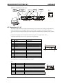
Required Hardware for Operation
Qty
1
1
1
Unit
Axis
System
Axis
1
System
1
1
1
1
1
1
System
Axis
Axis
Axis
Added axis
System
Model #
DCB-274
User defined
SIN-7
or
SIN-8
or
SIN-10
BLC-38
BLC-44
BLC-50
BLC-51-3
TERM-2
Description
Driver-Controller Board
+24 to 40Vdc power supply
RS-232 serial adapter (single axis)
RS232/RS422 serial adapter (multi-axis)
Intelligent serial adapter (Windows 2000/NT)
7 pin home/limit mating connector (included)
6 pin mating motor connector (included)
12 pin mating I.O. connector (included)
Interconnect cable, Cat5 (3 ft.)
Terminator plug (included with SIN-8 or SIN-10)
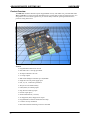
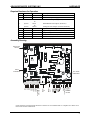
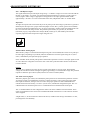
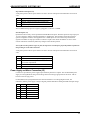
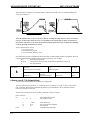
Assembly Drawing
BAUD RATE
SELECT
PORT 4
CONFIGURE
GND
+24-40 VDC
PH2B
PH2A
PH1B
PH1A
VIO
SERIAL
OUT
SERIAL
IN
P1
P2
P3
P4
P5
GND
+5V
JOG 2
JOG S
JOG 1
STEP/ENC. A
DIR./ENC. B
PLC MODE
CONFIGURE
MOTOR
Unless otherwise specified clamp diodes D-1 and D-2 are not installed. Refer to “Output Ports” further on in
this section for more information.
3
ADVANCED MICRO SYSTEMS, INC.
HARDWARE
Out of the Box – Quick Start
The DCB-274 is supplied with mating motor, power supply and I/O connectors. The SIN-(n) (chosen serial
adapter) is supplied with a mating cable and terminator, if required.
Equipment Check List
1. A computer with available serial port.
2. Installed serial communications software such as Hyper term, EASI, ProComm, etc. (EASI works
with DOS).
3. A DCB-274.
4. A SIN-(n) serial adapter (SIN-10 recommended).
5. A +24* to 40Vdc power supply with adequate output power.
6. A compatible stepper motor.
7. A DC Amp meter with bridge rectifier circuit.
8. A cooling fan or heat sink as necessary.
* The DCB-274 will operate at voltages of 12Vdc minimum, but it is not recommended due to the lower
performance and higher power supply amperage demand.
Preliminary Settings
-SIN-7 or 9 (non configurable)
or
-SIN-8 (place red selector switch in “S” (single) position)
or
-SIN- 10 (all (8) switches in off position- towards DB-9 connector).
-DCB-274: Remove any baud rate jumpers.
Basic Set-up
1. Connect the SIN-(n) adapter to serial input (J2) of DCB-274 with RJ-45 cable.
2. Connect the SIN-(n) DB-25/9 end of the serial adapter to the computer RS-232 serial port.
3. Connect your power supply to the power connector (J5). J5-pin 1 is negative (GND). J5-pin 2 is
positive (+) VMM. Improper power connection will destroy the electronics. GND is also connected
to the base plate
(Motor connection is not necessary at this time).
Configure Serial Communications
Full duplex, 9600 baud, no parity, 8 data bits, 1 stop bit.
Note: <CR> is the enter key.
Apply Power
Less than 0.1 amp is drawn (for metered supplies).
Depress the SPACE BAR key and the DCB-274 should sign-on.
Troubles
1. Nothing happens:
a. Check connections.
b. Check for correct COM port.
c. Check switches.
d. Inspect RJ-45 connectors for bent contacts.
2. Garbage characters appear:
a. Verify baud rate and serial parameters.
b. Check the RJ-45 connectors/cable ground continuity.
3. “GO-SS conflict” message appears on screen.
a. Make sure the three-pin PLC jumper is in the standard mode (pins 1 and 2 installed).
4
ADVANCED MICRO SYSTEMS, INC.
HARDWARE
After Sign-on
Enter X<CR>
The parameters are displayed. The last characters displayed will be “n= “ followed by the axis “name”
character, usually “A.” To change the name:
1. Turn off power, allow discharge.
2. Turn on power.
3. Depress the desired “name” key, for instance “B.”
4. Depress the SPACE BAR. The DCB-274 will sign-on.
5. Enter X<CR>. The new name “B” is displayed.
6. Issue the S<CR> (save command). The name is stored in memory.
7. Depress Ctrl-C key (soft reset) followed by the SPACE BAR. Sign on occurs.
8. Enter X<CR> to double-check the name.
Connect the Motor
Set the motor current off (especially if your motor is small and low current model) using the “Y” command.
“Y 0”<CR> (windings off)
“S”<CR> (store settings in NV memory)
Turn off the power and allow plenty of time to discharge any capacitor. Use voltmeter if necessary.
Phase
1A
1B
2A
2B
J5 Pin
6
5
4
3
Signal
Winding 1
Winding 1
Winding 2
Winding 2
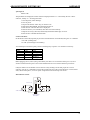
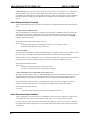
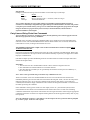
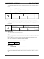
Before plugging into J5, insure (using a ohm meter), that there is a low resistance from pin 5 to 6, and a
similar resistance between pins 3 and 4. There should NOT be a low resistance between pins 4 and 5.
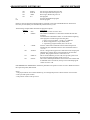
It may be useful to use an ammeter circuit. This will verify winding currents and proper drive circuit
operation. Use the “Y” command to increase the current from zero to the correct amount (1 to 100% of full
scale). With a 4-amp drive, “Y 25 50” equals 1-amp hold current and 2 amps run current.
Dual Ammeter Circuit
Stepper Motor
MDA-990-3 (TYP)
Shunt
-
-
-
-
4 AMP DC Meter
Phase A Phase B
Driver Outputs
5
ADVANCED MICRO SYSTEMS, INC.
HARDWARE
“Do’s, Don’ts and Important Notes”
•
•
•
NEVER connect or disconnect motor wires while power is supplied.
When using a 6 lead motor be sure to insulate/isolate unused wires.
The physical direction of the motor with respect to the direction input will depend on the
connection of the motor windings. To reverse the direction of the motor with respect to the
direction input, switch the wires on phase 1 or phase 2 of the outputs.
**************** WARNING ********************
LIVE CONNECTING/DISCONNECTING MOTORS WILL CAUSE DAMAGE THAT IS NOT COVERED BY
WARRANTY.
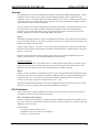
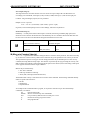
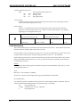
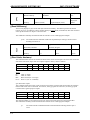
Serial Interface (J2, J3)
Two (RJ-45) connectors provide a loop-through connection, facilitating multiple axis systems. This “minidrop” network allows for a single ASCII character “name” to be assigned and stored in the integral nonvolatile memory of each axis during the setup procedure.
Pin
1
2
3
4
5
6
7
8
Signal
J2-1
GND
RXTXTX+
RX+
5V
Party
J2
Comment
Not used
Power Gnd
+Data in
+Data out
-Data out
-Data in
Power for serial adapter
Enable party line or single
Pin
1
2
3
4
5
6
7
8
Signal
J3-1
GND
RXTXTX+
RX+
N/C
Party
J3
Comment
Not used
Power Gnd
+Data in
+Data out
-Data out
-Data in
Not used
Enable party line or single
All signals on J2 and J3 are interconnected; the 5-volt power is only supplied to J2 – 7. The 5-volts is
intended to power an AMS serial adapter.
There are three types of serial adaptors available.
1. SIN-7 (DB-25), SIN-9 (DB-9). These are passive adapters that allow a basic RS-232 interconnect,
suitable for single axis usage. Party line is not possible with the SIN-7 or SIN-9. Daisy chain
protocol is possible but not recommended.
2. SIN-8 (DB-25) includes an RS-232 to RS-422 converter. A switch selects single or party line mode
for up to 32 axes (includes terminator plug). Proper handshake must be implemented in your
computer for successful party line operation.
3. SIN-10 (DB-9) is a microprocessor-based adaptor that features a dual UART, RS-232 to RS-422
converter at different baud rates and character buffers. The necessary handshake is built in, thus
the sometimes expensive and time-consuming software interface is avoided. The serial
communications is full duplex at 9600 baud. Operation at special 470k baud is possible.
If you have not chosen the SIN-10, the proper handshake MUST be implemented in the host computer to
avoid loss of characters. This protocol is “echoed” characters. If your operating system or application
software is not capable of character-by-character transmission, a SIN-10 is probably necessary. If system
production cost is the priority, the additional system programming effort to implement a SIN-7, 8 or 9 may be
cost effective. A complete description of the serial interface specifications and operation is contained in
Section 2, “Serial Interface.”
6
ADVANCED MICRO SYSTEMS, INC.
HARDWARE
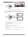
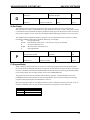
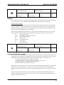
Multi-axis Serial Interface Connection
BLC-51-XX
INTERCONNECT
CABLE
SERIAL
INTERFACE
ADAPTER
SERIAL IN
SERIAL OUT
TERMINATOR
PLUG
J2, J3
Pin 1
SIN-8
OR
SIN-10
DCB-274 #1
DCB-274 #”N”
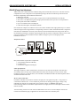
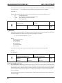
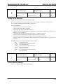
I.O. Connections (J1, J4)
The DCB-274 has a robust set of input and output signals. Two connectors (J1 and J4) provide dedicated
inputs and outputs. Five user-defined signals are also provided. All inputs can withstand voltages in
excess of +28 volts. Two high-voltage, high-current outputs are available to drive solenoids, relays, motors,
etc.
Fourteen input signals can be configured as either sourcing or “PLC” inputs. Thus, many
controllers/sensors that provide “true” outputs are easily adaptable.
Description
Input
Input
Input
Configurable output or input
Output
Power common
Vcc – logic power
Input
Input
Input
Input
Input
J1
Pin 12
Signal
Port 1
Port 2
Port 3
Port 4
Port 5
Gnd
+5v
Jog-1
Jog-Speed
Jog-2
Step or Encoder A
Direction or Encoder B
Pin 1
(J1)
Pin
1
2
3
4
5
6
7
8
9
10
11
12
Note: Outputs are 5-volt logic with 10k pull up to 5 volts.
Description
Home input
Limit A input
Limit B input
Go input
Soft Stop input
Gnd
VIO
Used with the F[ind] home command
Inhibits motion in + direction only
Inhibits motion in - direction only
Start stored program sequence at location 0
Stop stored program sequence
System power common
+4.5 volts out or VIO input
J4
Pin 7
1
2
3
4
5
6
7
Signal
Pin 1
(J4)
J4 Pin
7
ADVANCED MICRO SYSTEMS, INC.
HARDWARE
Pin 7 - VIO Reference Input
This signal defines the input and output voltage range. A “default” voltage of 4.6 volts is derived from the
internal +5-volt supply, via a diode. Any external load must be limited to several mA. You may apply an
external, higher “VIO” voltage, if appropriate to the application. The input signal thresholds will be
approximately ½ of VIO or 2.3 volts. The threshold is the same, independent of PLC or “normal” mode.
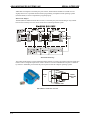
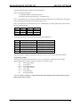
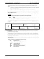
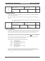
Input Ports
All inputs incorporate 10k resistors that may be set as pull-up to the VIO voltage or pull-down to ground as
defined by the three-pin “PLC” jumper. When the jumper is in the “PLC” position, (pins 2 and 3 installed)
the resistors pull-down and maintain a zero volt level on the inputs. All these inputs will withstand 28 volts
DC, even if a lower VIO voltage is used. The possible inputs include; (J1)- ports P1, P2, P3 and P4
(selectable), Jogs (3), Step and Direction and (J4)- Home, Limits (2), Go, and Soft Stop. VIO becomes
especially important where outputs drive high voltage devices.
PIN 1
Standard Mode- Sinking Inputs
When the PLC jumper is in the standard mode position (pins 1and 2 installed) the resistors act as pull-up to
the VIO supply. Depending on your mode, software commands to invert the signals using the ”l” (lower
case L) command may be required for proper operation.
In the “standard” mode, the 10k pull-up resistor will become a pull-down resistor as the input signal exceeds
4.6 volts. When the voltage does exceeds 4.6 volts it will cause a pull-down affect because of the internal
resistance divider.
Example
When 28 volts is applied to an input, the drive current will be about 0.7 mA per signal. The threshold
voltage will increase as each 28-volt signal is applied, approaching 8.5 volts when all are high. The preferred
input drive method is open collector (drain) transistor or switch to common (GND).
PLC Mode- Sourcing Inputs
When PLC jumpers (pins 2 and 3) are installed, the pull-up resistors are transformed to pull-down resistors.
Activating an input is accomplished by asserting a voltage exceeding ½ VIO on the given input. When
these inputs are held low, the logic sense is inverted. For proper operation a mode command must be
entered and stored in NV memory. Use the “l” (lower case L) command to configure the inputs. The “l 9”
command will invert all of the inputs. The “l 8” command will invert all but the limit switch inputs.
The “l” command defines several configurations. Please refer to the command section for details. These
inputs can withstand in excess of 28 volts. The default threshold will remain at 2.3 volts unless an external
VIO is supplied.
A higher VIO (i.e., 24 volts from a PLC with 24 volt drivers) would increase the logic threshold to 12 volts,
providing better noise immunity.
8
ADVANCED MICRO SYSTEMS, INC.
HARDWARE
+5 Internal Power Supply
5V
Pin
4.6 - 30 Vdc
VIO
VIO
Pin
10k
+
PLC
Signal
VIO/2
STD
CPU
10k
1
2
3
STD
Signal
Comparator
10k
Input
Pin
PLC
To other comparators
GND
Pin
Connector
Typical User Input Circuit
(Step, Direction, Ports 1, 2, 3, 4 (used as an input), Jog (3), Limits, Home, Go and Soft Stop)
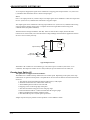
Output Ports
Two user output ports are provided on the DCB-274 with a power FET output circuit capable of sinking up
to 2 amps DC. They cannot be converted to a sourcing mode. If a source signal is necessary, a relay should
be installed.
The outputs DO NOT include clamping diodes attached to VIO. There is provision for diodes (D1, D2) on
the board .If these diodes are installed; VIO MUST BE EQUAL TO OR HIGHER THAN THE DEVICE
POWER SOURCE VOLTAGE. If a 24-volt solenoid valve is to be driven, the VIO input must be at 24 volts.
Because VIO also defines the logic input levels, this can be a problem. If your design is to drive inductive
loads such as relay or motor coils, you must implement external clamp diodes as required. R3 and R4 should
also be removed.
ANY O F THESE MODIFICATIONS MUST BE PERFORMED BY TECHNICALLY QUALIFIED PERSONNEL.
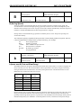
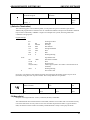
Port 4 (Configurable user port with JP1 and JP2)
This port can be configured as either an input port (as described above) or an output port.
Port 4 defined as:
Input
JP1
2-3
JP2
Yes
Output
1-2
None
Comment
Reference “l 16” (lower case L)
command in the software section.
PIN 1
VIO
+
Load
Optional Clamp
-
Comparator
SMC-26
Microprocessor
JP-2
VIO/2
3
JP-1
I/O Connect
1
Mosfet
Port 4 Input / Output Circuit
9
ADVANCED MICRO SYSTEMS, INC.
HARDWARE
As an output (as shipped) the signal can be redefined as a stepping pulse output with the “l 2” (lower case
L) command. This also defines P5 as a direction output signal.
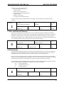
Port 5
Port 5 is an output port/driver, rated at 2-amps. The output signal can be redefined as a direction output with
the “l 2” (lower case L) command. Port 4 becomes a step pulse output.
The output signal can be redefined as a moving output with the “l 4” (lower case L) command. The moving
output is useful in designs where a PLC or computer cannot interrogate motion status using serial
communications (the preferred method).
The FET transistor ratings are RDSon=.065 ohm, VDS= 55-volts and ID=17 amps (because the FET
transistors are not heat-sunk, never draw more than 3 amps) Damage caused from miss application of these
devices is not covered by warranty.
VIO
+
Load
Optional Clamp
Output Pin
SMC-26
Microprocessor
Buffer
Mosfet
Typical Output Circuit
The default “off” condition is non-conducting (5-volts) when a port is turned on (such as the “A 16”
command). The output will conduct to zero volts (Ground) at up to the rated current of 16 mA, DC.
Encoder Input Option (J1)
This option does not support “Encoder Feedback”
The DCB-274 is available with step and direction or encoder inputs. Depending on the option, either step
and direction or optional encoder phase A and phase B can be used. Several features and cautions must be
observed.
1. The position counter will follow the input step/direction (or A/B) inputs.
2. The limit switches function, with direction sensitivity.
3. The minimum pulse low time is 7 microseconds.
4. Stepping occurs on the rising edge of the pulse.
5. The direction must be setup prior to the rising step edge.
6. Direction must be held for >10 microseconds after the rising step edge.
7. Motion commands will conflict with these inputs.
8. The maximum step rate is 16,000* pulses per second.
*Higher step rates may be possible on some products. Contact AMS for details.
1 0
ADVANCED MICRO SYSTEMS, INC.
HARDWARE
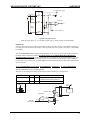
Step and Direction Inputs (J1)
A 10k pull-up resistor allows open-collector circuits to be used. The inputs will withstand in excess of 24
volts.
Pin
6
11
12
Signal
Ground, common with the power supply input
Step pulse input
Direction input
The recommended step input is a negative going pulse 5 volt TTL or CMOS.
Encoder Inputs (J1)
Optional encoder circuitry can be specified with the DCB-274-E option. With this option the step input pins
11 and 12 change to industry standard quadrature A and B inputs. The quadrature clocks derived from
optical or magnetic encoders, when applied to the A and B inputs are converted to step and direction
signals. The number of steps per encoder revolution is equal to four times the number of “slots” on the
encoder. The motor will directly follow any changes in the encoder position.
Note: If the encoder produces steps too fast, the step motor can stall if it is physically unable to follow the
abrupt changes in rate and/or direction.
A 10k pull-up resistor allows open-collector circuits to be used. The inputs will withstand in excess of 24
volts.
Pin
6
7
11
12
Signal
Ground, common with the power supply input
5 volts. Can be used to power an encoder with
low current requirements.
Encoder Phase A
Encoder Phase B
Power Supply and Motor Connection (J5)
Connector J5 provides the power supply input and motor phase drive outputs. The recommended power
supply is an unregulated DC design with voltage and current ratings, appropriate for the driver. The onboard 5-volt is for logic power.
For maximum motor speed performance the motor should have a low voltage (higher current, low
inductance) and the power supply voltage as high as possible NEVER exceeding the DCB-274 input ratings.
Pin
1
2
3
4
5
6
Signal
Gnd
VMM
PH-3
PH-2
PH-1
PH-0
Type
Ground
+24 to 40Vdc
Phase 2-B
Phase 2-A
Phase 1-B
Phase 1-A
1 1
ADVANCED MICRO SYSTEMS, INC.
HARDWARE
High Torque
6
5
PH-2 4
PH-3 3
VMM 2
GND 1
PH-0
PH-1
+ Power
- GND
Bipolar Series
FIG A
High Speed
6
5
4
3
2
1
+ Power
- GND
Bipolar Parallel
FIG B
High Speed
6
5
4
3
2
1
+ Power
- GND
Bipolar 50% Copper
FIG C
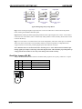
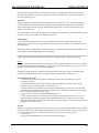
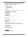
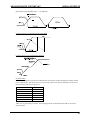
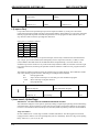
Typical Wiring Diagrams for Step Motors
Fig. A: Series winding for higher torque and lower current. The inductance is 4 times that of the parallel
mode, reducing the maximum obtainable speed.
Fig. B: Parallel winding for better high-speed performance but requires higher drive current. A 4-wire motor
is the same as an 8-wire motor, but it is connected (in either parallel or series) internally. Some motors can be
rewired at the factory.
Fig. C: A 6 wire motor is a variation of the 8 wire series configuration, where the “center taps” are available.
The 6-wire motor can be used in series mode but cannot be connected in parallel. A compromised 50%
copper connection can be used, producing higher speed with reduction of torque.
Note: NEVER connect or disconnect the motor when the power is “ON”. Wait at least two minutes after
turning off the power before connecting or disconnecting the motor. This will allow proper dissipation of
voltage from the unit. Failure to do so may cause damage and void the warranty.
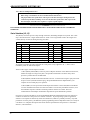
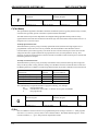
Baud Rate Jumpers (B1, B2)
Jumpers B1and B2 determine the baud rate. Standard UART properties are no parity, 8 data bits, 1 stop bit.
B1
N
Y
N
Y
1 2
B2
N
N
Y
Y
Baud Rate
9600
460k
38.6k
19.2k
Comment
Factory setting N, 8, 1
Requires SIN-10 serial adapter
ADVANCED MICRO SYSTEMS, INC.
HARDWARE
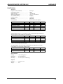
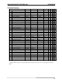
Specifications
Electrical
Output Current (maximum)……………….
Chopping Frequency...................…………...
Supply Voltage............................…….…….
Motor Step Resolution..............…………….
Non-Volatile Memory.............……………...
Position Counter..........................…………..
Baud Rate..................................…….……...
Serial Interface……………………………...
Signals
RX, TX
High Input Voltage
Line Input Current
Party Select
External Terminator
*Threshold
4.0 Amps
20kHz
+24 to 40 Vdc
1/8,1/4,1/2, Full, Wave
2k Bytes
±8,388,607
9600, 470k
RS-422 4-Wire, Full Duplex
Min
-7
-0.8
-.3
Typ
5
2
2.5*
220
Max
12
28
1
36
Units
Vdc
Vdc
mA
Vdc
Ohms
J1 Input Signals: Ports 1, 2, 3, P4_In, Jog 1, Jog 2, Jog Speed, Step and Direction
J4 Input Signals: Limits, Home, Go and Soft Stop
Signals
Min
Typ
Max
Units
VIO Supply (J3-7)
4.6
28
Vdc
Threshold
2.3*
½ VIO
Vdc
Input Voltage
-0.3
28
Vdc
Input Current
0.5*
VIO/10
2.8
mA
* VIO = 4.6 volts using internal supply
J5 Output Signals: Ports 4_Out and 5 (open drain with 100k pull-up’s to VIO)
Clamp diodes are required for inductive loads.
Output Signals
Min
Typ
Max
Units
Outputs Ports 4 and 5
0.7
28
Vdc
Output Current (sink)
2
Amp
Environmental
Storage...………. -45 to 85 Degrees C
Operating.....…... 0 to 55 Degrees C
Humidity.......….. 0 to 95% (non-condensing)
Physical
Size (in.)………... 5.2 x 4.13 x 1.4
Weight........…… 8 oz.
1 3
ADVANCED MICRO SYSTEMS, INC.
HARDWARE
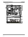
Physical Dimensions
Heat sink mounting bracket
0.75
0.22
2.50
4.13
12 PIN I/O
SERIAL
IN
SERIAL
OUT
0.75
7 PIN 1/O
PWR / MTR
4.70
5.20
1.38
0.75
SLOTS ACCOMODATE 10-32 MOUNTING HARDWARE
NOTE: ALLOW 0.5 INCH CLEARANCE ON ALL CONNECTORS FOR EXTERNAL WIRING
1 4
ADVANCED MICRO SYSTEMS, INC.
SERIAL INTERFACE
Overview
This Application covers the serial communication design for ADVANCED MICRO SYSTEMS, INC. (AMS)
intelligent control products. These products include complete packaged systems, OEM boards, subassemblies, and I.C.’s. The basic design has remained constant over 20 years. All AMS products are based
on the same core micro-controller family, which contain two-way serial communication using the standard
ASCII characters used in virtually all computers.
Only two signals are used, TXD (transmitted data) and RXD (received data). The hardware interface for the
two signals is one of two industry standards, either RS-232 or RS-422. These standards describe the
physical wire layout and signal voltage swings. The brief descriptions here are those relevant to AMS
product communications and do not include DTR, DSR, CTS, RTS, etc.
RS-232
Introduced in 1962, RS-232 has been widely used throughout the industry. This single ended transmission is
useful only for short distances. The connector is either a 9 or 25 pin “D” connector. RS-232 includes a 3-wire
interface using RXD, TXD and ground.
Typical voltage swings are –12 volts to +12 volts. The relatively high impedance and low speed limit both
baud rates and wire length. In non-hostile environments and limited distance communications it will operate
with 0 to +5 volt swing.
RS-232 can operate with one serial driver and one serial receiver at a maximum of 20k baud. For serious
designs (even with one axis) we recommend the RS-422 mode of operation.
Stand-alone Operation
All AMS controllers include “non-volatile memory” to hold program sequences that, once inserted, can be
triggered at power up via a switch closure or pulse input. Since the purpose of the serial interface in this
application is only to enable insertion of the command sequences, RS-232 is adequate.
RS-422
RS-422 is a newer transmission system that incorporates a 2 wire per signal differential standard that is faster
and useful at up to 400 feet at 1M baud or 4,000 feet at 100K baud. This 5-wire signal, full duplex interface
includes RX+, RX-, TX+, TX- and Ground. This system is capable of driving up to 32 receivers (motor
control axis) on a single “drop” bus. Voltage swings are 0 to +5 volts.
While not recommended, the RS-422 line receivers will withstand RS-232 levels. RS-232 receivers work with
the lower 5-volt swing, permitting both single ended and differential operation.
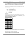
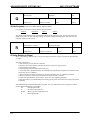
RS-232 Hardware
There are two ways to configure AMS RS-232 products. The basic connection is single axis mode with a
straight RS-232 connection using a SIN-7 serial adapter.
SIN-7 / SIN-9 RS-232 Serial Adapter
The SIN-7 is a DB-25 to RJ-45 adapter for single axis, RS-232 communication applications. The SIN-9 is a 9pin version. These converters facilitate connection between a standard computer “D” connector output and
AMS’ RJ-45 connector inputs.
Features include:
• Connects computer or terminal to axis
• Standard 25 pin or 9 pin connector for COM port
• Passive - no power required
1 5
ADVANCED MICRO SYSTEMS, INC.
SERIAL INTERFACE
SIN-7
RS-232
Computer
DB-25
2
3
5
1,7
TXD
RXD
CTS
GND
3 TX4 RX1 MVG
2 GND
6 DST
20 DTR
Single axis, RS-232 connection using AMS SIN-7 adapter
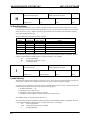
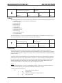
The other method, called “daisy chain,” is for multi-axis applications and is NOT recommended by AMS.
Daisy chain is accomplished by interconnecting one or more axis in “series.” Here, the TXD output of the
first axis is connected to the RXD input of the next axis, etc., with the last axis TXD connected to the RXD of
the computer.
SIN-7
RS-232
Computer
DB-25
2
3
5
1,7
TXD
RXD
CTS
GND
6 DST
20 DTR
3 TX4 RX1 MVG
2 GND
3 RX4 TX\
AMS RS-232 controller “Y”
RS-232 “Daisy Chain” connection
Advantages of this configuration include:
1. Dynamic addressing (the axis address is assigned at each initialization) and do not have to be preassigned or stored in NV memory.
2. Lowest cost because, RS-232 adapters are passive, without any electronics.
Disadvantages:
1. RS-232 is less reliable than RS-422 and is more susceptible to noise.
2. Multiple axis RS-232 configurations are difficult to analyze.
3. Complex wiring.
A single axis RS-232 system will operate well and is easy to implement. Multiple axis daisy chained systems
are not recommended.
The AMS demo program (“EASI”) does support daisy chain and single axis RS-232 mode.
1 6
ADVANCED MICRO SYSTEMS, INC.
SERIAL INTERFACE
RS-422 (Party Line) Hardware
AMS “Party Line” communication is an RS-422 design that uses RS-485 rated circuits. This interconnect is
comparable to a LAN configuration. The hybrid design merges the best of both EIA specifications and
maintains compatibility with EIA RS-422 and features:
• Multi drop serial bus
• Full duplex connection; receive data is one pair of wires and transmitted data a second pair.
• Zero to five volt differential signals for high speed and robust noise rejection over long distances
• Data speeds from 100K to10M Baud
• Up to 32 controllers from one COM port
• Cable network length to 1200 Meters (4000 ft)
One master host computer can address a device (axis) with a command. The single packet of up to 15 ASCII
characters begins with a single character corresponding to the axis “name” and terminated with a single linefeed character. Handshake is necessary and is based on each transmitted character being echoed. Prior to
the terminating LF character, numbers representing data such as position or limit status will be received. The
protocol is similar to other manufactures but is different enough to prevent co-mingling of other
manufactures devices.
Party Line Connect
AXIS A
AXIS B
AXIS “n”
COMPUTER
SERIAL ADAPTER
TERMINATOR
RS-422 “Party Line”
Party line hardware requires three components:
1. A serial adapter (RS-232 to RS-422),
2. A cable(s) and
3. A terminator (supplied with adapter).
Cable Specifications
Although 8-conductor (with 8 contact RJ-45 connectors at each end) flat “telephone” cable has been
successfully used in the past, the recommended interconnect cable for party line use is UTP 24 AWG..
twisted pair (category 5) network cables, now available as standard from AMS. The older telephone cable is
suitable for RS-232 or lab work.
Device (Axis) Connection
Each motor controller has two RJ-45 connectors for party line. All signals except the +5 volt power are
connected in common. The +5 volt is isolated to prevent “back” feeding power supply voltage to any
individual axis with the AC switched off or power removed. Thus, it is IMPORTANT that the
interconnecting cables travel from the output connector (on right) of one axis to the input connector of the
next axis (on left).
Two terminating resistors are used on the last differential line receiver. The serial adapter contains one
resistor and a terminator plug is supplied to be used on the LAST axis in the Party bus.
1 7
ADVANCED MICRO SYSTEMS, INC.
SERIAL INTERFACE
AMS offers two adapters to facilitate party line connect; models SIN-8 and SIN-10. The SIN-10 costs
slightly more but is so powerful that the software programming is simplified. Some operating systems
(Windows 2000) are close to impossible to program properly.
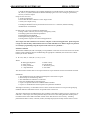
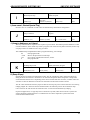
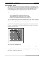
SIN-8 Serial Adapter
The SIN-8, RS-232 to RS-422 serial data converter, is used with party line network designs. Any number
between one and thirty-two axes can be connected in a mini-drop network system.
RS-422/485 BUS-drop
The bi-directional adapter is powered from the AMS controller. A switch is provided to select the single-axis
mode in order to assign the required axis "name" character. The serial communication requires a "character
by character" handshake protocol that may not be practical with all computer operating systems.
RS-422 LOGIC
RS-422
PARTY LINE
OUT
RS-232
IN
PARTY
SINGLE LINE
SIN-8, RS-232 to RS-422 converter
1 8
ADVANCED MICRO SYSTEMS, INC.
SERIAL INTERFACE
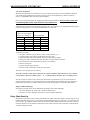
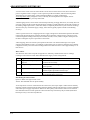
SIN-10 Intelligent Serial Adapter
The SIN-10 is an intelligent serial line converter that simplifies application software development and
improves overall performance. Dual, independent UARTS (COM ports) permit spooling commands at rates
between 1200 and 115k baud. Specific operating instructions are contained in the SIN-10 Users Guide.
The SIN-10 has a built-in microprocessor that offers a number of features:
• Emulating the SIN-8
• Diagnostic LED’s
• Numerous Input baud rates
• Output (party line) baud rates – including the special 470k baud rate
• DB-9 serial input connector
• RJ-45 party line connector
• 5 volt powered from controller
• 250 character buffers for multiple commands per line
Because the SIN-10 eliminates the need for special echoed character software it can be used in Windows
applications where either the machine or software is slow and/or the operating system prevents direct
programming of input or output instructions.
RS-232 DATA LEDS
PARTY DATA LEDS
CTS
MOVING
DSR
PARTY
SELECT
TXD
RXD
UART
1
256 CHAR
RECEIVE
BUFFER
256 CHAR
RECEIVE
BUFFER
CPU
PARTY LINE
DATA
UART
2
DB-9
5V
GND
BAUD AND MODE
SWITCH
RJ-45
SIN-10, intelligent serial line converter
There are several commands that the SIN-10 can execute including: “Scan for axis present” (required
initialization) and “Wait until motion complete” (1 or all axis). A typical command string to a X-Y- Z system
could be:
X+1000;Y+1000;Z+1000;9W*;XZ;YZ;ZZ
This would cause all three axes to move the specified number of steps; wait until motion is stopped then
read back the three positions.
Other Party Line Signals
In addition to the serial data bus wires several other signals exist in the AMS party line interconnect.
1. GND (pin 2) Ground is common for all devices (axis). All power supply commons are connected to prevent
high common mode voltages. Please note that the power common is generally connected to the case return.
2. +5 Volts (pin 7) is available to power the serial adapter (SIN-8 or SIN-10) from the first axis.
3. MVG Not available in this product. Software pooling must be used to query motion.
Note, The SIN-10 determines motion via special SIN-10 instructions.
1 9
ADVANCED MICRO SYSTEMS, INC.
SERIAL INTERFACE
4. Party Select (pin 8). Each axis tests this input after reset (power up or in response to a ^C command) to
determine either single or party line mode. Single mode (ONLY one axis connected) is used for debug,
programming for stand-alone use or assignment of party line “name”. The SIN-8 has a switch to manually
select party line (P) or Single (S) mode. The SIN-10 is selectable via host commands or a built in mode
switch.
Serial Communications Overview
There are three methods (protocols) used to send and receive command and data from an AMS controller
(axis):
1. Simple “Dumb” Communications
This is accomplished by connecting one single axis to the computer. Commands can be typed in and the
controller will execute them. The designer can also enter program sequences into the NV memory and
execute them. Virtually every capability can be explored. It is a “human friendly” interface and NEVER a
computer controlled operation.
Serial adapters used: SIN-7 / SIN-9, SIN-8, or SIN-10.
At start-up:
1. If using a SIN-8 or SIN-10 serial adapter, make sure it is in “single-line” mode.
2. Hit the SPACE BAR key to sign on after reset.
2. Party Line Mode
Party line mode is intended for computer-controlled designs. A computer (usually a PC) can address one or
more axis using a “mini drop” network implemented with CAT-5 network cable with RS-422/485.
Between 1 and 32 axis are configured as “slaves.” Unlike the “Dumb” mode, a proper character by character
echoed protocol is necessary for proper operation. The SIN-10 adapter will simplify this protocol.
Serial adapter used: SIN-8 or SIN-10.
At start-up:
1. Make sure the serial adapter is in “party line” mode.
2. The host computer interrogates and records axis name(s).
3. Daisy Chain Mode (not recommended for more than 1 axis)
This older protocol is similar to the party line mode but RS-232 protocol is used. Because it involves special
wiring of RXD to TXD signals, it should only be used with a single axis design. When multiple axis are
implemented they are less reliable, communication speeds are slower and troubleshooting is difficult.
The only advantage is that the name can be dynamically assigned by the host computer on power up
sequence and the computer protocol can be implemented with the lowest cost RS-232 adapters.
Serial adapters used: SIN-7 or SIN-9.
At start-up:
1. The host computer emits axis #1 name, receives ending axis name +1.
Serial Communications Software
Today’s computers are mostly a derivative of the IBM PC. Almost all of these computers include at least
one serial RS-232 connection. For those without “COM” ports, low cost serial cards are available.
For many years PC’s have used DOS as the basic operating software. In recent years however, Windows
has replaced DOS in many applications. So, the system designer must make choices about the application
requirements.
2 0
ADVANCED MICRO SYSTEMS, INC.
SERIAL INTERFACE
Operating systems like Windows NT and Windows 2000 prevent programmers from direct access of the
hardware. The programmer is forced into passing instructions via “mail-boxes” to perform I/O functions, a
slow and inefficient process.
Baud Rate
AMS has introduced a number of motion control products over the last 20+ years. The software for serial
communications has remained essentially unchanged. Depending upon the controller I.C. and hardware
design, different baud rates are possible. The DCB-274 supports 9600, 38.4k and, with the SIN-10 serial
adapter, a fast 470k baud.
The standard default baud rate for all AMS products is factory set to 9600 baud. . Serial data format is 8 bits;
1 start bit, 1 stop bit, and no parity; the default for most PC’s.
EASI Software
To assist with the implementation of your project, AMS offers a software program called EASI. This
software has evolved over a 20-year period and will operate under DOS, Windows-95 and Windows-98 (as a
DOS application).
With a SIN-7/SIN-9 and SIN-8 adapter, EASI will function running under DOS, Windows-95, Windows-98. It
is reported that Windows-ME and NT are also compatible.
EASI does have limitations, especially with Windows-2000. The GUI operation (pull down menus, party line)
is NOT compatible with Windows-2000 and is limited to “DUMB Terminal” operation in this mode.
SIN-10
The SIN-10 serial adapter can function in an “intelligent” mode or emulate a SIN-8 for test purposes. When
in the SIN-8 mode, full GUI is possible with any of the above-mentioned operating systems, but you will be
defeating the purpose of the powerful SIN-10 capabilities.
In addition to EASI, almost any communication program, such as ProComm, or Hyper Terminal can also
perform the dumb terminal operation, provided the necessary character filter is configured.
Serial Interface Using EASI
1. Attach the “D” connector end of the serial adapter to either COM1 or COM2 of your PC/AT
compatible computer.
2. Connect the other end of the cable assembly (looks like a telephone connector), to the mating
connector J2 ”Party Line Serial Input”, on the AMS device.
3. Install a terminator plug (TERM-1) into J3 “Party Line Serial Output” of the last axis. The controller
will work without a terminator plug, however reliability may be compromised, based on the environment
(noise) and length of the interconnect cables.
4. Apply power to the device. (Reference Hardware Section).
5. Install the diskette and type: EASI<CR> at the prompt. At the opening screen enter “n” if you are
operating from a monochrome terminal or hit the ENTER key for color. Use the arrow keys to select
COM1 or COM2. COM1 is the default setting. Follow the same procedure to select the correct baud rate
(9600 BPS is the default setting).
Sign-On
Single axis mode must be used for name assignment. Any terminal software, including EASI “dumb terminal”
can be used. When using a SIN-8 make sure that the RED switch on the side of the connector is in the single
(S) line mode. When using a SIN-10 make sure the party line switch (S8) is in the off position.
1. Start easi.exe.
2. Select the “DUMB TERMINAL” mode. A blank window will appear.
2 1
ADVANCED MICRO SYSTEMS, INC.
SERIAL INTERFACE
3. Strike the SPACE BAR key. The controller should sign on with the software version number Vx.xx. If
not, enter a (^C) (Reset) and strike the SPACE BAR key again. The “reset” message is generated by
easi.exe, not the axis output.
If sign-on does not occur:
a. Verify all connections.
b. Insure that the SIN-8 or SIN-10 is in the “single” mode.
c. Check your comport set-up.
..
4. Striking the ENTER <CR> key should result in an echo of “# “ characters, further indicating
communication is established.
In single mode, you can do a number of useful things:
• Assign “name” character (not necessary if using daisy chain)
• Tweaking speed and acceleration parameters
• Experimenting with commands
• Development of program sequences
• Storing motion sequences for non-hosted applications
Note: Single axis mode should never be used in a computer or PLC hosted applications. If the design has
a single axis then the daisy chain method can be used with either RS-232 or RS422. Single axis functions
are suited for programming using the keyboard with visual screen “feedback.”
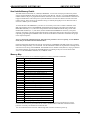
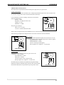
Examine Command
The Examine command (X)<CR> will display a set of parameter values that were last stored into non-volatile
memory. These parameters may be modified using the appropriate commands, then stored in non-volatile
memory as the new “defaults.”
X K= 5/5, I= 802, V= 10370, D= 1, b=30, s, ¼, n=A
Where:
K= Ramp up/ramp down
V= Slew velocity
b = Decay Threshold
¼ = Step Resolution
I= Initial velocity
D= Divide factor
s= Slow decay (now)
n= Axis name
The values shown assume there are no input connections or special modes such as inverted limit switches.
Some Rules
1. The command line may be edited using backspace as characters are typed.
2. The line may be canceled using <ESC>.
3. The command line is limited to 15 characters.
4. Only one command may be entered per line.
5. A space is optional between the command and first number.
6. A space or comma must be used to separate two parameter commands.
Although not necessary, it is desirable to have a motor connected to the driver. This provides gratifying
feedback. Reference “Hardware Section” for specific motor connections.
The motor characteristics should match the drive capability. If the motor refuses to move in response to an
index like “+1000” steps, the control parameters may not be correct. This stalling manifests itself in partial
movements of the motor shaft and audible sounds. Insure that the load is not too heavy. Tweaking
parameters like motor current, velocities (I and V) and ramp slope (K) can usually coax the motor to action.
2 2
ADVANCED MICRO SYSTEMS, INC.
SERIAL INTERFACE
Axis Name Assignment
Whenever the application is controlled via a “host” computer the proper protocol (handshake) MUST be
used. Either the programmer must write the necessary serial, echoed character-by-character software
(driver), or implement a SIN-10 for the proper handshake.
In any case a unique name must be assigned and stored in the NV memory. EVEN A SINGLE, ONE AXIS
SYSTEM REQUIRES PARTY LINE OR DAISY CHAIN PROTOCOL.
AMS software searches for axis names starting with A, B, C, etc. While X, Y, or Z might be more descriptive,
it can take a longer time to scan. Recommended names are as follows:
Recommended Names:
(Upper case A through Z)
(Lower case a through z)
ASCII
HEX
[
5B
\
5C
]
5D
^
5E
5F
‘
60
Non-valid Names:
ASCII
HEX
^C
03
CR
0D
LF
0A
@
40
Assign the axis name:
1. Reset the controller to cycle power (5 volts) or enter control C (^C).
2. Type the single (case sensitive) name character (once only).
3. Follow the name with a SPACE BAR. The sign-on message will appear.
4. Enter the X<CR> command. The name will show at the end of the echoed line.
5. Issue the S<CR> store command (saves name in NV memory).
6. Reset as in step one.
7. Sign on with the space character.
8. Use the X<CR> command to verify the proper name.
The name is now stored in the NV memory.
Note: The controller will accept any character as a name, including control characters. Two common
error characters show up as either a space ‘ ‘ or ^C (heart symbol). In either case, reset and do it over.
The unit is ready to operate in the current single axis mode or be switched over to party line mode. It is
suggested that the operator use single mode first to become familiar with command input. The single axis
mode can be used with any “dumb” terminal device and is not dependant on using the AMS software.
Simple Command Examples
The single axis mode can be used to familiarize the designer with some commands.
1. Issue the command: “R -1000”<CR>. The motor should move.
2. Issue the “Z”<CR> command. The position (-1000) should be displayed.
Daisy Chain Start-Up
Multiple axes (controllers) may be interconnected directly (daisy chained) using the controller logic levels or
buffered with line driver-receivers. All baud rate settings MUST be the same. Characters are received by the
first controller input (RXD), and then echoed to the next controller (RXD->TXD) in the serial link. The host
terminal/computer receives characters from the last axis (TXD) in the link. The closed loop communications
assures the integrity of data.
2 3
ADVANCED MICRO SYSTEMS, INC.
SERIAL INTERFACE
The initial input sequence MUST be a Line Feed (LF) character followed by a valid “name” character in the
standard ASCII collation sequence. Once the recognized sequence is received, the controller will assume the
name until a hardware reset is made. The first axis in the string will output the Line Feed character followed
by the next higher ASCII character in the character set. This sequence continues until all axes have assigned
names. If the first valid usable “name” character is an upper case “A” the controller will be assigned the
prefix name “A” then output a “B” to the next axis controller in line. Four Daisy Chained axes would then
assume the names of “A”, “B”, “C” and “D.” Sign on messages are NOT generated. The last controller will
respond with a Line Feed and character representing the last name plus one (“E” in this example).
Once the names are assigned (after every reset) the communications is same as party line protocol.
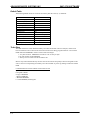
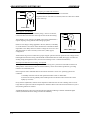
NV Memory Programming
The above examples were samples of immediate commands. The following is a sample sequence used to
store a sequence in the non-volatile memory. Note that when programming, the sequence is immediately
written to non-volatile memory without any additional action required to save it. This example starts at
location “0” of NV memory. Other segments can reside at any free location.
Enter
P0<CR>
Remark
Place in Program mode. Insert instructions at location 00.
Address
0
O0<CR> Set Origin to zero.
1
R10000<CR>
Move 10,000 steps in the “+” direction, relative to Origin.
6
W 0<CR>
Wait until complete.
9
R -10000<CR>
Move 10,000 steps in the “-” direction, relative to Origin.
14
W00<CR>
Wait until complete.
17
J1 3<CR>
Jump to address 1, 3 times.
21
R500<CR>
Move 500 steps in the “+” direction, relative to Origin.
26
P0<CR>
End Program.
Now list the stored program
Q<CR>
Query command.
Verify the Program
The controller will respond with:
0
O
1
R
10000.00
6
W
0
9
R
-10000.00
14
W
0
17
J
1
3
21
R
500.00
26
Execute the Program
Enter
G0 1<CR>
Remark
Programs start executing at location zero. If the Trace option is on, it will display
each instruction prior to execution.
Note: This same program can also be triggered by pulsing the “Go” input and the program can be
terminated at any time by hitting the ESCape key.
2 4
ADVANCED MICRO SYSTEMS, INC.
SERIAL INTERFACE
Edit Program
Example: It is desired to change instruction number 21 from 500 steps to 5,000 steps:
Enter
Remark
P21<CR>
Edit instruction 21.
R5000
Move 5,000 steps in the “+” direction, relative to Origin.
“ESCape”
Terminates Edit mode.
Note: Caution should be exercised when making Program Edits in dumb terminal mode due to
variations in command byte length that may effect subsequent command address locations and possible
corruption of non-volatile memory storage. It is recommended that application programs be developed
using the menu driven program (Party Line selection) in the EASI diskette, which includes a
sophisticated Editor and Compiler.
Party Line and Daisy Chain Line Commands
Note: If a SIN-10 is used in the “intelligent” mode, then the following rules will not apply because the
SIN-10 will perform the necessary handshake.
The SMC series controllers incorporate a buffered UART input, capable of receiving and holding ONE
character at a time. The controller must read this character before another one is received; otherwise the
UART will be over-run, resulting in missed character errors.
The handshake method used is a simple “echo” of the received character. The host computer MUST
ALWAYS wait for the echo.
Fixes such as insertion of delays between characters may seem to work but will ultimately fail. Beware that
many PLC manufacturers do not provide the serial software flexibility required for your application to make
the proper communication.
(The SIN-10 adapter provides handshaking functions and other features to make life simpler and reduce
software development time).
Some Rules
1. The first character of a command MUST be the “name” character assigned to the axis.
2. The command line terminator MUST be a Line Feed character.
3. The name must be preceded by an LF (presumably the terminator for the previous command), i.e.,
<LF>“n” xxxxxxx <LF>.
Note: An LF can be generated using a Ctrl–Enter key combination on a PC.
The first Line Feed “resets” the command buffer for all axes. The controller then tests the character
immediately following a Line Feed. If this character matches the assigned “name,” the axis will interpret the
following characters (up to 12) as an input command. If the axis does NOT detect a proper name and
command, then the data is simply echoed back to the terminal. The designated controller re-issues the Line
Feed after processing the command.
If the command is of the type that results in a data output (such as “Z”), then the data (result) will be
inserted before the Line Feed. The Line Feed does NOT indicate that a move or other time consuming
command is finished but only initiated. The terminal can interrogate the motion status using the appropriate
command to determine if a function is complete. Editing features are NOT supported in daisy chain or party
line operation.
Note: the commands “Control C” and “ESCape” do NOT require the use of, and will NOT be qualified
by, a “name” prefix. All devices will respond.
2 5
ADVANCED MICRO SYSTEMS, INC.
SERIAL INTERFACE
The party line sequence can be sent using the dumb terminal. Caution must be used because any typo’s
cannot be corrected with a backspace, as is possible in the single axis mode. You must cancel with the
ESCape and start over. Remember ESC is a global abort character.
Party Line Startup
The programmer can verify the presence of the axis on power up by:
1. Sending a linefeed<lf> character.
2. Sending a good “name” character.
3. Waiting for echo of same name.
4. Sending a <lf>.
5. Repeating 2 thru 5 for each axis in system.
Command Example
The following example assumes two controllers are connected with name assignments of “X” and “Y.” The
characters are echoed back to the host as a handshake function. The host awaits each individual character.
Timeout routines should be used to prevent processor hang-up.
Index 1000 steps for axis X
Output from Host:
Response from named controller:
X + 1 0 0 0 (LF)
X + 1 0 0 0 (LF)
Index 500 steps for axis Y
Output from Host:
Response from named controller:
Y - 5 0 0 (LF)
Y - 5 0 0 (LF)
Read Motion Status
The returned decimal value (xx, yy) represents the motion status. When both least significant bits are zero
(“and” with 3), the motion is stopped.
Output from Host:
Response from named controller:
Output from Host:
Response from named controller:
X
X ^ xx
Y
Y ^ yy
^ (LF)
(LF)
^ (LF)
(LF)
Read Position
Input from Host:
X Z (LF)
Response from named controller: X Z 1000 (LF)
Note: Response is the position data requested from axis X. The handshake must be character-bycharacter confirmation.
Example: the +1000 command
Host sends “X”, host waits for “X” echo.
Host sends “+”, host waits for “+” echo.
Host sends “1”, host waits for “1” echo.
Host sends “0”, host waits for “0” echo.
Host sends “0”, host waits for “0” echo.
Host sends “0”, host waits for “0” echo.
Host sends “LF”; host waits for “L” echo.
Example: Read Position
Host sends “X”, host waits for “X” echo.
Host sends “Z”; host waits for “Z” echo.
Host sends “LF”; host waits for “LF” echo.
While waiting for the LF the host receives the “1000” data and stores it into the position value.
2 6
ADVANCED MICRO SYSTEMS, INC.
SERIAL INTERFACE
Anatomy of Instruction Execution
This information is intended to familiarize the programmer with the internal operations involved in executing
a command.
For each MOTION command there are four cycles; Entry, Execution, Result, and Completion. Other
commands have three cycles; Entry, Execution and Result. In the idle state the controller continually tests
for jog, go, or command input. The following describes each operation that takes place on receipt of a
command.
Cycle 1: Entry
A. Serial command and data information is placed in a command line buffer as received. Editing is permitted
in SINGLE axis mode. ESCape aborts operation and returns to idle state. A carriage RETURN (Line Feed for
Daisy Chain) terminates the entry cycle and initiates execution.
Cycle 2: Execution
The command is processed. In the case of two consecutive action commands, execution will be delayed until
any previous completion cycle has been completed.
Cycle 3: Result
The result cycle outputs any numerical result required by the command, i.e., the position. The result type is
signed numerical data, preceded by space padding and followed by a Carriage Return and Line Feed. If the
result does NOT produce numeric data then the Carriage Return, Line Feed output indicates execution is
complete.
Cycle 4. Completion
The completion phase is required for any Action command cycle.
The following are Action commands:
Action Command
Completion Cycle
GO
Step Resolution
Constant Speed
Find Home
Relative Move
+Step Index
- Step Index
Until last instruction is complete
Until previous action complete
Until previous ramp is complete
Until home is found
Until full index is complete
Until full index is complete
Until full index is comp lete
During the completion cycle (except for “GO”), any non-action command such as “Read Position” may be
executed.
The controller has the capability to “queue up” another action command during the completion cycle
resulting from a preceding action command. The execution and result cycle of this “Pending” command is
delayed until the completion phase is complete. This interval is called the PENDING PERIOD. During this
PENDING PERIOD, the only input accepted is the one character interrupt (abort) command, limit switches,
soft stop input and hard stop (ESCape).
External indication of PENDING PERIOD end, execution and result cycle of the pending instruction is the
carriage RETURN or Line Feed in the party line mode. The GO command is regarded as a command that has
a continuous pending (Instructions Queued) period.
2 7
ADVANCED MICRO SYSTEMS, INC.
SERIAL INTERFACE
Interrupt Commands
Interrupt commands are single character commands that will interrupt the operation in process as follows:
Abort
Any action command may be terminated using the ESCape character.
Process
Command line input
Program mode
Action command
Program execution
Resulting Action
Clear input buffer.
Exit without inserting “END”.
Terminate all motion (HARD STOP).
Terminate execution, Hard Stop.
If more then one process is active then ALL are aborted.
Abort is Global – all axis halt.
Soft Stop “@”
The Soft Stop “@” can be either a command (Immediate mode), or a single character interrupt (Program
mode). The Soft Stop operates only when motion resulting from action commands or instructions is taking
place.
Soft Stop Interrupt
After velocity deceleration, the process is terminated.
Process
Pending period
Program execute
Resulting Action
Decelerate and cancel pending instruction.
Decelerate then terminate execution.
During PENDING PERIODS that are a result of multiple Constant Velocity commands (inter-speed ramping),
deceleration will be delayed until the previous ramp -to-speed has been completed.
Jog Speeds, Homing
Jog input and home speed is a special case of the constant velocity command. Inter-speed ramping is used if
the programmed jog speeds are above the initial velocity. Homing does NOT employ a deceleration ramp on
reaching the home sensor.
Note: In any mode, jogging and command reception are mutually exclusive. That is, a command canNOT
be loaded while jogging and jogging canNOT be performed until the last command is complete. A
command starts with the reception of the first command character.
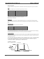
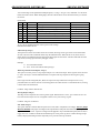
Command Cycle Examples
Index Cycle Resulting From +, -, R Commands
2 8
ADVANCED MICRO SYSTEMS, INC.
SERIAL INTERFACE
Queued Index Cycle Resulting From +, -, R Commands
Constant Velocity Cycle Resulting From M Command
Constant Velocity Cycle From 2nd M Command
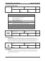
Execution Times
The time for a complete cycle between command entry and result is variable, depending on number of data
bytes, command type, and motion in process. One receipt of the line feed, most commands execute in less
than one millisecond. The exceptions are:
Instruction
I, V (SPS)
C0 (Reset defaults)
C (Clear memory block)
S (Store)
/, ] (Read, Write)
Index +, and R
Execute Time
3-4 ms
60 ms
1500 ms
60 ms
1.1 ms
5-10 ms
Times will vary depending on product. The EASI program has a benchmark feature that can be used to
determine times.
2 9
ADVANCED MICRO SYSTEMS, INC.
3 0
SERIAL INTERFACE
ADVANCED MICRO SYSTEMS, INC.
SMC-27X2 SOFTWARE
Non-Volatile Memory Details
The SMC-27X2 uses the X24C16, a 2048 byte EEPROM. A worst case of 4 bytes per instruction yields a
capacity of 500 commands. These devices are rated to retain data for 100 years. As with all EEPROMS, the
number of times it may be re-programmed is limited. Each time a cell is written a small number of electrons are
trapped in the dielectric. After many write cycles the dielectric becomes less effective and the cell cannot
retain its charge. The write life cycle endurance rating is constantly being improved. At this time a life in
excess of 1 million cycles is available.
To extend the life of the EEPROM in your device it is necessary to be aware of which commands of the
SMC-27X2 perform writes to the EEPROM, and eliminate those which are not needed. For example, the
RESTORE command (“C 0”) will retrieve the parameters from the EEPROM without doing a write. If the
INITIALIZE command (“C 1”) was chosen, the first 256 BYTES of EEPROM are written. If you require a
sequence of motions to be done without host attention, break-up the motions into sub-groups rather than
repeatedly programming the EEPROM. Then use the GO from address command to execute the sub-groups
in the required sequence.
Note: Use the SAVE command sparingly. The SMC-27X2 parameters are set so quickly, even in SERIAL
mode, that you should let the host download them..
Changing parameters should NOT be done by writing directly to EEPROM. The SMC-27X2 won’t recognize
that it was changed and may over-write them. Use the commands available to set parameters. Reading on the
other hand is non-taxing on the EEPROM. The DIVIDE factor is readable at 229 (0E5 hex). Trying to read and
write Initial and Slew velocities from the EEPROM will be confusing as they are stored as timer reload
values. Use the EXAMINE command (“X”) in SERIAL mode.
Memory Map
The following locations are accessible through the NV memory read/write commands:
Decimal
Description
0-127
User program or data storage
128-191
Shadow program area
1601
Trip routine
192-226
Unused
227
Configuration byte
228
Internal initial status byte (Do NOT modify)
229
Divide factor (D)
230-1
Initial velocity low and high bytes (I)
232-3
Pointer value (I)
234-5
Slew speed (V) low and high bytes
236-7
Pointer value (V)
238
Low speed jog value (B)
239
High-speed jog value (B)
240
Acceleration ramp factor (K)
241
Deceleration ramp factor (K)
242-244
Trip Point low, mid and high bytes
245
Port value for trip (“k” data)
246
Resolution
247
Name
248
256-2047
User program or data storage
256-5111
Branch area power up commands
1600-20472
User program power up commands
1
Committed only when specific command is being used, otherwise used as general-purpose storage.
Locations 247 thru 255 are protected from the “Clear” command. Most of the data contained in these
locations is in binary and should not be tinkered with.
2
If a valid command exists at location 1600 through 2047 it will be executed on power up.
3 1
ADVANCED MICRO SYSTEMS, INC.
SMC-27X2 SOFTWARE
Default Table
The following default values are written to NV memory after the ‘Clear’(C 1) command:
Parameter
Initial Velocity (I)
Slew Velocity (V)
Divide Factor (D)
Ramp Slope (K)
Decay threshold (b)
Jog Speeds (B)
Trip Point (T)
Mode (H)
PLC(l)
Limit Polarity (l)
Auto Position Readout (Z)
Name (after reset)
User Programs (0-191)
Value
800 SPS
10,000 SPS
1
5
30
90/600
Off
1/4 micro step
Off (invert all inputs)
Low assert
Off
Unchanged
Cleared
Turbo Ram
The SMC-27X2 has a small, dedicated memory area called Turbo Ram. There are 64 bytes, which reside
between address location 128 and 192. Instructions written here during program mode use “real” internal
RAM rather than EEPROM in order to achieve these advantages:
1. Very fast execution. EEPROM access time is 1 Ms. or more per byte.
2. No wear and tear on the EEPROM.
3. The trip service routine executes at address 160.
Macros may be downloaded directly into this area and executed as frequently as desired. Programs in this
area are stored in corresponding NV memory and “down-loaded” at power up, making an effective shadow
RAM.
Command behavior between address locations128 and 192
Q: List from RAM
P: Program to RAM
S: Copy to EEPROM
]: Write to EEPROM
\: Read from EEPROM
C1: Clear EEPROM, reload register
3 2
ADVANCED MICRO SYSTEMS, INC.
SMC-27X2 SOFTWARE
Command Format Description
Command
Function
Mnemonic
Type
NV Bytes
Data 1
Data 2
(Range)
(Range)
Result
Where:
Command:
Function:
Type:
Keystroke
Functional description of command
Immediate = Direct execution
Program = Executable in stored program
Global = All axis present
Default = Initial parameter setting
Hardware = Auxiliary I/O
NV Bytes:
Storage requirements in program
Mnemonic: Single character prefix used in multi-axis protocol;
(prefixed by axis “name” assignment in party line mode)
Data 1:
Affected parameters
(Range):
Valid numerical range of parameter(s)
Data 2:
Same as Data 1 (as required)
Result:
Information returned as a result of command execution or examination
Note: a comma separates two parameters.
Command
ESC
Function
Type
NV Bytes
Terminate Operation
Immediate
N/A
Mnemonic
Data 1
Data 2
Result
(Name) Esc Char
None
None
Echo #
ESC (Global Abort)
Terminate any active operation and cause the controller to revert to the idle state waiting for a new
command. Output drivers or ports are NOT affected. Stepping and position counter update will cease
immediately without deceleration. The lack of deceleration can cause mechanical overshoot. The controller
will echo a “#” character. This command may not be used within the non-volatile program memory.
Command
@
Function
Type
NV Bytes
Soft Stop
Immediate, Program
1
Mnemonic
Data 1
Data 2
Result
(Name) @
None
None
None
@ (Soft Stop)
If moving, decelerate immediately to a stop using ramp parameters. If running a program, when this
command is entered, the program will terminate after deceleration. The soft stop may be embedded in a
program without causing termination.
3 3
ADVANCED MICRO SYSTEMS, INC.
SMC-27X2 SOFTWARE
An example of this command within a program in conjunction with the Loop on Port command as explained
later is:
P0
M 2000
L0 0
@
P
Command
^C
Enter program mode.
Move at a constant step rate of 2000 SPS.
Loop to memory address location 0 until port 1 is low.
Decelerate and stop program execution.
Exit program mode.
Function
Type
NV Bytes
Reset Controller
None
N/A
Mnemonic
Data 1
Data 2
Result
(Name) ^C
None
None
None
^C (Reset)
Resets controller to power-up condition, waiting for start sequence. It is analogous to “Ctrl-Alt-Delete” reboot the computer. All outputs are set high, defaults are reloaded from NV memory, and position is set to
zero. This command may not be used within the non-volatile program memory. This does not modify the NV
memory values.
Command
A
Function
Type
NV Bytes
Read/Write to Ports
Immediate, Program
2, 2
Mnemonic
Data 1
Data 2
Result
(Name) A (n)
0-129
None
Port Data
A (Port Read/Write)
This command controls the user input/output ports.
Inputs
The A129 command will read a value between 0 and 7 (or 0 and 15 if port 4 is configured as an input). Output
ports are not read.
Ports 1, 2, and 3 (flags 1, 2 and 4) are input ports only. The PLC option flag 8 inverts the sense of these
inputs. Refer to “l” (lower case L) command for option flag information.
Port 4 is configurable as either an input or output, with jumpers.
Port 4 defined as
Input
Output
JP1
2-3
1-2
JP2
1-2
Open
Port 4 as an input:
1. Install JP1and JP2.
2. Insure that P4 input option flag 32 (“l” command) is on.
Outputs
One or two user outputs are available. They will withstand in excess of 30 Vdc and will sink over 1 amp to a
low voltage when turned on. In the off state (after reset and power-up) they have a weak pull up resistor to
VIO.
3 4
ADVANCED MICRO SYSTEMS, INC.
SMC-27X2 SOFTWARE
The PLC option flag 8 has no affect on the output behavior.
Port 4 as an output (as shipped):
1. Install JP1and JP2 in off (storage) position.
2. Insure that P4 input option flag 32 (“l” command) is off.
Port 4 is controlled by the “A 8” (flag 8) command and read back with the A 129 command. The step pulse is
output to P4 when the step/direction out (option flag 2) is set.
Port 5 is an output only. It is turned on with “A 16” command (flag 16). Setting option flag 4 will convert P4
to a moving status output.
Port
1
2
3
Flag
1
2
4
Port
4
5
129
Flag
8
16
Read Port
Reading the port data (A 129) provides the following result information:
Data
1
2
4
8
3
15
Cause (Standard Mode)
Low input present on port 1
Low input present on port 2
Low input present on port 3
Low input present on port 4
Low on ports 1 and 2
Low on ports 1, 2, 3 and 4
Cause (PLC Mode)
High input present on port 1
High input present on port 2
High input present on port 3
High input present on port 4
High on ports 1 and 2
High on ports 1, 2, 3 and 4
Flags are the binary “weight” of the decimal value (0, 1, 2, 4, 8, 16, 32, 64 and 128 for an 8-bit number).
Programming Example
The following example program shows how to turn on an output port. Some uses for this could be
illuminating an LED to signal a sequence is complete, or to operate a valve.
P0
Enter program mode.
A4
Turn on port 3.
W 60
Wait 600milliseconds.
A6
Turn on port 2 and 3.
W 10
Wait 100ms.
A0
Turn off all ports.
P0
Exit program mode.
Note: the actual ports usable for output is determined by the hardware design. AMS products generally
define ports 4 and 5 as outputs.
3 5
ADVANCED MICRO SYSTEMS, INC.
Command
B
SMC-27X2 SOFTWARE
Function
Type
NV Bytes
Set Jog Speeds
Default, Immediate, Program
3
Mnemonic
Data 1
Data 2
Result
(Name) B (n1, n2)
Slow Speed (0-255)
High Speed (0-255)
None
B (Set Jog Speeds)
These two numbers represent the speeds to use for jog inputs. The first is usually a lower speed. The
second number is used when the high-speed jog (pin J1-9) is held low. The values are multiplied by 30 to
determine the actual step rate in FULL steps per second. The controller automatically scales the step rates to
maintain a constant shaft RPM when the microstep resolution is changed.
Setting values of 0 will disable the jog. Speeds are divided by the “D” value. The power-up settings are
stored in NV memory.
This command is generally implemented during the initial customer default parameter assignment. However,
it may be implemented and changed within a program. Following, is an example:
P0
Enters program mode.
B00
Disable jog switches.
+ 100000
Move 100000 in the plus direction.
W0
Wait until move is complete.
B 30 100
Re-enable jog switches.
P
Exit program mode.
Command
b
Function
Type
NV Bytes
Set Slow or Fast Decay
Default, Immediate, Program
2
Mnemonic
Data 1
(Name) b (0, 255)
Speed Threshold
Data 2
Result
None
b (lower case B; Fast and Slow Decay)
The DCB-274 has been designed to add both Slow and Fast decay. When there is no motion (stopped), the
decay will always be slow. The threshold defines a motor speed where slow decay changes to fast decay
during acceleration and switches back to slow decay during deceleration. The threshold will occur at an
RPM where step resolution is taken into account.
Threshold
Value
0
25
50
100
150
200
255
½ SPS
Fast
650
1300
2400
3700
5000
Slow
1/8 SPS
Fast
2400
4800
9600
14000
19200
Because the step rate is actually measured, the decay detection functions for external step pulse input. Slow
decay provides smooth operation with reduced resonance’s at slow to medium speeds. Fast decay will
generally enhance high-speed operation at speeds above 200-300 RPM. The actual settings usually must be
determined empirically (see Addendum: “About Step Motor Current”) and tailored to the specific design.
3 6
ADVANCED MICRO SYSTEMS, INC.
SMC-27X2 SOFTWARE
Multiple variables that interact include:
• Operating step speed range
• Step resolution
• Motor size and characteristics
• Load inertia and load damping affects
• Supply voltage
• Motor current setting
• Acceleration and deceleration rates
Once the optimal settings are determined, they will apply to future production, provided all remains
constant.
Command
C
Function
Type
NV Bytes
Clear and Restore NV Memory
Immediate
N/A
Mnemonic
Data 1
Data 2
Result
(Name) C (n)
0-8
None
Version
C (Clear and Restore NV Memory)
Previously stored programs are erased. Using a 1 forces complete NV memory initialization with factory
default values with erasure of all previously stored programs. This MUST be done when new NV memory is
installed or existing memory is corrupted. Frequent use of this command should be avoided, as memory
longevity may be affected. This command should not be used within the non-volatile program memory. The
“C 0” command simply reads the last stored values into the working registers.
Command
D
Function
Type
NV Bytes
Divide Speeds
Immediate, Program
2
Mnemonic
Data 1
Data 2
Result
(Name) D (n)
Resolution (1-255)
None
None
D (Divide Speeds)
All speeds during ramping and slewing are divided by the specified number (n). The pre-scale number may
range between 1 and 255. Speeds as low as 4 1/2 steps per minute may be obtained. As “n” is increased,
other parameters (internal speeds) must be increased to obtain a given output step speed.
Using a value of 2 is usually necessary to produce smoother acceleration characteristics at Full and Half
step modes. The specified SPS must be doubled to recover the motor shaft speed. D should not be changed
while moving at speeds that require ramping. The power-up settings are stored in NV memory.
This command is generally implemented during the initial customer default parameter assignment. However,
it may be implemented and changed within a program. Following, is an example:
P0
Enter program mode.
D 10
Change the divider to 10.
P
Exit program mode.
Command
Function
Type
NV Bytes
Unused
E
Mnemonic
(Name) E (n)
Unused. See “Y” command.
2
Data 1
Data 2
Result
None
None
3 7
ADVANCED MICRO SYSTEMS, INC.
Command
F
SMC-27X2 SOFTWARE
Function
Type
NV Bytes
Find Home
Immediate, Program
3
Mnemonic
Data 1
Data 2
Result
(Name) F (n, d)
SPS (40-36,000)
Direction (0,1)
None
F (Find Home)
The special Home algorithm is intended to eliminate mechanical hysteresis typically found in many switches,
encoders and is generally present in the form of system mechanical backlash.
The SMC-27X2 microprocessor implements an intelligent homing algorithm whereby home is always
approached from the same direction based on the initial logic state of the Home switch and the value (0 or 1)
assigned to the “d” direction byte.
Normally Open Home Switch
The Find Home step velocity, using a normally open Home switch (actuation from logic high to low) is
programmable over the entire slew velocity available, from 40-36,000 SPS. Once the Home switch is
encountered the system inertia typically overshoots the exact switch transition point so that the controller
changes the direction signal and shifts the step speed down to the (I) initial parameter velocity. This
direction reversal and speed reduction continues until the exact Home switch actuation point is reached and
the Homing function is complete.
Normally Closed Home Switch
The Find Home step velocity, using a normally closed Home switch (actuation from logic low to high) will
always be the (I) initial velocity parameter setting. Once the Home switch is actuated all motion ceases and
the Homing function is complete. The following table illustrates the possible combinations of switch motion:
Home Switch
“d”
Parameter
Direction of Motion
Normally Open (High to Low)
Normally Closed (Low to High)
Normally Open (High to Low)
Normally Closed (Low to High)
0
0
1
1
Negative
Positive
Positive
Negative
This command may be implemented within a program. Following, is an example:
P0
Enter program mode.
F 1000 1 Find the home switch in the “1” direction at a step rate of 1000 SPS.
P
Exit program mode.
Command
G
Function
Type
NV Bytes
Execute Program
Immediate, Program
3
Mnemonic
Data 1
Data 2
Result
(Name) G (a, t)
0-192, 256-2048
Trace (0-1)
None
G (Go)
The Go command is used to execute a user programmed sequence starting at location “a.” Most programs
will start at “0”, however, you may wish to start at another address. The address MUST begin at a stored
instruction address, i.e., “go to” data produces unpredictable results.
3 8
ADVANCED MICRO SYSTEMS, INC.
SMC-27X2 SOFTWARE
If “t” is a one, the TRACE mode is turned on. A display of the current step being executed is produced while
the program is running. The list format is the same as that of the “Q” command The TRACE mode will be in
effect until the program execution terminates or until an embedded ‘Go’ without the trace attribute is
encountered.
The address range is 2047, depending on NV memory capacity. Address locations between 225 and 255 are
reserved for parameter storage and may not be used in programs. The SMC-27X2 also features a special
case for the “Go” instruction.
The controller is factory set with the following program example:
P0
Enter program mode.
+ 1001
Move 1001 steps in the plus direction.
W 100
Wait 100 milliseconds.
- 1000
Move 1000 steps in the minus direction.
W 100
Wait 100 milliseconds.
Z0
Display step position.
G00
Go to location 0 and run stored program.
P
Exit program mode.
Special case “Go”
If the address is specified as 2048 (above the last NV memory address), the SMC-27X2 will read the input
ports, then, branch to an address based on the state of input ports 1 through 4. In such case, each state of
the input ports acts as a “go switch.” To prevent any confusion to the controller, each address should have
a program associated with it even if it is simply “G 2048 0” to go back into the “branch to mode.” The target
address starts at the second page of program memory, starting at address 256 with 16 character (byte)
intervals. This instruction is analogous to “on PORT go to.”
Input Port State:
P1 P2 P3 P4
1
1
1
1
0
1
1
1
1
0
1
1
0
0
1
1
1
1
0
1
0
1
0
1
1
0
0
1
0
0
0
1
1
1
1
0
0
1
1
0
1
0
1
0
0
0
1
0
1
1
0
0
0
1
0
0
1
0
0
0
0
0
0
0
Address of
“Go-to”:
HEX
0
256
1
272
2
288
3
304
4
320
5
336
6
352
7
368
8
384
9
400
A
416
B
432
C
448
D
464
E
480
F
496
The physical input ports are internally inverted as part of the address computation. When the PLC jumper is
in the STD mode (pins 1 and 2) a low is defined as a voltage above ½ VIO (no connect). A high is less than
½ VIO (GND).
When the PLC jumper is in the PLC mode (pins 2 and 3) the inputs are inverted. A low is defined as zero
volts (no connect), a high is a voltage above ½ VIO mode jumper.
Commands located in address space between 129-191 will execute much faster.
3 9
ADVANCED MICRO SYSTEMS, INC.
Command
H
SMC-27X2 SOFTWARE
Function
Type
NV Bytes
Set Step Size Resolution
Default, Immediate, Program
2
Mnemonic
Data 1
Data 2
Result
(Name) H (n)
0-5
None
None
H (Step Resolution)
This command selects step size resolution. The SMC-27X2 has an internal lookup table of up to 32 bytes
corresponding to 1/8 step. This specifies which table is to be used. Each time this command is executed the
values are reset to “step 1” and the armature is repositioned to the start phase. Initial and final velocities
may require appropriate changes.
The H command sets the phase switching sequence:
Steps per rev.
Sequence
H Command (1.8 deg) Motor)
Remark
1/8 Micro
H0
1600
Highest resolution smoothest
1/4 Micro
H1
800
Resonance reduced or higher resolution
Half
H2
400
High torque - 1 phase on/2 phase on
Full
H3
200
Highest torque - 2 phase on
1/2 Micro
H4
400
Low torque - half step
Wave
H5
200
One phase on - full step
This command is generally implemented during the initial customer default parameter assignment. However,
it may be implemented and changed within a program. Following, is an example:
P0
Enter program mode.
H1
Change the resolution to ¼ step.
P
Exit program mode.
Command
I
Function
Type
NV Bytes
Set Initial Velocity
Default, Immediate, Program
3
Mnemonic
Data 1
Data 2
Result
(Name) I (n)
SPS (40-36,000)
None
None
I (Initial Velocity)
This parameter sets the initial velocity in steps per second. This is the first speed used at the beginning of
acceleration. It must be slow enough that the motor can start without loosing steps (stalling).
As with all velocity parameters, the initial velocity is divided by the divide factor (D). Using the examine (X)
command displays updated velocities. The initial velocity applies to:
1. All index commands (+, -, R).
2. First execute in constant velocity.
3. Decelerate to 0 in constant velocity or soft stop.
4. Final phase in home command if home speed is above initial velocity.
See “Default Table” in the beginning of this section.
This command is generally implemented during the initial customer default parameter assignment. However,
it may be implemented and changed within a program. Following, is an example:
P0
Enter program mode.
I 100
Change the initial velocity to 100 SPS.
P
Exit program mode.
4 0
ADVANCED MICRO SYSTEMS, INC.
Command
i
SMC-27X2 SOFTWARE
Function
Type
NV Bytes
Restart Special Trip
Default, Program
5
Mnemonic
(Name) i (n)
Data 1
Next Trip
Position ±8,388,607
Data 2
Result
Port (0-63)*
None
i (lower case I; Restart Special Trip )
See lower case “k” command. *Actual values are determined by the hardware configuration.
Command
J
Function
Type
NV Bytes
Jump to Address
Program
4
Mnemonic
Data 1
Data 2
Result
(Name) J (a, n)
Address (0-2047)
N + 1 Times 0-255
None
J (Jump to Address a, n+1 times)
This loop command allows repetition of a sequence up to 255 times. The address specified MUST be a valid
instruction address, and is usable only within a program. This instruction may NOT be nested, because only
one jump counter is available for use at any given time.
This command may be implemented within a program. Following, is an example:
P0
Enter program mode.
+ 1000
Move in the plus direction 1000 steps.
J03
Go to and run command at location 0, 4 times.
P
Exit program mode.
Command
K
Function
Type
NV Bytes
Set Ramp Slope Time
Default, Immediate, Program
3
Mnemonic
Data 1
Data 2
Result
(Name) K (n1, n2)
Accel (0-255)
Decel (0-255)
None
K (Ramp Slope)
Specify the ramp acceleration and deceleration time. The "K" command is used to adjust the ramp slope
during the motor acceleration or deceleration. An internal lookup table defines the profile or shape of the
acceleration/deceleration curve. Depending on the values of initial and slew velocities, a number of discrete
velocities are used to define the acceleration or deceleration of the motor armature rotation.
The "K" value determines how many steps are made at each step rate point on the acceleration curve during
ramping. Higher "K" values will increase the dwell time at each discrete point on the acceleration ramp.
Lower values of "K" will increase the acceleration rate. A value of 0 will eliminate any ramping.
In practical applications, it is typically easier to decelerate a system, rather than accelerate a system. The
separate decelerate parameter feature is a valuable time saver when compared to systems with fixed
acceleration/deceleration times.
4 1
ADVANCED MICRO SYSTEMS, INC.
SMC-27X2 SOFTWARE
The following two examples are of ramped indexes, each 2000 steps with I=400, V=5000, but different “K”
values; K50 5 and K5 5:
Note: The default value of "K" is 5 (Accel), 5 (Decel). To modify the ramp slope it is always necessary to
enter two (2) data values (from 0 to 255), corresponding to the desired slope for motor acceleration vs.
deceleration. The value of “K” can be proportionally changed if the microstep resolution (H command)
or Divide Speed (D command) is increased.
The K command can be issued:
1. As part of a setup.
2. In an application program.
3. As User defined defaults at reset.
This command is generally implemented during the initial customer default parameter assignment. However,
it may be implemented and changed within a program. Following, is an example:
P0
Enter the program mode.
K 100 50
Change the acceleration ramp to 100 and the deceleration ramp to 50.
P
Exit program mode.
Command
k
Function
Type
NV Bytes
Next Trip Point, Port Output
Default, Program
5
Mnemonic
(Name) k (n)
Data 1
Next Trip
Position ±8,388,607
Data 2
Result
Port (0-63)*
None
k (lower case K; Trip Output Value)
*Actual values are determined by the hardware configuration.
The latency described in use of the “T” command can be avoided via use of the “i” and “k” (both lower
case) commands. Both of these commands implement a trip mode similar to the T command, but there
actions are performed in real time.
The best way to illustrate the power of these commands is with an example:
Enter as follows:
P0
0
O
9
13
16
P 128
4 2
0
+ 6000
W0
P0
Start programming mode.
Set position to zero.
Index 6000 steps.
Force wait till index complete.
End program.
Program RAM commands.
ADVANCED MICRO SYSTEMS, INC.
128
133
138
143
S
G0
k 400 0
k 600 16
i 200 8
P0
SMC-27X2 SOFTWARE
Set new trip at 400 and turn ports off.
Set new trip at 600 and turn port 5 on.
Reset origin, RAM=128, port 4 on.
End program.
Save the shadow RAM program.
Execute program.
Failure to store the program in shadow memory will result in loss of all commands between 128 and 192.
Once they are stored, they will automatically reload with every reset.
The following example further describes the program sequence:
Address
Description
0
“O 0”
The position counter is reset to zero.
4
“k 200 8”
The initialize command “k” is first used to initialize the real time
sequence.
Assume that the command “k 200 8” is executed at the beginning
of the program. The following actions take place:
1. Port 4 is set on per data2 – see the “A” command.
2. The first trip position is set per Data1 (200).
3. A special trip program counter (PC) is set to 128.
9
“+6000”
Now the +6000 index command is started. When the position
matches 200, the command located at 128 is checked for either a
“i” or “k.”
128
“k 200 0”
The “k” changes the trip position to 400 and turns all output ports
off (high logic voltage) This is executed while at the exact 400
position. The program counter is advanced to 133.
133
“k 600 16”
This is executed like the previous 128, new trip=600, ports 4 and
are turned on and the program counter set to 138.
138
“i 200 8”
The restart command performs the same actions as the initial k 200
8 command. Port 4 is turned on, the trip is set to 200 and program
counter is reset to 128.
ONE IMPORTANT ADDITIONAL ACTION is performed. The position counter is reset to ZERO and causes
the repeat of trips 200, 400 and 600.
Notes:
1. The physical motor travel will be 6000 steps, even though the position counter has been reset 10 times.
2. The cycle will repeat 10 times.
3. The position counter ends up at zero.
4 3
ADVANCED MICRO SYSTEMS, INC.
Command
L
SMC-27X2 SOFTWARE
Function
Type
NV Bytes
Loop on Port
Program
3
Mnemonic
Data 1
Data 2
Result
(Name) L (a, c)
0-2048
Condition (0-9)
None
L (Loop on Port)
Loop on Port will test the specified input port for the required condition (c). If the port is NOT at the
required level then the program will jump to the specified address. If the address is to a previous instruction
then the program will loop until it becomes the specified level. The program will then continue to the next
step. The PLC mode inverts the input high/low definitions.
Input ports are available as follows:
Port
Low
High
1
0
1
2
2
3
3
4
5
4
6
7
5
8
9
The SMC-27X2 can view all ports as inputs and outputs, restricted by contention with external hardware.
Any “output” port can be modified, then subsequently used in conjunction with the L, G 2048, or A129
(read) command. The SMC-27X2 has an additional feature of implementing a “wait till” function. The
standard loop tests the condition every 2-3ms. If the unique address is 2048, the controller executes a tight
loop at this instruction, monitoring the specified condition. When the condition is met, program execution
continues.
This feature is helpful in situations where the condition may be of short duration. This command is usable
only in NV memory program execution. Following is an example of this command:
P0
Enter program mode.
L0 4
Stay at location 0 until port 3 is low then go to next command in program.
+ 1000
Move 1000 steps in the plus direction.
P
Exit program mode.
Command
l
Function
Type
NV Bytes
Hardware Options
Default, Immediate, Program
2
Mnemonic
Data 1
(Name) l (a, d)
Option Flags
Data 2
Result
None
l (lower case L; Option Flags)
IMPORTANT – DO NOT CHANGE JUMPERS WITH POWER APPLIED
This command configures several options, primarily relating to input/output operating modes and defining
external hardware. Several options invert the sense of input signals. If appropriate jumpers or input signal
inversion is not matched to the selected option(s) then the system may lock up or motion can be inhibited.
Flags and Numbers
Several commands use “on-off” flags to enable or disable some feature. The data supplied is in decimal
ranging between 0 and 255. The corresponding binary bits are called flags. There are 8 flags, each equaling
binary values of 1, 2, 4, 8, 16, 32, 64, 128.
4 4
ADVANCED MICRO SYSTEMS, INC.
SMC-27X2 SOFTWARE
Two or more flags can be specified for multiple options, i.e., flag 1 + flag 8= 9. So, command “l 9” will invert
limits and set PLC mode. When reading flags, the host software must convert decimal to binary to evaluate
the results.
Option table
Flag Bit
1
0
2
1
4
2
8
3
16
4
32
5
64
6
128
7
Invert limits
Step/dir out
Moving
PLC mode
P4 input
Gentle limit
Reserved
Read back
Function
Both inputs must be held low to allow a move.
Change port 4 and 5 into step and direction out.
Change port 5 into moving signal.
Inverts all input signals.
Inform the controller that port 4 is an input.
Soften limit with decelerate (K).
Note
P4 is output (JP1, JP2)
P4 is output (JP1, JP2)
Set PLC jumper
Based on JP1, JP2
Over shoots limit
Read out the values.
An “S” (save) command must be used to preserve the settings.
Default with CLEAR =all zero.
Limit Polarity (Flag 1)
The input levels on the travel limit sensors are inverted, allowing source type sensors such as hall-effect
devices to be used. This command cannot swap the limit directions. When this bit is set, motor travel in
either direction is inhibited unless the appropriate limit inputs are forced low. The PLC mode will invert the
logic levels (sourcing input necessary to trigger a limit).
Example:
l1
l9
Invert the limit software.
PLC - invert limit software and input logic.
Make Step and Direction Outputs (Flag 2)
This option converts port 4 to a step output and port 5 to a direction output. These signals can be directed
to “slave” driver(s) to control additional motors if required. The step outputs are short negative going
pulses.
Port 4 logic must be configured (JP1, JP2) as an output. The step and direction outputs can be a very
powerful feature as it allows the user to send step pulses and a direction bit to a stand-alone driver, moving
it at the same rate and direction.
Conflicts - Flags 4 and 16 must be off.
Moving Output (Flag 4)
This flag converts output P5 into a moving status signal. While motion is active, port 5 will be at zero volt
level. Several axes may be wire-or’ed together to form an “any axis moving” signal.
Conflicts - Flag 2 is not allowed.
PLC Mode (Flag 8)
This option tells the controller that all inputs are inverted, and to compensate accordingly. The PLC jumper
MUST be installed, This jumper reconfigures the input hardware with pull down rather than pull ups. The
inputs will read zero volts. A positive voltage must be applied to any of the affected inputs (such as GO) to
trigger the “true” condition. If both GO and Soft Stop are true at power up, then a conflict message (single
mode) is displayed and flag 8 will be temporally set to prevent a latch up condition.
4 5
ADVANCED MICRO SYSTEMS, INC.
SMC-27X2 SOFTWARE
Port 4 Input (Flag 16)
This flag informs the controller that Port 4 is to be used as an input. Jumpers JP1 and JP2 must be set
accordingly. The commands; read inputs (A129), branch (G 2048) and loop (L n) will use this input port.
Conflicts - Flag 2 and Flag 4 (outputs) are not permitted.
Example- turn on 3 options:
“l 25” = 1+8+16 = (invert limits) + (PLC mode) + (port 4 = input).
In general, a miss-installed jumper will not cause damage, other than a dysfunction.
Gentle Limit (Flag 32)
Preliminary – not fully tested. When a limit input is activated, the motion (presumably high speed) will
decelerate to zero based on the deceleration value defined by the “K” command. This means that there will
be some travel overshoot. The mechanical design should take this into account.
Command
M
Function
Type
NV Bytes
Move at Constant Velocity
Immediate, Program
3
Mnemonic
Data 1
Data 2
Result
(Name) M
SPS (±40-36,000)
None
None
M (Move at a Constant Velocity)
The “+” or “-” sign determines direction during the move at constant velocity function. The motor will ramp
up, or down to a constant velocity. Motion will continue at the given speed until a new velocity is entered.
The specified slew speed is in steps per second. Ramp parameters may be modified prior to each velocity
command, allowing different ramp slopes. The direction is specified by the sign preceding the velocity. The
SMC-27X2 has the capability of decelerating from full speed in one direction, then accelerating to full speed
in the opposite direction with this single command.
Motion may be terminated by:
1. The “M 0” command
2. Soft stop command or interrupt
3. Abort (ESC) interrupt (without deceleration)
The default initial velocity is used at the first invocation of the command. The following commands modify
effective speeds and resolutions:
4. Divide
5. Ramp factor
6. Step Resolution
An example of this command within a program, in conjunction with the Loop on Port and Soft Stop
commands, is as follows:
P0
Enter program mode.
M 2000
Move at a constant step rate of 2000 SPS.
L0 0
Loop to memory address location 0 until port 1 is low.
@
Decelerate and stop program execution.
P
Exit program mode.
4 6
ADVANCED MICRO SYSTEMS, INC.
Command
O
SMC-27X2 SOFTWARE
Function
Type
NV Bytes
Set Origin
Immediate, Program
4
Mnemonic
Data 1
Data 2
Result
(Name) O
Position (±8,388,607)
None
None
O (Set Origin)
This command sets the internal 24-bit position counter to the specified value. Zero position for the
RELATIVE mode is “0000.” Signed numbers are used. Hardware reset clears to “0000.” The position counter
is incremented or decremented for all motion commands. During any index the position counter is used only
for trip value comparison. This counter may be changed without affecting the distance of travel in process.
This command may be implemented within a program. It is very useful when used in conjunction with the
Find Home and Relative Positioning commands. Following, is an example:
P0
Enter program mode.
F 1000 1 Find the Home switch in the “1” direction at a step rate of 1000 SPS.
O
Set origin and counter to 0.
R 1000
Move to position 1000 relative to 0.
P
Exit program mode.
Command
P
Function
Type
NV Bytes
Program Mode On/Off
Immediate
N/A
Mnemonic
Data 1
Data 2
Result
(Name) P (a)
Address (0-2047)
None
None, #
P (Program Mode)
The P command is always used in pairs. The first “P” initiates the program mode at the specified address.
Once in this mode all commands and data are directed into the NV memory for future execution. Entering the
second “P” command will terminate the PROGRAM mode, and then insert an end of program marker (0FFh)
in the stored program. The controller will then return to the COMMAND mode.
The program mode may also be terminated with the ESCape character, causing immediate return to the
COMMAND mode without inserting the end of program marker. This is useful for editing sections of the
program, without requiring that all commands be re-entered.
More than one program may exist at different addresses. These commands can than be executed via the “G
(address)” command. There are special address ranges that are assigned to various functions:
Address
128-191
256-511
1600
Function
Fast “shadow” RAM
“G 2048” command
Power-up routines
4 7
ADVANCED MICRO SYSTEMS, INC.
Command
Q
SMC-27X2 SOFTWARE
Function
Type
NV Bytes
List Program
Immediate
N/A
Mnemonic
Data 1
Data 2
Result
(Name) Q (a)
Address (0-2047)
None
Listing
Q (List Program) (Note: Use in dumb terminal, single line mode).
List program stored in non-volatile memory using the format:
Address
Instruction
Value 1
Value 2
The values will be displayed only if applicable to the particular instruction type. Twenty instructions are
displayed at a time. Use the <CR> key to list up to 20 more commands without pause. ESC quits and any
other key single steps the listing.
Command
R
Function
Type
NV Bytes
Index Relative to Origin
Immediate, Program
4
Mnemonic
Data 1
Data 2
Result
(Name) R (n)
Position (±8,388,607)
None
None
R (Index Relative to Origin)
Move, with ramping, relative to the “0” origin. The target position has a range of ±8,388,607 steps from the
‘0’ origin.
The motion sequence is:
1. Wait until any previous motion is finished,
2. Read the current position then calculate the distance to the new target position,
3. Energize the motor winding,
4. Start stepping at the rate of the initial velocity (I),
5. Accelerate using a profile defined by the fixed table that approximates straight-line acceleration and a
slope set by the “K” command,
6. The acceleration continues until the slew speed as specified by the “V” command is attained,
7. Motion continues at the slew speed, until the deceleration point is reached,
8. Decelerate (determined by the second “K” value) to a stop completing the index,
9. If another index is not commanded for the settling period, power down the motor (if auto power down
is enabled).
This command may be implemented within a program. It is very useful when used in conjunction with the
Origin command. Following, is an example:
P0
Enter program mode.
O
Set origin and counter to 0.
R 1000
Move to position 1000 relative to 0.
P
Exit program mode.
4 8
ADVANCED MICRO SYSTEMS, INC.
Command
S
SMC-27X2 SOFTWARE
Function
Type
NV Bytes
Save Parameters to NV Memory
Immediate
1
Mnemonic
Data 1
Data 2
Result
(Name) S
None
None
None
S (Save)
The following parameters are saved in the NV memory and will be recalled as defaults during power-on reset:
1. NV memory addresses 128 through 191 (shadow RAM)
2. Initial velocity (I)
3. Slew velocity (V)
4. Divide factor (D)
5. Ramp slope (K)
6. Jog speeds (B)
7. Resolution mode (H)
8. Auto power down (E)
9. Limit polarity (l)
10. Name (for party line use)
11. Trip point settings
All of these parameters are saved as a block from the working registers in the SMC-27X2. Frequent use of
this command should be avoided, as memory longevity may be affected.
Command
T
Function
Type
NV Bytes
Set and Enable Trip Point
Default, Program
4
Mnemonic
Data 1
Data 2
Result
(Name) T (n)
Position (±8,388,607)
Address (0-255)
None
T (Trip Point)
During motion operations, the position counter is continuously updated. If the trip point function is
enabled, the position is continuously compared to the programmed trip position. When equality is detected,
a trip event will be triggered. If a program is running, a call or "Go Sub" will be made to the specified address
between 1 and 255.
Programs located at the specified address can perform almost any function, including turning on/off ports
and setting new trip points. A trip point cannot be "reentered" i.e., when executing a trip subroutine and a
new trip is set as part of the routine, the new trip cannot be triggered until the end of the first trip routine.
Routines located between 128 and 192 will execute faster because of the "Shadow RAM" feature. Trip
service routines should not contain index, wait or time consuming instructions.
Disable
To turn off the trip function, use 0 (zero) as the address parameter. The trip is not currently usable in the
encoder mode. The following is an example (all commands are followed by a <CR>):
1. Write program to location 0 (zero).
P0
Enter program mode at address 0.
0
A8
Turn port 4 on.
2
+2000 Rotate motor 2000 steps in the plus direction.
6
P0
Exit program mode.
4 9
ADVANCED MICRO SYSTEMS, INC.
2. Write program to location 100.
P100
100
A129
102
A0
104
P0
SMC-27X2 SOFTWARE
Enter program mode at address 100.
Read port states.
Turn port 4 off.
Exit program mode.
3. Set Trip Point.
In “dumb terminal” mode enter T1000 100. This tells the controller to run the program located at
address 100 when the step position is 1000.
4. Run program.
Enter the “G” command. Port 4 will turn on and the motor will start moving. When the motor
position is at 1000, the program will vector to address 100 and run that sequence. The number 8,
signifying port 4, will appear on the screen.
Command
V
Function
Type
NV Bytes
Set Final (Slew) Velocity in SPS
Default, Immediate, Program
3
Mnemonic
Data 1
Data 2
Result
(Name) V (n)
SPS (40- >36,000)
None
None
V (Set Slew Speed)
This is the maximum speed to be used after acceleration from the initial velocity. The maximum speed will be
limited by the motor capability and/or power driver circuitry.
The final output velocity is divided by the value of “D.” This value is independent of constant velocity (M),
jog (B) or home (F) speeds and is used when indexing absolute or relative (+, -, R commands).
If full or half step mode is chosen, the acceleration time may become to fast for larger motors. This is due to
the high speed SMC27X2 microprocessor. A “D 2” pre-scale divider may be required to provide smoother
acceleration characteristics.
Example
Assume that the desired running speed is 12,000 full steps per second (3600 RPM). The speed (“V”) can be
set to 24,000 SPS with D = 2.
Thus:
SPS (motor) = V/D or 24000/2 =12,000 SPS
With the “D 2” divider, the full output speed range is approximately 20 to 20,000 SPS.
See “Default Table.”
This command is generally implemented during the initial customer default parameter assignment. However,
it may be implemented and changed within a program. Following is an example:
P0
Enter program mode.
V 10000 Change the slew velocity to 10000 SPS.
P
Exit program mode.
5 0
ADVANCED MICRO SYSTEMS, INC.
Command
W
SMC-27X2 SOFTWARE
Function
Type
NV Bytes
Wait (n) Milliseconds
Immediate, Program
3
Mnemonic
Data 1
Data 2
Result
(Name) W (n)
10 ms. (0-65,535)
None
None
W (Wait)
The controller will remain in an idle state for the specified time. The Wait command, if issued while indexing
(as a result of an R, +, -, or F command), timing will NOT start until the motion has completed.
Wait until motion complete
Using this command with zero time can provide an alternate method of determining motion. If issued while
running at constant velocity, the time-out will occur without waiting for motion to cease. High-speed step
operation during Wait commands will increase the delay time by as much as 14 times the normal value. The
result will NOT be available until the delay is complete.
The following example program makes a move, waits for motion to complete, then turns on an output port.
Some uses for this could be illuminating a LED, signaling a sequence is complete or operating a valve.
P0
Enter program mode.
+ 1000
Move 1000 steps in the plus direction.
W0
Wait for move to finish.
A8
Turn on port 4.
W 500
Wait 50milliseconds.
A0
Turn off port.
P0
Exit program mode.
Command
w
Function
Type
NV Bytes
Wait (n) Milliseconds
Immediate, Program
3
Mnemonic
Data 1
Data 2
Result
(Name) w (n)
10 ms. (0-255)
None
None
w (lower case W; Pre-energize)
The “w” command is a “pre-energize” command that can insure that motor current has built up when a step
command is executed while in the “holding current” state. This parameter is useful under certain conditions,
and should be zero (off) if possible. The following conditions might require “pre-energize” time:
1. Automatic current setback (“E” command) is in effect.
2. If the delay between consecutive motion commands exceeds 1 second.
3. If the initial speed (“I” command) specified is too high.
4. If the acceleration requirements are excessive.
When the auto current setback is used, motor current will be reduced after approximately one second of idle
time. When a new motion command (+, -, R, M, F, etc) is executed the windings are re-energized almost
instantly with the first motor step. Thus the motor must rapidly change from a “relaxed” position to the next
step.
This pre-energize insures a delay after turn on. The delay is not used if the setback timeout (from a prior
motion) is not timed-out. That is, the motor current is still at 100%. The drawback is that this function can
introduce a substantial start delay.
5 1
ADVANCED MICRO SYSTEMS, INC.
SMC-27X2 SOFTWARE
The controller will remain in an idle state for the specified time. The Wait command, if issued while indexing
(as a result of an R, +, -, or F command), timing will NOT start until the motion has completed.
NV default =0
The following example program pre-energizes the controller to the run current then makes a move.
P0
Enter program mode.
w 25
Pre-energize the controller for 250 milliseconds.
+ 1000
Move 1000 steps in the plus direction.
P0
Exit program mode.
Command
X
Function
Type
NV Bytes
Examine Settings
Immediate
N/A
Mnemonic
Data 1
Data 2
X
None
None
Result
Display
Setting
X (Examine)
The Examine command produces two different responses, depending on the mode of operation. When NOT
in the multi-axis mo de (non-daisy chain or party line) the display is as follows:
X K= 5/5, I= 400, V= 5016, D= 1, ½, n=C
Where:
K= Ramp up/ramp down
I= Initial velocity
V= Slew velocity
D= Divide factor
½= Resolution mode
n= Axis name
In the multi-axis (daisy chain or party line) mode the data is returned in the following format:
mm[LF]
mm= model (26)
Command
Y
Function
Type
NV Bytes
Program Hold and Run Current
Default, Immediate, Program
3
Mnemonic
Data 1
Data 2
(Name) Y
Hold 0-100
Run 0-100
Result
(Y) Hold and Run Current
This command allows specifying the Hold and Run values of motor current (per phase) between 0 and 100%
with a resolution of 1%. The value 100% represents a maximum of 4 amps per phase. The switching between
Hold and Run values is automatic whenever a motion function is executed. Current reduction to the "Hold"
value is automatic and occurs when stationary. A settling time (nominally 1 second) is inserted after each
move is completed.
The maximum current is limited to a value that will not consume more than the 100VA and is available from
your power supply.
5 2
ADVANCED MICRO SYSTEMS, INC.
SMC-27X2 SOFTWARE
The following procedure is used to access the independently programmable "Hold" and "Run" current
feature:
1. Issue the "Y" command to program the desired current values. Entering Y10 80 yields a 10% Hold
current and 80% Run current.
2. Issue an "S" (Save) command. The values are now stored in non-volatile memory.
On receipt of an index or other motion command, the control circuits are incremented to the 80% boost, while
moving is in process. On completion of motion (and settling time delay) the current is automatically reduced
to the 10% Hold current level.
Quiet Mode
To access the "Current Disable" feature use the following current setup procedure:
Enter
Y00 80
Result
Initiates current program mode, sets Hold current at 0% and Run current at 80% of
maximum. The 4-amp drive would be set for 3.2 amps peak.
Note: Refer to “About Step Motor Current” in the Addendum for more detail on setting the proper motor
current.
Command
Z
Function
Type
NV Bytes
Read and Display Current Position
Immediate
1
Mnemonic
Data 1
Data 2
Result
(Name) Z
Readout Mode (0-1)
None
Position
Z (Read Position)
During motor move commands the value will change depending on the direction of travel. The counter is
programmable by the “O” command.
The SMC-27X2 has the option of continuous readout via the serial interface. The “Z 1” command enables
this operation. Any change in position causes the position data to be sent to the serial output. The readout
is terminated by a carriage return only.
The readout mode will be defaulted as “On” if a SAVE command is issued. This mode is only practical using
single axis protocol.
The controller is factory set with the following program example:
P0
Enter program mode.
+ 1001
Move 1001 steps in the plus direction.
W 100
Wait 100 milliseconds.
- 1000
Move 1000 steps in the minus direction.
W 100
Wait 100 milliseconds.
Z0
Display step position.
G00
Go to location 0 and run stored program.
P
Exit program mode.
5 3
ADVANCED MICRO SYSTEMS, INC.
Command
[
SMC-27X2 SOFTWARE
Function
Type
NV Bytes
Read NV Memory
Immediate
N/A
Mnemonic
Data 1
Data 2
(Name) [
Address (0-2047)
Sequential Bytes (0-255)
Result
Displayed
Values
[(Read NV Memory)
The user may display any byte of the 2047 byte external NV memory. The address specifies the desired
location to access. At addresses 128-191 the NV memory is always Read (not the RAM). The data contained
at the specified location is output as a decimal value.
This command is normally used external from the controller’s non-volatile program. Example:
[ 0 20
Command
]
The result from this command would be 20 sequential bytes starting at location 0 and
finishing at location 19.
Function
Type
NV Bytes
Read Limits, Hardware
Immediate, Program
2
Mnemonic
Data 1
Data 2
Result
(Name) ]
0-1
None
Status
] (Read Limits, Hardware)
This command allows the user to examine the status of the various switch inputs. The result will contain the
state of the limit switch inputs and current phase outputs in binary values as follows:
Decimal value:
Bit position:
SMC-27X2:
Where:
La =
Lb =
Hm=
P 0-5=
128
7
Lb
64
6
La
32
5
Hm
16
4
P5
8
3
P4
4
2
P3
2
1
P2
1
0
P1
Limit “a” switch
Limit “b” switch
Home switch (32 = low input)
Ports 1-5 (see “A” command)
“] 1” Read other inputs:
This command reads other inputs; some of which can be used by external applications under the condition
that the SMC-27X2 does not use them. For instance, if the jog speeds are set to zero, the three jog inputs
could be used as general-purpose inputs.
Decimal value:
Bit position:
SMC-27X2:
128
7
JOG-S
64
6
JOG2
32
5
JOG1
16
4
*
8
3
*
4
2
*
2
1
*
1
0
*
The returned number is converted to an 8-bit byte, each bit represents the state of the specified data.
This command is normally used external from the controller’s non-volatile program. Example:
]0
5 4
The result from this command would be in decimal format indicating what I/O port is
active.
ADVANCED MICRO SYSTEMS, INC.
Command
+
SMC-27X2 SOFTWARE
Function
Type
NV Bytes
Index in Plus Direction
Immediate, Program
4
Mnemonic
Data 1
Data 2
Result
(Name) + (n)
Steps (0-16,777,215)
None
None
+ (Index in Plus Direction)
Step in the positive direction for the specified step count.
The motor will ramp up, slew, and then ramp down per the previously set parameters. The range is 0 to
16,777,215. The position counter will overflow at 8,388,607.
The motion sequence is:
1. Wait until any previous motion is finished,
2. Energize the motor winding as required,
3. Start stepping at the rate of the initial velocity (I),
4. Accelerate using a profile defined by the fixed table that approximates straight-line acceleration and a
slope set by the “K” command,
5. Accelerate until the slew speed, as specified by the “V” command, is attained,
6. Motion continues at the slew speed, until the deceleration point is reached,
7. Decelerate (determined by the second “K” value) to a stop completing the index,
8. If another index is not commanded for the settling period, power down the motor (if auto power down
is enabled).
The DCB-274 is factory set with the following program example:
P0
Enter program mode.
+ 1001
Move 1001 steps in the plus direction.
W 100
Wait 100 milliseconds.
- 1000
Move 1000 steps in the minus direction.
W 100
Wait 100 milliseconds.
Z0
Display step position.
G00
Go to location 0 and run stored program.
P
Exit program mode.
Command
-
Function
Type
NV Bytes
Index in Minus Direction
Immediate, Program
4
Mnemonic
Data 1
Data 2
Result
(Name) – (n)
Steps (0-16,777,215)
None
None
- (Index in Minus Direction)
Same as “+” command only in the opposite direction.
5 5
ADVANCED MICRO SYSTEMS, INC.
Command
^
SMC-27X2 SOFTWARE
Function
Type
NV Bytes
Read Moving Status
Immediate, Program
1
Mnemonic
Data 1
Data 2
Result
(Name) ^
None
None
Status
^ (Read Moving Status)
The host may use this command to determine the current moving status that exists within the SMC-27X2. A
non-zero value indicates moving.
This command is normally used external from the controller’s non-volatile program. The command would
look like:
^
Command
\
The result from this command would be a decimal number. Any number other than 0 indicates
the controller is moving.
Function
Type
NV Bytes
Write to NV Memory
Immediate
N/A
Mnemonic
Data 1
Data 2
Result
(Name) \ (a, d)
Address (0-2047)
Data (0-255)
None
\ (Write to NV Memory)
This command allows the programmer to modify any location in the memory. The command being changed
must be done so in decimal format. Special step sequences may be entered, and all initialization constants
may be changed. (Reference “Memory Map” in the beginning of this section for specific locations).
The life expectancy of the NV memory may be affected by this command. This command complements the
Read NV Memory ( [ ) command. Addresses 128-191 in the NV memory are always written to (not the RAM).
This is a very powerful command and care must be taken not to overwrite other needed sections of the
nonvolatile program. The example of this command is as follows:
AMS controllers are factory set with the following program example:
P0
Enter program mode.
+ 1001
Move 1001 steps in the plus direction.
W 100
Wait 100 milliseconds.
- 1000
Move 1000 steps in the minus direction.
W 100
Wait 100 milliseconds.
Z0
Display step position.
G00
Go to location 0 and run stored program.
P
Exit program mode.
Let’s say you wish to change the G 0 0 section of the program to the soft stop command @. When you
query the program it shows the G command at location 16. The decimal value for the @ command is 0. So, to
change the G 0 0 command to a soft stop you would enter the following command line:
\ 16 0
5 6
ADVANCED MICRO SYSTEMS, INC.
Command
SMC-27X2 SOFTWARE
Function
Type
NV Bytes
Terminate Program
Immediate
2
Mnemonic
Data 1
Data 2
(Name)
Result
Status
Byte
| (Selective Termination)
This command (pipend: vertical dash key-Shift \) can be placed at a point to terminate (equivalent to
ABORT) the program that was started via the "G" command or hardware GO input. The Terminate command
may be used to individually "ABORT" a single axis in multiple axis systems, when the global "ESC"
command is not appropriate.
Program Example
P0
0O
1I
4T
9M
12 I
15 V
18 G
21 P
400
1000 128
5000
1000
1000
18
0
P 128
Trip Routine Start
Decelerate and Index
Wait
Show Position
Abort Program (where “axis name” is the selected axis to
terminate)
End Program Flag
Save Code at 128
128
+2000
133 W
0
136 Z
138 (axis name)
140 P
Set Origin To Zero
Initial SPS
Set a Trip
Start Motion
Change Initial SPS
Slew
Wait
End Program Flag
0
S
Issue "GO": The sequence will complete and show the position that the number of extra steps is due to
(decelerate) ramp plus a few steps of overhead. The overstep difference is repeatable.
Command
^N
Function
Type
NV Bytes
Name Controller
None
N/A
Mnemonic
Data 1
Data 2
Result
^N
None
None
None
^N (Name Axis)
Response to the single character “Ctrl N“ (14 decimal, 0E hex) is immediate.
This command must be executed with one axis attached, otherwise a bus conflict will occur and all axes may
receive the same name. On entry of the “Ctrl N” the controller responds with “name?” Type the desired
name, the character will be stored in NV memory and the DCB-274 is ready to enter party line mode.
5 7
ADVANCED MICRO SYSTEMS, INC.
Command
^P
SMC-27X2 SOFTWARE
Function
Type
NV Bytes
Restart in Party Line Mode
None
N/A
Mnemonic
Data 1
Data 2
Result
^P
None
None
None
^P (Party Line Mode)
Response to the single character “Ctrl P” (16 decimal, 10 hex) is immediate.
This control character restarts the controller in party line mode. One, or up to 32 controllers may be
connected. The “^C” (or cycle power) command is used to restart in single controller (space to sign-on)
mode.
AMS - SIN-11 Serial Adapter
If you are using a SIN-11 serial adapter from AMS, the “&” command must be used to initiate party line
operation. On receipt of the “&” command, the SIN-11 automatically transmits the ^P character within the
party line startup routine. See the serial communication section for more information.
5 8
ADVANCED MICRO SYSTEMS, INC.
ADDENDUM
Command Summary
MNEMONIC / COMMAND
DATA 1
RANGE 1
+
ESC
@
^C
[
\
]
^
^N
^P
|
A
B
b
C
D
E
F
G
H
I
i
J
K
k
L
l
M
O
P
Q
R
S
T
U
V
W
w
X
Y
Z
INDEX IN "+" DIRECTION
INDEX IN "-" DIRECTION
ABORT/TERMINATE
SOFT STOP
SOFTWARE RESET
READ NV MEMORY
WRITE TO NV MEMORY
READ LIMITS/HARDWARE
READ MOVING STATUS
NAME CONTROLLER
ENTER PARTY LINE MODE
SELECTIVE TERMINATE
PORT R/W
SET JOG SPEEDS
FAST AND SLOW DECAY
CLEAR AND RESTORE
DIVIDE STEP RATE
STEPS
STEPS
1- 16,777,215
1- 16,777,215
FIND HOME
GO
RESOLUTION MODE
INITIAL VELOCITY
RESTART SPECIAL TRIP
JUMP
RAMP SLOPE
TRIP OUTPUT VALUE
LOOP ON PORT
INVERT LIMIT/STEP -DIR
MOVE AT CONST. VEL.
SET ORIGIN
PROGRAM MODE
QUERY PROGRAM
INDEX TO POSITION
STORE PARAMETERS
TRIP POINT
RESERVED
SLEW VELOCITY
WAIT, (DELAY)
PRE ENERGIZE
EXAMINE PARAMETERS
RUN AND HOLD CURRENT
DISPLAY POSITION
DATA 2
RANGE 2
NV
D
4
4
2
ADDRESS
ADDRESS
LIM/HW
0-2047*
0-2047*
0-1
BINARY
SLOW
PAGE
DIVIDER
0-128
0-255
0-255
0-9
0-255
SPS
ADDRESS
TABLE#
SPS
NEXT TRIP
ADDRESS
ACCEL
NEXT TRIP
ADDRESS
OPTIONS
SPS
STEPS
ADDRESS
ADDRESS
POSITION
40-36000
0-2048*
0-5
40-36000
±8388607
0-2048*
0-255
±8388607
0-2048*
0-255
±36000
±8388607
0-2047*
0-2047*
±8388607
DIRECTION
TRACE
POSITION
±8388607
VECTOR
SPS
0.01 SEC
0.01 sec
40-36000
0-65535
0-255
HOLD
CONTINUE
0-100
0-1
DECAY MODE
NUMBER
DATA
HIGH
PORT
N+1 TIMES
DECEL
PORT
CONDITION
0-255
0-255
0-255
0-1
0-1
0-63
0-255
0-255
0-63
0-8
2
2
3
2
¤
¤
2
¤
3
3
2
3
5
4
3
5
4
2
3
4
¤
¤
¤
RUN
0-100
¤
¤
¤
¤
¤
¤
¤
¤
¤
¤
¤
¤
¤
¤
¤
¤
¤
¤
¤
¤
¤
¤
¤
¤
¤
¤
¤
4
0-255
I
¤
¤
¤
¤
4
?
3
3
2
¤
3
¤
¤
P
¤
¤
¤
¤
¤
¤
¤
¤
¤
¤
¤
¤
¤
¤
¤
¤
¤
¤
¤
¤
¤
¤
¤
?
¤
¤
¤
¤
¤
¤
¤
¤
¤
* Program address ranges are 0-192, 256-2047, 2048 is used as a special case, 128 – 192 is high speed “shadow”
RAM.
5 9
ADVANCED MICRO SYSTEMS, INC.
ADDENDUM
ASCII Character Code
Ctrl
Char
^@
6 0
Dec
Hex
Code
Dec
Hex
00
00
NUL
32
20
Char
Dec
Hex
Char
Dec
Hex
Char
64
40
@
96
60
`
^A
?
01
01
SOH
33
21
!
65
41
A
97
61
a
^B
?
02
02
STX
34
22
“
66
42
B
98
62
b
^C
?
03
03
ETX
35
23
#
67
43
C
99
63
c
^D
?
04
04
EOT
36
24
$
68
44
D
100
64
d
^E
?
05
05
ENQ
37
25
%
69
45
E
101
65
e
^F
?
06
06
ACK
38
26
&
70
46
F
102
66
f
^G
•
07
07
BEL
39
27
‘
71
47
G
103
67
g
^H
?
08
08
BS
40
28
(
72
48
H
104
68
h
^I
?
09
09
HT
41
29
)
73
49
I
105
69
i
^J
?
10
0A
LF
42
2A
*
74
4A
J
106
6A
j
^K
?
11
0B
VT
43
2B
+
75
4B
K
107
6B
k
^L
?
12
0C
FF
44
2C
,
76
4C
L
108
6C
l
^M
?
13
0D
CR
45
2D
-
77
4D
M
109
6D
m
^N
?
14
0E
SO
46
2E
.
78
4E
N
110
6E
n
^O
¤
15
0F
SI
47
2F
/
79
4F
O
111
6F
o
^P
?
16
10
DLE
48
30
0
80
50
P
112
70
p
^Q
?
17
11
DC1
49
31
1
81
51
Q
113
71
q
^R
?
18
12
DC2
50
32
2
82
52
R
114
72
r
^S
?
19
13
DC3
51
33
3
83
53
S
115
73
s
^T
¶
20
14
EC4
52
34
4
84
54
T
116
74
t
^U
§
21
15
NAK
53
35
5
85
55
U
117
75
u
^V
?
22
16
SYN
54
36
6
86
56
V
118
76
v
^W
?
23
17
ETB
55
37
7
87
57
W
119
77
w
^X
?
24
18
CAN
56
38
8
88
58
X
120
78
x
^Y
?
25
19
EM
57
39
9
89
59
Y
121
79
y
^Z
?
26
1A
SUB
58
3A
:
90
5A
Z
122
7A
z
^[
?
27
1B
ESC
59
3B
;
91
5B
[
123
7B
{
^\
?
28
1C
FS
60
3C
<
92
5C
\
124
7C
|
^]
?
29
1D
GS
61
3D
=
93
5D
]
125
7D
}
^^
?
30
1E
RS
62
3E
>
94
5E
^
126
7E
~
^_
?
31
1F
US
63
3F
?
95
5F
_
127
7F
ADVANCED MICRO SYSTEMS, INC.
ADDENDUM
About Step Motor Current
There is much confusion regarding the operation of step motors. Depending on your application, the step
motor offers several advantages over servo motor designs, including lower cost and simplicity. The step (or
stepper, or stepping) motor is a digital “synchronous” motor with a pre-designed number of “steps” per
revolution. The most common motor has 200 full steps per revolution. Simple driver electronics can
subdivide these steps into ½ step or more complex “microsteps.”
Step Motor Characteristics
• The positional repeatability of each full or half step is very close to exact.
• While microsteps are repeatable, they tend to be somewhat non-linear.
• The torque is maximum at zero speed.
• The motor shaft RPM exactly correlates with the steps-per-second.
• Torque decreases with speed, eventually to zero or a “stall” condition.
• Resonance at certain speeds can cause undesired stalls or erratic operation.
There is little difference between today’s step motor and the first generation of 60+ years ago. The magnetic
materials and torque have been improved, yet it remains a simple, reliable workhorse of industrial motion
control. Over time most improvements have been made to the drive and control electronics, i.e., microstep,
solid-state components with higher voltage, current and switching speeds.
One insatiable hunger of a step motor is torque output at higher speeds. Winding inductance is the villain
that limits speed. As the windings are switched on, the magnetic flux must be built up from current flow in
the windings, producing mechanical torque. Higher step rates reduce the time available for flux to buildup
and average current flow is reduced.
AM23_210_3 4A RMS MOTOR
200
180
160
140
160V
oz-i n
120
100
80
80V
60
40
20
0
10
40V
100
1000
10000
half steps / sec
100000
Note: The DCB-274 is rated for 40 volts only.
This reduced current results in reduced torque. The rate of current change depends on the voltage applied
across it. High voltage applied across the coil will shorten the time constant.
Today’s systems strive for low inductance motors and high voltage supplies. The above curves show the
increased speed that might be obtained with higher supply voltages, up to 160Vdc. At standstill the average
motor voltage is regulated to approximately 3Vdc.
6 1
ADVANCED MICRO SYSTEMS, INC.
ADDENDUM
A current sense circuit is used to switch off the current when it reaches the set value; hence the motor
power is regulated. These “chopper“ circuits operate at speeds above 20khz, well above hearing limits.
The following is an abstract from “Control of Stepping Motors, a Tutorial” (linked from
www.stepcontrol.com) by Douglas W. Jones, University of Iowa Department of Computer Science.
http://www.cs.uiowa.edu/~jones/step/index.html.
“Small stepping motors, such as those used for head positioning on floppy disk drives, are usually driven at
a low DC voltage, and the current through the motor windings is usually limited by the internal resistance of
the winding. High torque motors, on the other hand, are frequently built with very low resistance windings;
when driven by any reasonable supply voltage, these motors typically require external current limiting
circuitry.”
“There is good reason to run a stepping motor at a supply voltage above that needed to push the maximum
rated current through the motor windings. Running a motor at higher voltages leads to a faster rise in the
current through the windings when they are turned on, and this, in turn, leads to a higher cutoff speed for
the motor and higher torques at speeds above the cutoff.”
“Microstepping, where the control system positions the motor rotor between half steps, also requires
external current limiting circuitry. For example, to position the rotor 1/4 of the way from one step to another,
it might be necessary to run one motor winding at full current while the other is run at approximately 1/3 of
that current.”
Motor Choice
The discussion here relates to bipolar chopper motors. Internally, standard motors have 4 windings,
resulting in a total of 8 wire leads. Motor manufacturers supply various configurations:
Leads
8
6
Application Connection
Bipolar (series or parallel),
unipolar
Unipolar or bipolar series
4
Bipolar series or bipolar parallel
5
Unipolar only
Comment
All 8 leads are available. External interconnect can be
cumbersome and untidy.
Can be used with 50% copper reduced torque but increased
speed possible.
Series: higher torque but reduced speed capability.
Parallel: higher speed with lowered torque.
Not suitable for bipolar drives. See AMS model CCB-25 with
programmable phase sequencing.
Determining the Current Value
Question: What is the right current value?
Answer: The minimum value to operate reliably.
As the step motor current is reduced below the rated current, the torque output is reduced and eventually
the motor will stall. The ideal current setting minimizes heating of motor and electronics, increases reliability,
and reduces power supply requirements. Motors run more quietly and resonance effects can be reduced.
One drawback from low current operation is that some microstep size linearity may be reduced, but full or
half step accuracy is not adversely affected.
6 2
ADVANCED MICRO SYSTEMS, INC.
ADDENDUM
AMPS and Wire Count and Power
The rated current is specified based on the rated power input (watts) of a given motor.
A. Basic 8 Wire Motor
While never actually used as 8 individual coils, virtually all permanent magnet motors have 4 internal coils.
All common configurations can be constructed from the 8-wire motor.
Let us assume that each of 4 windings of the 8-wire motor has the
following specifications:
Current = 1 amps
Resistance =2.0 ohm (each of 4 coils)
Voltage= 2.0 volts
Inductance = 4.4 mH
1
5
2
6
The power per winding is:
I2R or 2 x 2 x 1= 4 watts,
x 4 coils = 16 watts total for this motor.
3
7
4
8
A Basic 8 Wire Motor
These values correspond closely with a NEMA size 23, 4 wire motor designs.
These following examples will configure the basic 8-wire motor into four real life connections:
1B
1
5
2
6
7
4
2A
3
8
2B
1A
4 Wire Parallel
The high-speed model implements parallel coil connection. Two coils
connected in parallel result in the following for each of the two phases:
Parallel Resistance= 1 ohms
Parallel Inductance= 2.2 mH
Current= 2.83 amps (8 watts/phase)
Watts per phase=8 (x 2 phases) = 16 watts total
4 Wire Parallel
1B
1
5
2
1A
6
Note that the series inductance is FOUR times the parallel design.
Inductance limits the obtainable speed, since the time constant limits
the amount of flux (hence torque) when step-to-step time is short.
7
4
2A
3
8
2B
B. 4 Wire Series
Changing to a series design, we have two pairs of two coils
connected in series. Each has:
Series Resistance= 4 ohms
Inductance= 17.5 mH
The rated current is now 1 amps (4 Volts)
Watts per phase=8 (x 2 phases) = 16 watts total
4 Wire Series
6 3
ADVANCED MICRO SYSTEMS, INC.
ADDENDUM
C: Adapting Available 6 Wire Motors
A 6-wire motor is equivalent to the 4-wire series motor.
1B
In practice the two coil ends are connected, while no connection is made
to the center tap.
2B
2A
1A
6 Wire Motor
Half Copper or 50% Winding
The maximum speed can be increased by using ½ the coil. To do this,
connect the driver between the center tap and one end of the winding.
PIN 1
PIN 2
PIN 5
Often a 6-wire design is being upgraded or the size, features, availability
or cost dictate the 6-wire motor. Some characteristics can make the motor
impossible to use. Many motors are rated at voltages in excess of 5 volts.
This means that 10 volts is necessary in the series (100% copper)
configuration.
PIN 4
The tradeoff is a loss of torque. The RMS current is the manufacturer’s
unipolar amperage rating with the same wattage per phase.
6 Wire, Half Copper
Aside from having excessive inductance, proper chopper operation dictates operation from voltage sources
much higher than the motor rating. The minimum recommended value for VMM (DC supply) is 2 times the
winding rating (the higher the better, until excessive heating occurs or insulation breakdown).
The Empirical Method for Fine Tuning Your System
The “empirical” method is the best approach for “fine-tuning” the system and can/should be used for all
AMS products. When the best values are determined they can be used in future production, providing
tolerances are sufficiently close.
In this sequence index commands must be executed at the actual “worst case” operating speeds and
conditions.
1. Gradually reduce the current until operation becomes erratic or undesirable.
2. Increase the current gradually until reliable operation is obtained. Then increase the current
equally by 10 to 20%.
In any of these adjustments, monitor motor temperature and insure that excessive heating does not occur.
Larger motors require more time for temperature to stabilize. When a low hold current and short run cycle is
used, heating effects are reduced.
*Optimum amperage is the lowest current where the application indexing is reliable. Sometimes higher
currents (still below the motor ratings) will decrease reliability.
6 4
ADVANCED MICRO SYSTEMS, INC.
ADDENDUM
Application Notes
V1.10 Double Speed Characteristics
The X2 speed (Version 1.10) introduces several new characteristics:
1. Step rates in excess of 36K steps per second.
2. Faster command execution.
3. Intelligent current decay control.
4. Redirect ports 4 and 5 to Step and Direction outputs (mode command).
5. Redirect port 4 as a moving output (mode command).
Note that the minimum step rate is now 40 SPS. Slower step rates are obtained using the “D” (divide)
command.
The I, V, and M commands now have a range of 40 to 36,000 SPS. Values entered below 40 SPS will be
limited to approximately 40 SPS, Values above 36,000 SPS are accepted, and the SPS will increase to a 42,000
SPS ceiling and the acceleration ramp will become non-contiguous. As with all models, the top speed is
reduced when trip points are introduced.
The best resolution is generally ¼ step (default). It provides smoother operation, with diminished
resonances, and is a good match with the acceleration ramp.
Full and Half Step Recommendations
The acceleration ramp profile is slightly modified (over previous designs) to accommodate the increased
dynamic range. Consequently, the number of acceleration points that would be used with full and half
stepping are reduced from previous low speed versions. This may manifest itself in a tendency to stall
during ramp -up. Using the command “D2” (divide all rates by 2) may provide a smoother acceleration –
deceleration. To obtain an equal shaft RPM, your specified speeds must be doubled, i.e., “V 5000” becomes
“V 10000.” Other D values can be used, as long as the V (SPS) value is in range. This technique produces a
longer ramp slope thus allowing the “K” command values to be reduced.
FAQ
Q. When I set the SPS values, the X command reads back a different value?
A. The SMC27X2 controller uses integer values for determining the “time per step”.
Decay Control
Fast decay mode regulates motor current by varying the duty cycle and applying full negative DC bus
voltage to the motor windings when OFF. Applying full DC bus voltage in this manner causes the motor
winding current to change at a rapid rate; hence ‘fast decay.” The fast decay mode of operation permits
better current regulation, but increases motor heating due to the higher current transients.
Slow decay mode also regulates motor current by varying the duty cycle, but instead, shorts the motor
windings when OFF (i.e. zero volts vs. maximum DC bus voltage). The slow decay mode of operation permits
higher currents (higher torque) at lower speeds with less motor heating; but also exhibits poor low current
regulation.
6 5
ADVANCED MICRO SYSTEMS, INC.
ADDENDUM
Serial Adapter Summary
AMS offers several serial adapters. These are used to connect a standard computer RS-232 “D” connector
to the serial I/O on AMS controllers (axis).
Four, model SIN-“n” adapters are currently available, as follows.
SIN-7, SIN-9 (not recommended for multi-axis applications)
These are the lowest cost adapters. They are passive (without electronics) and are suitable for use with only
one axis at any given time. Most new products employ a RS-422 interface. While RS-422 specifications differ
from RS-232, these adapters will generally work over short cable runs.
For more than one axis, party line operation is not supported with these adapters. However, the original
AMS “daisy chain” protocol can be used.
The SIN-7 has a standard 25 pin serial connect.
The SIN-9 has a standard 9 pin serial connect.
SIN-8
This adapter contains the proper RS-232 to RS-422 electronics, powered from the AMS controller. It is
reliable over long distances, and supports party line operation for 1 to 32 controllers. A mechanical switch is
used to place the controllers into either single or party line mode.
Disadvantages: A host computer must have proper software that performs the rigorous handshake protocol.
The software development can be expensive or impossible to implement in some operating systems.
SIN-10 (recommended for new designs)
The SIN-10 contains a microcomputer that performs all the handshake protocol and much more. Even a
single axis design will benefit from the software development timesavings.
6 6