1
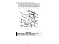
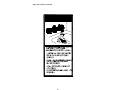
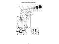
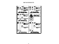
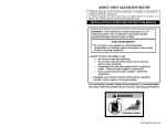
DIRECT VENT GAS WATER HEATER
A Spanish language version of these instructions is available by contacting the
company listed on the rating plate.
La versión espãnola de estas instrucciones se puede obtener al escribirle a la
fábrica cuyo nombre aparece en la placa de especificaciones.
INSTALLATION & OPERATING
INSTRUCTION MANUAL
WARNING: If the information in these instructions is
not followed exactly, a fire or explosion may result
causing property damage, personal injury or death.
FOR YOUR SAFETY
Do not store or use gasoline or other flammable,
combustible, or corrosive vapors and liquids in the
vicinity of this or any other appliance.
WHAT TO DO IF YOU SMELL GAS
• Do not try to light any appliance.
• Do not touch any electrical switch; do not use any
phone in your building.
• Immediately call your gas supplier from a neighbor’s
phone. Follow the gas supplier's instructions.
• If you cannot reach your gas supplier, call the fire
department.
Installation and service must be performed by a qualified
installer, service agency or the gas supplier.
For your family’s comfort, safety and convenience, it is
recommended this water heater be installed and serviced by a
plumbing professional.
238-45839-00D REV 07/07
CONGRATULATIONS!
You have just purchased one of the finest water heaters
on the market today!
This installation, operation and instruction manual will
explain in detail the installation and maintenance of your
new Direct Vent Gas Water Heater. We strongly
recommend that you contact a plumbing professional for
the installation of this water heater.
We require that you carefully read this manual, as well as
the enclosed warranty, and refer to it when questions
arise. If you have any specific questions concerning
your warranty, please consult the plumbing professional
from whom your water heater was purchased. For your
records we recommend that you write the model, serial
number and installation date of your water heater in the
maintenance section in the back of this manual.
This manual should be kept with the water heater.
We’re committed to providing you with the finest water
heater made.
2
TABLE OF CONTENTS
page
GENERAL INFORMATION ........................................................... 4
INSTALLATION ........................................................................... 5
Locating The Water Heater .......................................................... 5
Minimum Clearances.................................................................... 8
Optional Direct Vent-Air Intake Terminal Guard ........................ 9
Venting ..........................................................................................11
Horizontal and Vertical Vent-Air Intake Lengths .......................13
Vent-Air Intake System Installation.............................................16
Water Connections .......................................................................24
Gas Connections ..........................................................................28
GENERAL OPERATION......................................................... 29
Lighting and Shutdown Instructions ..........................................30
Thermostat Adjustment ...............................................................31
Burner Flame Checks...................................................................32
MAINTENANCE ..............................................................................33
PARTS LIST ....................................................................................36
PARTS LIST DRAWINGS
Direct Vent Water Heater..............................................................37
Vent-Air Intake Kits ......................................................................38
INSTALLATIONS FOR POTABLE WATER AND SPACE
HEATING ................................................................................ 39
NOTES .................................................................................... 40
3
GENERAL INFORMATION
This gas-fired water heater’s design is certified by CSA International under
the American National Standard Z21.10.1 - (as indicated on the rating plate)
and CSA 4.1-M - (as indicated on the rating plate).
This water heater must be installed in accordance with local codes or, in the
absence of local codes, the National Fuel Gas Code, ANSI Z223.1-Latest
Edition) and/or in Canada CAN/CGA B149 Installation Codes (Latest
Editions). The warranty for this water heater is in effect only when the water
heater is installed, adjusted, and operated in accordance with these
Installation and Operating Instructions. The manufacturer will not be held
liable for any damage resulting from alteration and/or failure to comply with
these instructions.
This water heater is not design certified for installation in a mobile home.
Such an installation may create a hazardous condition and will nullify the
warranty.
This water heater has been designed and certified for the purpose of heating
potable water. The installation and use of this water heater for any purpose
other than the heating of potable water may cause damage to the water
heater and create a hazardous condition and nullify the warranty.
CAUTION
Incorrect operation of this appliance may create a hazard to life and
property and will nullify the warranty.
Do not use this appliance if any part has been submerged in water. You
should contact a qualified service technician to inspect the appliance and to
replace any part of the control system including the combination gas control,
which has been submerged in water.
DANGER
Do not store or use gasoline or other flammable, combustible, or
corrosive vapors and liquids in the vicinity of this or any other
appliance.
4
General Information continued-
IMPORTANT
Before proceeding, please inspect the water heater and its components for
possible damage. DO NOT install any damaged components. If damage
is evident then please contact the supplier where the water heater was
purchased or the manufacturer listed on the rating plate for replacement
parts.
Make sure that you check the rating plate and combination gas control on
the water heater to be certain that the type of gas being supplied
corresponds with the marking on the rating plate and combination gas
control.
A sacrificial anode is used to extend tank life. The removal of this anode, for
any reason, will nullify the warranty. In areas where water is unusually active,
an odor may occur at the hot water faucet due to a reaction between the
sacrificial anode and the impurities in the water. If this should happen, an
alternative anode may be purchased from the supplier that installed this
water heater. This will minimize the odor while protecting the tank.
Additionally, the water heater should be flushed with appropriate dissolvers
to eliminate any bacteria.
INSTALLATION
LOCATING THE WATER HEATER
WARNING
Water heaters are heat producing appliances. To avoid damage or injury,
do not store materials against the water heater or vent-air intake system.
Use proper care to avoid unnecessary contact (especially by children) with
the water heater and vent-air intake components. UNDER NO
CIRCUMSTANCES SHALL FLAMMABLE MATERIALS, SUCH AS
GASOLINE OR PAINT THINNER BE USED OR STORED IN THE
VICINITY OF THIS WATER HEATER, VENT-AIR INTAKE SYSTEM OR IN
ANY LOCATION FROM WHICH FUMES COULD REACH THE WATER
HEATER OR VENT-AIR INTAKE SYSTEM.
This water heater MUST NOT be installed in any location where
gasoline or flammable vapors are likely to be present, unless the
installation is such to eliminate the probable ignition of gasoline or
flammable vapors.
5
Installation (Locating The Water Heater) continued-
Water heaters in residential garages must be installed and located, or
protected, to avoid physical damage. For other installations refer to
local codes. In the absence of local codes, the water heater must be
installed in compliance with the National Fuel Gas Code, (ANSI Z223.1Latest Edition), or in Canada CAN/CGA B149.1 Natural Gas Installation
Code (Latest Edition) or CAN/CGA B149.2 Propane Installation Code
(Latest Edition).
The location of this water heater is of the utmost importance. Before
installing this water heater read the Installation section of these instructions.
After reading these Installation and Operating Instructions, select a location
for the water heater where the floor is level and is easily accessible to gas
and water supply lines. DO NOT locate the water heater where water
lines could be subjected to freezing temperatures. Make sure the cold
water pipes are not located directly above the gas control so that
condensate during humid weather does not drip on the controls.
This water heater MUST be installed indoors out of the wind and
weather.
To comply with NSF requirements this water heater is to be:
a) Sealed to the floor with sealant, in a smooth and easily cleanable
way, or
b) Installed with an optional leg kit that includes legs and/or extensions
that provide a minimum clearance of 6” beneath the water heater.
Note: For California installation this water heater must be braced,
anchored, or strapped to avoid falling or moving during an earthquake.
See instructions for correct installation procedures. Instructions may
be obtained from California Office of the State Architect, 400 P Street,
Sacramento, CA 95814.
Water heater corrosion and component failure can be caused by the heating
and breakdown of airborne chemical vapors. Examples of some typical
compounds that are potentially corrosive are: spray can propellants, cleaning
solvents, refrigerator and air conditioning refrigerants, swimming pool
chemicals, calcium and sodium chloride, waxes and process chemicals.
These materials are corrosive at very low concentration levels with little or no
odor to reveal their presence. NOTE: DAMAGE TO THE WATER HEATER
CAUSED BY EXPOSURE TO CORROSIVE VAPORS IS NOT COVERED
BY THE WARRANTY. DO NOT OPERATE THE WATER HEATER IF
EXPOSURE HAS OR WILL OCCUR. DO NOT STORE ANY
POTENTIALLY CORROSIVE COMPOUNDS IN THE VICINITY OF THE
WATER HEATER.
6
Installation (Locating The Water Heater) continued-
WARNING
Liquefied petroleum gases/propane gas are heavier than air and will
remain at floor level if there is a leak. Basements, crawl spaces,
closets and areas below ground level will serve as pockets for
accumulation of leaking gas. Before lighting, smell all around the
appliance area for gas. Be sure to smell next to the floor.
IF YOU SMELL GAS:
• Do not try to light any appliance.
• Do not touch any electric switch; do not use any telephone in
your building.
• Immediately call your gas supplier from a neighbor’s
telephone. Follow the gas supplier’s instructions.
• If you cannot reach your gas supplier, call the fire department.
DO NOT OPERATE APPLIANCE UNTIL THE LEAKAGE IS
CORRECTED!
WARNING
DO NOT ATTEMPT TO LIGHT ANY GAS APPLIANCE IF YOU ARE
NOT CERTAIN OF THE FOLLOWING:
•
•
•
•
•
Liquefied petroleum gases/propane gas and natural gas have an
odorant added by the gas supplier that aids in the detection of
the gas.
Most people recognize this odor as a “sulfur” or “rotten egg”
smell.
Other conditions, such as “odorant fade” can cause the odorant
to diminish in intensity, or ”fade”, and not be as readily
detectable.
If you have a diminished sense of smell, or are in any way unsure
of the presence of gas, immediately contact your gas supplier
from a neighbor’s telephone.
Gas detectors are available. Contact your gas supplier, or
plumbing professional, for more information.
7
Installation (Locating The Water Heater) continued-
The water heater must be located close enough to the outside wall to keep
the venting distance within the maximum distance described in the
installation instructions. Note: The direct vent-air intake terminal must be
installed on a vertical wall. Read the venting section in this installation
instruction manual before locating the water heater.
This water heater must be located in an area where leakage of the tank or
water line connections and the combination temperature and pressure relief
valve will not result in damage to the area adjacent to the water heater or to
lower floors of the structure. When such locations cannot be avoided, a
suitable drain pan, adequately drained, must be installed under the water
heater. The pan must not restrict combustion airflow. The drain pan must
have a minimum length and width of at least 4 in. (10.2 cm) greater than the
diameter of the water heater and must not restrict proper combustion air flow
to the water heater. The drain pan, as described above, can be purchased
from your plumbing professional. The drain pan must be piped to an
adequate drain. The piping must be at least 3/4 inch (1.9 cm) in diameter
and pitched for proper drainage.
It is recommended that a minimum clearance of four (4) inches (10.2 cm) be
provided on the side of the water heater for servicing and maintenance of the
combination temperature and pressure relief valve.
MINIMUM CLEARANCES
WARNING
Failure to adhere to these installation and operating instructions
may create a hazard to life and property and will nullify the
warranty.
This installation shall allow access to the front of the water heater and
adequate clearance shall be provided for servicing and operating this
water heater. The water heater may be installed on either a combustible or
non-combustible floor. If the water heater is to be installed directly on
carpeting, it shall be installed on top of a metal or wood panel extending
beyond the full width and depth of the appliance by at least three (3) inches
(76.2 mm) in any direction or, if the appliance is to be installed in an alcove
or closet, the entire floor shall be covered by the panel. The minimum
clearances to combustibles for this water heater is: zero (0) inch (0 cm) from
the sides and rear, four (4) inches (10.2 cm) from the front of the jacket, zero
(0) inch (0 cm) from the plenum, zero (0) inch (0 cm) from the air intake
elbow and telescopic tubes and twelve (12) inches (30.5 cm) from the direct
vent-air intake terminal. (See Figure 1).
8
OPTIONAL DIRECT VENT-AIR INTAKE TERMINAL GUARD
WARNING
The direct vent-air intake terminal is HOT while the water heater is
in operation. Do not touch. Keep children, combustibles, gasoline
and other liquids having flammable vapors away.
It is recommended that a vent-air intake terminal guard be installed when the
vent-air intake terminal is located where it can be touched accidentally, or
accessed by children. (See Figure 2).
A chain link or louvered fence may be used instead of the vent-air intake
terminal guard. Maintain proper clearances as specified in this instruction
manual to the vent-air intake terminal. (See Figure 3).
Figure 1
9
Installation continued-
Figure 2
Figure 3
10
VENTING
This is a Direct Vent Gas Water Heater where all air for combustion is
obtained from the outside atmosphere and all flue gases are discharged to
the outside atmosphere.
WARNING
The vent-air intake system must be properly installed. Failure to
properly install the vent-air intake system properly could result in
property damage, personal injury or death.
DO NOT install any damaged vent-air intake system components.
Contact the manufacturer of the water heater for replacement parts.
Figure 4
Direct Vent Terminal Clearances
A=
E=
Clearance above grade, veranda,
porch, deck or balcony
Clearance to widow or door that may
be opened
Clearance to permanently closed
widow
Vertical clearance to ventilated soffit
located above the terminal within a
horizontal distance of 2 feet (61 cm)
from the center line of the terminal
Clearance to unventilated soffit
F=
Clearance to outside corner
B=
C=
D=
G=
Clearance to inside corner
H=
Clearance to each side of center line
extended above meter/regulator
assembly
Canadian
Installations1
US Installations2
12 inches (30
cm)
12 inches (30
cm)
*b
12 inches
(30 cm)
9 inches (23 cm)
12 inches (30
cm) *a
12 inches (30
cm) *a
12 inches (30
cm) *a
*b
12 inches (30
cm) *a
*b
*b
*b
3 feet (91 cm)
within a height
15 feet (4.6 m)
above the
meter/regulator
assembly
*b
11
*b
Venting continued-
I=
J=
K=
L=
M=
Canadian
Installations1
US Installations2
Clearance to service regulator vent
outlet or oil tank vent
Clearance to non-mechanical air
supply inlet to building or the
combustion air inlet to any other
appliance
Clearance to a mechanical air supply
inlet
36 inches
(91 cm)
12 inches
(30 cm)
*b
Clearance above paved sidewalk or
paved driveway located on public
property
Clearance under a veranda, porch,
deck, or balcony
7 feet
(2.13 m)†
6 feet
(1.83 m)
12 inches (30
cm) ‡
9 inches
(23 cm)
3 feet (91 cm) above if
within 10 feet
horizontally
*b
*b
1
In accordance with the current CAN/CGA-B149 Installation Codes.
In accordance with the current ANSI Z223.1-(Latest edition)/NFPA 54 National Fuel Gas Code.
† A vent shall not terminate directly above a sidewalk or paved driveway that is located between two
single-family dwellings and serves both dwellings.
‡ Permitted only if a veranda, porch, deck or balcony is fully open on a minimum of two sides beneath
the floor.
*a) A minimum clearance value determined by testing in accordance with section 2.20.
*b) “Clearance in accordance with local installation codes and the requirements of the gas supplier”.
2
The vent system must terminate so that proper clearances are maintained as
cited in local codes or the latest edition of the National Fuel Gas Code, ANSI
Z223.1.73.4e and 7.8a, b as follows:
1. Do not terminate near soffit vents or crawl space or other area
where condensate or vapor could create a nuisance or hazard or
cause property damage.
2. Do not terminate the exhaust vent terminal where condensate or
vapor could cause damage or could be detrimental to the operation
of regulators, relief valves, or other equipment.
3. Do not terminate the exhaust vent terminal over public area or
walkways where condensate or vapor can cause nuisance or
hazard.
4. The vent shall terminate a minimum of 12 inches above expected
snowfall level to prevent blockage of vent termination.
Vent pipes serving power vented appliances are classified by building codes
as “vent connectors”. Required clearances from combustible materials must
be provided in accordance with information in this manual under LOCATION
OF WATER HEATER and CLEARANCES, and with National Fuel Gas Code
and local code
12
Venting continued-
The co-axial vent-air intake tubes of this water heater can be installed in any
360° configuration as long as the proper clearances for installation,
plumbing, operation and servicing are maintained. (See Figure 5).
Figure 5
Note: Maintain proper clearances for installation, plumbing, operation
and service.
HORIZONTAL AND VERTICAL VENT-AIR INTAKE LENGTHS
This Direct Vent Gas Water Heater comes one (1) vent-air intake “Kit C”.
Optional vent-air intake kits are available that can extend the horizontal
length and/or vertical height of the vent-air intake system. Table A lists the
various vertical and horizontal vent-air intake system configurations.
13
Installation (Horizontal and Vertical Vent-Air Intake Lengths) continued-
The water heater is shipped with the following standard vent and air intake
system: 239-41097-00. The components of this vent and air intake systems
is as follows:
3” Vent Tube*
5” Air Intake Tube*
Vent Terminal
Inner Wall Term. Mounting Flange
Outer Wall Term. Mounting Flange
Vent Terminal Hardware
RTV Silicone Sealant
3” Vent Elbow
5” Vent Elbow
*The vent and air intake telescopes from 13 3/4" to 23 11/16”.
Table A
13 1/4
14 3/16
Vertical "Y"
10
14 3/4
15 11/16
16 1/2
19 3/16
23 3/4
33 11/16
37 1/2
57 3/8
59 13/16
105 13/16
order
kit A
*order
kit A (2)
order
kit A & B
order
kit A
order
kit A & C
order
kit D & A
Horizontal "X"
15
22 1/4
36
17 11/16 32 3/16
55 7/8
58 5/16
104 5/16
order
order
no add'l
order
kit B
kit D
kit req'd
kit C
order
order
order
order
kit A & B
kit A
kit A & C kit A & D
*order
order
order
order
kit B (2)
kit B
kit B & C kit B & D
order
order
*order
order
kit B
kit C
kit C (2)
kit D
order
*order
*order
order
kit C & B kit C (2) kit C (3) kit C & D
order
*order
order
order
kit D & B
kit D
kit D & C kit D (2)
* (2) = Order two of the kits referenced.
* (3) = Order three of the kits referenced.
The bold text above show what kit(s) are needed in addition to the standard
vent and air intake tubes. If the standard vent and air intake tubes are not
used in the venting system (those that do not have bold text) they can be
discarded or saved.
14
Installation (Horizontal and Vertical Vent-Air Intake Lengths) continued-
Figure 6
15
VENT-AIR INTAKE SYSTEM INSTALLATION
WARNING
The vent-air intake system must be properly installed. Failure to
properly install the vent-air intake system could result in property
damage, personal injury or death.
Do not install any damaged vent-air intake system components.
Contact the manufacturer of the water heater for replacement parts.
IMPORTANT
When the following instructions specify, to seal a vent-air intake joint,
use only Loctite Ultra Blue 587 RTV Silicone sealant. A tube of Loctite
Ultra Blue 587 RTV Silicone sealant is supplied with every direct vent
water heater and each optional vent-air intake kit. Make sure that all
joints are completely sealed.
When drilling pilot holes for the #8 sheet metal screws through the
five (5) inch (12.7 cm) diameter components, be careful not to drill into
the inner three (3) inch (7.6 cm) diameter components.
Tools Required For Vent-Air Intake Installation
The following minimum tools are required to properly install the ventair intake system. Note: Wall construction will determine tool usage.
•
•
•
•
•
•
•
•
•
•
Tape Measure
Drill
3/16 inch Diameter Drill Bit(s)
1/8 inch Diameter Drill Bit(s)
Masonry Drill Bit(s) (For Poured Concrete, Concrete Block and
Brick Wall Construction)
Reciprocating Saw w/appropriate Blade(s) (Dependent on Wall
Construction)
Chisel
(For Poured Concrete, Concrete Block and Brick Wall
Construction)
Hammer (For Poured Concrete, Concrete Block and Brick Wall
Construction)
1/4 & 5/16 inch Nut Drivers (Preferred) or Slotted Head
Screwdriver
Phillips Head Screwdriver
16
Installation (Vent-Air Intake System Installation) continued-
1. Measure the vertical height “Y” required in your installation. (See Figure
6). Reference the appropriate Table A to determine number of vent-air
intake kits required in your installation.
2. Measure the horizontal length “X” required in your installation (See
Figure 6). Reference Table A to determine number of vent-air intake kits
required in your installation.
3. Cut a 5-1/2 inch (14 cm) diameter minimum clearance hole in the wall at
the point where the vent-air intake tubes will pass through the outside
wall and connect with the direct vent-air intake terminal
(See Figure 6).
4. From outside the building, position the outer wall mount plate and direct
vent-air intake terminal over the center of the opening. Mark the
mounting screw hole locations. With a 3/16 inch diameter drill bit (not
supplied), drill holes for the wall anchors (supplied). Install the wall
anchors but DO NOT affix the outer wall mount plate and direct vent-air
intake terminal to the wall at this time (See Figure 7). Note: Certain
construction of walls may require the use of a different type of wall
anchoring means than supplied. DO NOT modify the direct vent-air
intake terminal or outer wall mount plate.
Figure 7
17
Installation (Vent-Air Intake System Installation) continued-
IMPORTANT
The following instructions detail the installation of the standard
horizontal vent-air intake kit supplied with the water heater.
5. Insert the straight end of the three (3) inch (7.6 cm) diameter elbow into
the flue reducer until firmly seated and oriented in the correct direction.
With a 1/8 inch diameter drill bit (not supplied), drill three (3) holes, 120o
apart, through the flue reducer into the three (3) inch (7.6 cm) diameter
elbow. Fasten with three (3) #8 sheet metal screws (supplied). Using
the supplied special RTV silicone sealant, apply a sufficient amount to
seal the joint (See Figure 8).
Figure 8
6. Place the straight end of the five (5) inch (12.7 cm) diameter elbow over
the three (3) inch (7.6 cm) diameter elbow and plenum collar until seated
on top of the plenum box. Make certain that the five (5) inch (12.7 cm)
diameter elbow is oriented in the same direction as the three (3) inch
(7.6 cm) diameter elbow and both are oriented in the correct direction.
Drill three (3) 1/8 inch diameter holes, 120o apart, through the five (5)
inch (12.7 cm) diameter elbow into the plenum collar. Fasten with three
(3) #8 sheet metal screws (supplied) (See Figure 9).
18
Installation (Vent-Air Intake System Installation) continued-
Figure 9
7. Extend the three (3) inch (7.6 cm) diameter telescopic tube to its
maximum length and slide the backing plate over it. Place the large end
of the three (3) inch (7.6 cm) diameter telescopic tube through the hole
in the outside wall. Insert the smaller end of the three (3) inch diameter
(7.6 cm) telescopic tube into the flared end of the three (3) inch (7.6 cm)
diameter elbow, one (1) inch (2.5 cm) (or until seated). Drill three (3) 1/8
inch diameter holes, 120o apart, through the three (3) inch (7.6 cm)
diameter elbow into the three (3) inch (7.6 cm) diameter telescopic tube.
Fasten with three (3) #8 sheet metal screws (supplied). Adjust the
overall length of the three (3) inch (7.6 cm) diameter telescopic tube so
that 2-1/2 inches (6.4 cm) extends beyond the outside wall. Drill three (3)
1/8 inch diameter holes, 120o apart, through the three (3) inch (7.6 cm)
diameter telescopic tubes where the small and large sections overlap.
Fasten with three (3) #8 sheet metal screws (supplied). Using the
supplied special RTV silicone sealant, apply a sufficient amount to seal
the joints (See Figure 10).
19
Installation (Vent-Air Intake System Installation) continued-
Figure 10
8. Extend the five (5) inch (12.7 cm) diameter telescopic tube to its
maximum length. Place the large end of the five (5) inch (12.7 cm)
diameter telescopic tube over the collar on the outer wall mount plate.
Drill three (3) 1/8 inch diameter holes, 120o apart, through the five (5)
inch (12.7 cm) diameter telescopic tube into the collar on the outer wall
mount plate. Fasten with three (3) #8 sheet metal screws (supplied).
Using the supplied special RTV silicone sealant, apply a sufficient
amount to seal the joint (See Figure 11).
Figure 11
20
Installation (Vent-Air Intake System Installation) continued-
9. From outside the building, slide the five (5) inch (12.7 cm) diameter
telescopic tube through the opening in the wall until the outer wall mount
plate is flush with the wall (See Figure 12).
Figure 12
10. Using the supplied special RTV silicone sealant, apply a bead one (1)
inch (2.5 cm) from the end of the three (3) inch (7.6 cm) diameter tube
that is part of the vent-air intake terminal. Slide the direct vent-air
intake terminal into the three (3) inch (7.6 cm) diameter telescopic tube
that extends through the wall and position it so it is flush with the outer
wall mount plate. Make sure that the rain guard and the word “HOT” on
the end of the direct vent-air intake terminal are oriented properly.
Secure the direct vent-air intake terminal to the outer wall mount plate
and wall with four (4) #10 x 1 inch screws (supplied) (See Figure 13).
Note: Certain construction of walls may require the use of different type
of anchoring means than supplied. DO NOT modify the direct vent-air
intake terminal or outer wall mount plate.
21
Installation (Vent-Air Intake System Installation) continued-
Figure 13
11. From inside the building, slide the backing plate over the five (5) inch
(12.7 cm) diameter telescopic tube until it is flush with the wall. Adjust
the length of the five (5) inch (12.7 cm) diameter telescopic tube and
insert the end into the flared end of the five (5) inch (12.7 cm) diameter
elbow one (1) inch (2.5 cm) (or until seated). Drill three (3) 1/8 inch
diameter holes, 120o apart, through the five (5) inch (12.7 cm) diameter
elbow into the five (5) inch (12.7 cm) diameter telescopic tube and
through the tubes where the small and large sections overlap. Fasten
with three (3) #8 sheet metal screws (supplied). Using the supplied
special RTV silicone sealant, apply a sufficient amount to seal all joints
(See Figure 14).
Figure 14
22
Installation (Vent-Air Intake System Installation) continued-
12. Mark the mounting screw hole locations for the backing plate. Rotate
the backing plate in order to gain access to the markings. With a 3/16
inch diameter drill bit (not supplied), drill holes for the supplied wall
anchors. Install the wall anchors and secure the backing plate to the
wall with four (4) #10 x 1 inch screws (supplied) (See Figure 15). Note:
Certain construction of walls may require the use of a different type of
anchoring means than supplied.
Figure 15
IMPORTANT
When the installation is complete, visually inspect the air intake
system to insure that all joints are completely sealed.
23
WATER CONNECTIONS
Note: BEFORE PROCEEDING WITH THE INSTALLATION, CLOSE THE
MAIN WATER SUPPLY VALVE.
After shutting off the main water supply, open a faucet to relieve the water
line pressure to prevent any water from leaking out of the pipes while making
the water connections to the water heater. After the pressure has been
relieved, close the faucet. The COLD water inlet and HOT water outlet are
identified on the top of the water heater. The fittings at the cold water inlet
and hot water outlet are dielectric waterway fittings with 3/4” NPT male
thread. Make the proper plumbing connections between the water heater
and the plumbing system to the house. Install a shut-off valve in the cold
water supply line.
CAUTION
If sweat fittings are to be used, DO NOT apply heat to the nipples on top
of the water heater. Sweat the tubing to the adapter before fitting the
adapter to the water connections. It is imperative that heat is not applied
to the nipples containing a plastic liner.
24
Water Connections continued-
WARNING
For protection against excessive temperatures and pressure, install
temperature and pressure protective equipment required by local codes,
but not less than a combination temperature and pressure relief valve
certified by a nationally recognized testing laboratory that maintains
periodic inspection of production of listed equipment or materials as
meeting the requirements of the Standard for Relief Valves and
Automatic Gas Shutoff Devices for Hot Water Supply Systems, ANSI
Z21.22 and the Standard CAN1-4.4 Temperature, Pressure,
Temperature and Pressure Relief Valves and Vacuum Relief Valves.
The combination temperature and pressure relief valve must be marked
with a maximum set pressure not to exceed the maximum working
pressure of the water heater. The hourly BTU discharge capacity or the
rated steam relief capacity of the combination temperature and pressure
relief valve must not be less than the input rating of the water heater.
Install the combination temperature and pressure relief valve into the
opening provided and marked for this purpose on the water heater.
Note: Some models may already be equipped or supplied with a
combination temperature and pressure relief valve. Verify that the
combination temperature and pressure relief valve complies with local
codes. If the combination temperature and pressure relief valve does
not comply with local codes, replace it with one that does. Follow the
installation instructions above on this page.
Install a discharge line that terminates six (6) inches (15 cm) above the
floor, or any distance below the structural floor, to the outlet of the
combination temperature and pressure relief valve. DO NOT allow water
from the discharge line to contact any live electrical part. The discharge
line is to be installed to allow for complete drainage of both the
combination temperature and pressure relief valve and the discharge
line. The water from the discharge line must be directed to a suitable
drain or area that will not be damaged by water (Refer to page 5
“LOCATING THE WATER HEATER.” The discharge opening must not
be subjected to blockage or freezing. DO NOT thread, plug or cap the
discharge line.
It is recommended that a minimum clearance of four (4) inches (10.2 cm)
be provided on the side of the water heater for servicing and
maintenance of the combination temperature and pressure relief valve.
Do not place a shutoff valve between the combination temperature and
pressure relief valve and the water heater, or on discharge pipes
between such valves or the atmosphere.
25
Water Connections continued-
WARNING
FAILURE TO INSTALL AND MAINTAIN A NEW, LISTED 3/4” X 3/4”
TEMPERATURE AND PRESSURE RELIEF VALVE WILL RELEASE
THE MANUFACTURER FROM ANY CLAIM, WHICH MIGHT RESULT
FROM EXCESSIVE TEMPERATURES AND PRESSURES.
If this water heater is installed in a closed water supply system, such as the
one having a back-flow preventer in the cold water supply, provisions must
be made to control thermal expansion. DO NOT operate this water heater in
a closed system without provisions for controlling thermal expansion. Your
water supplier or local plumbing inspector should be contacted on how to
control this situation
After installation of the water lines, open the main water supply valve and fill
the water heater. While the water heater is filling, open several hot water
faucets to allow air to escape from the water system. When a steady stream
of water flows through the faucets, close them and check all water
connections for possible leaks. NEVER OPERATE THE WATER HEATER
WITHOUT FIRST BEING CERTAIN IT IS FILLED WITH WATER.
WARNING
Hydrogen gas can be produced in an operating water heater that
has not had water drawn from the tank for a long period of time
(generally two (2) weeks or more). Hydrogen gas is extremely
flammable. To prevent the possibility of injury under these
conditions, we recommend the hot water faucet to be open for
several minutes at the kitchen sink before you use any electrical
appliance that is connected to the hot water system. If hydrogen is
present, there will be an unusual sound such as air escaping
through the pipes as hot water begins to flow. Do not smoke or
have open flame near the faucet at the time it is open.
This water heater can deliver scalding temperature water at any faucet in the
system. Be careful whenever using hot water to avoid scalding injury.
Certain appliances such as dishwashers and automatic clothing washers
may require increased temperature water. By setting the thermostat on this
water heater to obtain the increased temperature water required by these
appliances, you may create the potential for scald injury. To protect against
injury, you should install an ASSE approved mixing valve in the water
system. This valve will reduce point of discharge temperature by mixing cold
and hot water in branch supply lines. Such valves are available from the
manufacturer of this water heater or a local plumbing supplier. Please
consult with a plumbing professional.
26
Water Connections continued-
27
Gas Connections
The gas supply lines must meet all requirements of the National Fuel Gas Code
(ANSI Z223.1-Latest Edition), or in Canada CAN/CGA B149.1 Natural Gas
Installation Code (Latest Edition) or CAN/CGA B149.2 Propane Installation Code
(Latest Edition).
The minimum permissible gas supply pressure for the purpose of input adjustment is
one (1.0) inch (0.25 kPa) water column above the operating manifold pressure. See
the rating plate and gas valve for the manifold pressure and gas type. The maximum
permissible gas supply pressure is fourteen (14.0) inches (3.5 kPa) water column for
natural gas and liquefied petroleum gases/propane gas.
1.
Connect this water heater only to the type of gas (Natural or Propane gas) as
shown on the rating plate. Use clean black iron pipe or equivalent material
approved by local codes and ordinances. (Dirt and scale from the pipe can enter
the gas valve and cause it to malfunction). The inlet gas line must have a
minimum length of three (3) inches (7.6 cm) drip leg (sediment trap) installed as
close to the water heater’s gas valve as possible. A ground joint union must be
installed as close to the water heater as possible in the gas supply line feeding
the water heater to permit servicing of the water heater. Compounds used on the
threaded joints of the gas piping must be resistant to the action of liquefied
petroleum gases/propane gas. DO NOT apply pipe dope to the gas valve inlet
and make certain that no pipe dope has become lodged in the inlet screen of the
gas valve. Extreme care must be taken to ensure no pipe dope enters the gas
valve. Avoid excessive torque when tightening the gas supply line to the gas
valve. Excessive torque may result in cracking of the gas valve housing and
could create a gas leak. When tightening gas supply line to L.P. control, it is
recommended to hold the inlet body of the control securely with an adequate
wrench. The suggested maximum torque is 31.5 ft. lbs. (4.4 kg-m).
WARNING
The manufacturer of this water heater will not be liable for any damage or injury
caused as a result of a cracked gas inlet as a result of excessive torque.
2.
This water heater and its gas connection must be leak tested before placing the
water heater in operation. Check for gas leaks with a soap and water solution
and a brush or a commercial leak detector fluid. NEVER USE A MATCH OR
OPEN FLAME FOR TESTING!
CAUTION
The water heater and individual shutoff valve must be disconnected from the gas
supply piping system during any pressure testing of the system at test pressures in
excess of 1/2 psi (3.5 kPa). The water heater must be isolated from the gas supply
piping system by closing its manual shutoff valve during any pressure testing of the
gas supply system at test pressures equal to or less than 1/2 psi (3.5 kPa). The
supply line must be capped when not connected to the water heater.
3.
While checking for leaks care must be taken to prevent solution from
contacting the electrical connections at the control. If electrical connections at the
control become wet, they must be thoroughly dried before attempting to operate
the water heater.
28
GENERAL OPERATION
WARNING
Water heaters are heat producing appliances. To avoid damage or
injury, do not store materials against the water heater or vent-air intake
system. Use proper care to avoid unnecessary contact (especially by
children) with the water heater and vent-air intake system. UNDER NO
CIRCUMSTANCES MUST FLAMMABLE MATERIALS, SUCH AS
GASOLINE OR PAINT THINNER BE USED OR STORED IN THE
VICINITY OF THIS WATER HEATER, VENT-AIR INTAKE SYSTEM OR
IN ANY LOCATION FROM WHICH FUMES COULD REACH THE
WATER HEATER OR VENT-AIR INTAKE SYSTEM.
TO FILL THE WATER HEATER
.
1. Close the water heater drain valve by turning the knob clockwise
2. Open the cold water supply shut-off valve.
3. Open several hot water faucets to allow air to escape from the system.
4. When a steady stream of water flows from the faucets, the water heater
is filled. Close the faucets and check for water leaks at the water
heater drain valve, combination temperature and pressure relief valve
and the hot and cold water connections.
TO DRAIN THE WATER HEATER
Should it become necessary to completely drain the water heater, make sure
you follow the steps below:
1. Set the thermostat dial to the lowest possible position.
2. Rotate and if applicable partially depress gas control knob clockwise
to the “OFF” position.
3. Shut off the gas supply to the water heater.
4. Close the cold water supply shut-off valve.
5. Open the drain valve on the water heater by turning the knob counter. The drain valve has threads on the end that will allow
clockwise
the connection of a standard hose coupling.
6. Open a hot water faucet to allow air to enter the system.
To refill the water heater, refer to “To Fill the Water Heater.”
29
Lighting & Shutdown Instructions
FOR YOUR SAFETY READ BEFORE LIGHTING
WARNING: If you do not follow these instructions exactly, a fire or
explosion may result causing property damage, personal injury or loss of life.
A. This appliance has a pilot which is lit by a piezo-electric spark gas ignition system. Do
not open the inner door and attempt to light the pilot by hand.
B. BEFORE LIGHTING smell all around the appliance area for gas. De sure to smell next to
the floor because some gas is heavier than air and will settle on the floor.
WHAT TO DO IF YOU SMELL GAS
Do not try to light any appliance.
Do not touch any electric switch; do not use any telephone in your building.
Immediately call your gas supplier from a neighbor's phone. Follow the gas
supplier's instructions.
If you cannot reach your gas supplier, call the fire department.
Use only your hand to push in or turn the gas control knob. Never use tools. If the
knob will not push in or turn by hand, don't try to repair it, call a qualified service
technician. Force or attempted repair may result in a fire or explosion.
Do not use this appliance if any part has been under water. Immediately call a
a qualified service technician to inspect the appliance and to replace any part of the
control system and any gas control which has been under water.
LIGHTING INSTRUCTIONS
1. STOP! Read the safety information
above on this label.
2. Set the thermostat to lowest possible setting.
3. Rotate and if applicable, partially depress gas
control knob clockwise
to "OFF" position.
GAS CONTROL
KNOB SHOWN IN
"OFF" POSITION
EXHIBIT A
GAS CONTROL
KNOB SHOWN IN
"OFF" POSITION
EXHIBIT B
NOTE: On exhibit B, knob cannot be
turned from "PILOT" to "OFF" unless knob is
depressed slightly. Do not force.
4. Wait five (5) minutes to clear out any gas.
Then smell for gas, including near the floor.
If you smell gas, STOP! Follow "B" in the
safety information above on this label.
If you don't smell gas, go to the next step.
8. Turn the gas control knob counterclockwise
9a. FOR EXHIBIT A GAS CONTROLSDepress and hold down red pilot set button.
Immediately depress piezo igniter button until you
hear a "click" sound, then release. Continue to
hold down the pilot set button for about one (1)
minute after the pilot is lit. Release the pilot set
button and it should pop back up. Pilot should
remain lit. If it goes out, repeat steps 3 through 9.
9b. FOR EXHIBIT B GAS CONTROLSDepress and hold down gas control knob.
Immediately depress piezo igniter button until you
hear a "click" sound, then release. Continue to
hold down the knob for about one (1) minute
after the pilot is lit. Release the knob and it
should pop back up. Pilot should remain lit. If it
goes out, repeat steps 3 through 9.
FOR EXHIBIT A & B GAS CONTROLSIf button or knob does not pop up when
released, stop and immediately call your
service technician or gas supplier.
If the pilot will not stay lit after several tries,
turn the gas control knob to "OFF" and call
your technician or gas supplier.
5. Remove outer
6. Locate piezo
igniter
button.
7. Look into sight
glass window
on inner door
to view pilot.
10. Replace outer door.
11. Turn gas control knob
12. Set thermostat to desired setting.
TO TURN OFF GAS TO APPLIANCE
1. Set the thermostat dial to lowest possible setting.
2. Rotate and if applicable, partially depress gas control knob clockwise
30
to "OFF" position.
THERMOSTAT ADJUSTMENT
160°F Control
180°F Control
Figure 16
The thermostat dial is set to its lowest temperature setting when shipped from the factory.
Remember that lower temperature settings are more energy efficient. Adjust the
temperature by turning the thermostat dial. It is suggested that the starting point setting not be
greater than the ”
“ or “ “mark on the thermostat dial (approximately 120°F [48.9°C]) as
indicated below. Rotate the thermostat dial clockwise
to decrease the temperature
to increase the temperature
setting. Rotate the thermostat dial counter-clockwise
setting. Adjust the dial until the minimum acceptable temperature is achieved (See figure 16
above for approximate temperature settings).
160°F Control
180°F Control
Figure 17
The thermostat dial is set to its lowest temperature setting when shipped from the factory.
Remember that lower temperature settings are more energy efficient. Adjust the
temperature by turning the thermostat dial. It is suggested that the starting point setting not be
greater than the “ ” mark on the thermostat dial (approximately 120°F [48.9°C]) as indicated
below. Rotate the thermostat dial counter-clockwise
to decrease the temperature
to increase the temperature setting.
setting. Rotate the thermostat dial clockwise
Adjust the dial until the minimum acceptable temperature is achieved (See figure 17 above for
approximate temperature settings).
31
Thermostat Adjusting continued-
DANGER
Hotter water increases the risk of scald injury. Scalding may occur within
five (5) seconds at a temperature setting of 140° F (60° C). To protect
against hot water injury, install an ASSE approved mixing valve in the
water system. This valve will reduce point of discharge temperature by
mixing cold and hot water in branch water lines. A licensed plumbing
professional or local plumbing authority should be consulted.
Note: This water heater is equipped with an energy cut out device to
prevent overheating. Should overheating occur or the gas supply fail to
shut off, turn off the manual gas control valve to the appliance and call a
qualified service technician.
Note: Whenever the water heater is filled with cold water, condensate
will form on the cool tank surface and drops of water will fall on the hot
burner and combustion chamber surfaces producing a “sizzling” noise.
Condensation is normal and does not indicate a leak. It will disappear
when the tank becomes heated.
BURNER FLAME CHECKS
At the time of installation and at periodic intervals (not more than six (6)
months), a visual check of the pilot and main burner flames should be
conducted. The flames should be similar to those pictured below. The main
burner should light smoothly from the pilot. (See Figure 18).
Figure 18
32
MAINTENANCE
WARNING
Water heaters are heat producing appliances. To avoid damage or
injury, do not store materials against the water heater or vent-air intake
system. Use proper care to avoid unnecessary contact (especially by
children) with the water heater and vent-air intake system. UNDER NO
CIRCUMSTANCES MUST FLAMMABLE MATERIALS, SUCH AS
GASOLINE OR PAINT THINNER BE USED OR STORED IN THE
VICINITY OF THIS WATER HEATER, VENT-AIR INTAKE SYSTEM OR
IN ANY LOCATION FROM WHICH FUMES COULD REACH THE
WATER HEATER OR VENT-AIR INTAKE SYSTEM.
IMPORTANT
The water heater should be inspected at a minimum annually by a
qualified service technician for damaged components and/or joints
not sealed. DO NOT operate this water heater if any part is found
damaged or if any joint is found not sealed.
The following maintenance should be performed by a qualified service
technician at the minimum periodic intervals suggested below. In some
installations the maintenance interval may be more frequent depending on
upon the amount of use and the operating conditions of the water heater.
Regular inspection and maintenance of the water heater and vent-air intake
system will help to insure safe and reliable operation.
1. Annually check the operation of the thermostat.
2. The flow of combustion and ventilation air MUST NOT be restricted.
Annually inspect the direct vent-air intake terminal to insure it is not
blocked or damaged. Clear the direct vent-air intake terminal openings
of any dirt, dust, or other restrictions. WARNING! Certain areas of the
direct vent-air intake terminal are HOT.
3. Annually inspect the vent-air intake system to insure that all components
are securely fastened and all joints and seams are properly sealed.
4. At all times keep the water heater area clear and free from combustible
materials, gasoline and other flammable vapors and liquids.
5. Bi-annually conduct a visual check of the main and pilot burner flames to
determine that they are burning properly. See information on page 32
“BURNER FLAME CHECKS.”
33
Maintenance continued-
6. Annually remove the inner door and main burner assembly to clean
orifices and related parts of any dirt or other foreign material. Inspect the
burner ports for obstructions or debris and clean with a wire brush as
needed. Wire brush and/or vacuum clean the combustion chamber as
needed to remove scale deposits and debris. Inspect the inner door
gasket for wear and tear and replace if necessary. NOTE: It is
imperative for proper operation of the water heater that the inner door be
properly sealed.
7. At least once a year, check the combination temperature and pressure
relief valve to insure that the valve has not become encrusted with lime.
Lift the lever at the lever at the top of the valve several times until the
valve seats properly without leaking and operates freely.
WARNING
When lifting lever of the combination temperature and pressure
relief valve, hot water will be released under pressure. Be careful
that any released water does not result in bodily injury or property
damage.
8. Monthly, drain off a gallon of water to remove silt and sediment by using
the water heater’s drain valve.
WARNING! THIS WATER MAY BE HOT.
9. If the combination temperature and pressure relief valve on the
appliance discharges periodically, this may be due to thermal expansion
in a closed water supply system. Contact the water supplier or local
plumbing inspector on how to correct this situation. Do not plug the
combination temperature and pressure relief valve outlet.
10. A combination sacrificial anode rod/hot water outlet nipple has been
installed to extend tank life. The anode rod should be inspected
periodically (every two (2) years) and replaced when necessary to
prolong tank life. Contact the plumbing professional who installed the
water heater or the manufacturer listed on the rating plate for anode
replacement information. The use of a water softener may increase the
speed of anode consumption. More frequent inspection of the anode is
needed when using softened (or phosphate treated) water.
11. The vent system must be inspected at least once a year to ensure
against leakage of exhaust products.
34
Maintenance continued-
CAUTION
FOR YOUR SAFETY, DO NOT ATTEMPT REPAIR OF COMBINATION
GAS CONTROL, BURNERS OR GAS PIPING. REFER REPAIRS TO A
QUALIFIED SERVICE TECHNICIAN.
Contact your supplier or plumbing professional for replacement parts or
contact the company at the address given on the rating plate of the water
heater.
Provide the part name, model and serial numbers of the water heater when
ordering parts.
READ THE WARRANTY FOR A FULL EXPLANATION OF THE LENGTH
OF TIME THAT PARTS AND THE WATER HEATER ARE WARRANTED.
Manufactured under one or more of the following U.S. Patents: RE.34,534;
B1 5,341,770; 4,416,222; 4,628,184; 4,669,448; 4,672,919; 4,808,356; 4,829,983;
4,861,968; 4,904,428; 5,000,893; 5,023,031; 5,052,346; 5,081,696; 5,092,519;
5,115,767; 5,199,385; 5,277,171; 5,372,185; 5,485,879; 5,574,822; 5,596,952;
5,660,165; 5,682,666; 5,761,379; 5,943,984; 5,954,492; 5,988,117; 6,142,216;
6,684,821; 7,063,132;
Other U.S. and Foreign patent applications pending. Current Canadian Patents:
1,272,914; 1,280,043; 1,289,832; 2,045,862; 2,092,105; 2,107,012; 2,108,186;
2,112,515
Complete the following information and retain for future reference:
Model No:
Serial No:
Service Phone No.
Days:
Nights:
Address:
Supplier:
Supplier’s Phone No:
35
PARTS LIST
PART NAME & DESCRIPTION
1.
13.
14.
Direct Vent-Air Intake
Terminal
Outer Wall Mount Plate
Backing Plate
Five (5) inch (12.7 cm)
Diameter Telescopic Air
Intake Tube
Three (3) inch (7.6 cm)
Diameter Telescopic Vent
Tube
Five (5) inch (12.7 cm)
Diameter Elbow
Three (3) inch (7.6 cm)
Diameter Elbow
Plenum
Plenum Gasket
Flue Reducer
Jacket Top
Direct Vent-Air Intake
Terminal Guard (Optional)
Glass Lined Tank
Flue Baffle Assembly
15.
Dip Tube & Nipple
33B.
16.
Anode Rod & Nipple
33C.
17.
Temperature-Pressure Relief
Valve (Certain Models)
Air Intake Tube
33D.
2.
3.
4.
5.
6.
7.
8.
9.
10.
11.
12.
18.
19.
20.
21.
Piezo Ignitor Assembly
22.
23.
24.
Drain Valve
Outer Door
Jacket
25.
Inner Door Assembly
26.
Air Intake Boot
27.
Air Intake Boot Gasket
28.
29.
30.
31A.
31B.
32.
33A.
33E.
Combustion Chamber
Assembly
Combination Gas Control
w/E.C.O.
34.
Pilot Assembly w/Electrode
Gas Feed Line (Burner)
Main Burner Orifice
42 Port Steel Burner
65 Port Cast Iron Burner
(Certain Models)
Radiation Shield
Direct Vent-Air Intake Kit A
(Optional)
Direct Vent-Air Intake Kit B
(Optional)
Direct Vent-Air Intake Kit C
(Supplied & Optional)
Direct Vent-Air Intake Kit D
(Optional)
Direct Vent-Air Intake Kit E
(Optional)
Loctite Ultra Blue 587 RTV
Silicone Sealant
Note: Provide the part name, model and serial numbers of the water heater
when ordering parts.
36
DIRECT VENT WATER HEATER
37
VENT-AIR INTAKE KITS
38
THE FOLLOWING INSTRUCTIONS ARE FOR INSTALLATION OF:
GAS WATER HEATERS
SUITABLE FOR WATER (POTABLE) HEATING AND SPACE
HEATING
1. All piping components connected to this water heater for space heating
applications must be suitable for use with potable water. In
Massachusetts, space heating piping length must not exceed 50 feet.
2. Toxic chemicals, such as those used for boiler treatment, must not
be introduced into potable water used for space heating;
3. This water heater must not be connected to an existing heating system
or component(s) previously used with a non-potable water heating
appliance;
4. When the system requires water for space heating at temperatures
higher than required for other means, such as an ASSE approved mixing
valve must be installed to temper the water for those uses in order to
reduce the scald hazard potential.
Please refer to the illustration for suggested piping arrangements.
39
NOTES
40