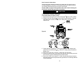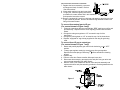
1
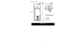
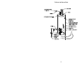
GAS WATER HEATER A Spanish language version of these instructions is available by contacting the company listed on the rating plate. La versión espãnola de estas instrucciones se puede obtener al escribirle a la fábrica cuyo nombre aparece en la placa de especificaciones. MANUFACTURED HOME (MOBILE HOME) CLOSED COMBUSTION (DIRECT VENTING) INSTALLATION AND OPERATING INSTRUCTION MANUAL WARNING: If the information in these instructions is not followed exactly, a fire or explosion may result causing property damage, personal injury or death. FOR YOUR SAFETY Do not store or use gasoline or other flammable, combustible, or corrosive vapors and liquids in the vicinity of this or any other appliance. WHAT TO DO IF YOU SMELL GAS Do not try to light any appliance. Do not touch any electrical switch; do not use any phone in your building. Immediately call your gas supplier from a neighbor’s phone. Follow the gas supplier's instructions. If you cannot reach your gas supplier, call the fire department. Installation and service must be performed by a qualified installer, service agency or the gas supplier. For your family’s comfort, safety and convenience we recommend water heaters be installed and serviced by a plumbing professional. 238-37281-00U REV 04/11 CONGRATULATIONS! You have just purchased one of the finest water heaters on the market today! This installation, operation and instruction manual will explain in detail the installation and maintenance of your new Mobile Home Water Heater. We strongly recommend that you contact a plumbing professional for the installation of this water heater. We require that you carefully read this manual, as well as the enclosed warranty, and refer to it when questions arise. If you have any specific questions concerning your warranty, please consult the plumbing professional from whom your water heater was purchased. For your records we recommend that you write the model, serial number and installation date of your water heater in the maintenance section in the back of this manual. This manual should be kept with the water heater. 2 TABLE OF CONTENTS Page GENERAL INFORMATION ............................................................................. 4 INSTALLATION .............................................................................................. 5 Locating the Water Heater ..................................................................... 5 Minimum Clearances.............................................................................. 7 Drain Pan Installation ............................................................................. 9 Combustion Air Supply........................................................................ 10 Venting................................................................................................... 11 Water Connections ............................................................................... 12 Gas Connections .................................................................................. 15 Gas Conversion Instructions .............................................................. 16 GENERAL OPERATION ............................................................................... 20 Lighting and Shutdown Instructions.................................................. 21 Burner Flame Check............................................................................. 24 MAINTENANCE ............................................................................................ 24 TYPICAL INSTALLATION ............................................................................ 27 GAS FIRED MANUFACTURED HOME ....................................................... 28 PARTS LIST .................................................................................................. 28 3 GENERAL INFORMATION This water heater must be installed in accordance with The Federal Manufactured Home Construction And Safety Standard (H.U.D. Title 24, Part 3280.707d2) or CAN/CSA Z240 MH series, mobile home. In the absence of such a standard, the water heater should be installed in accordance with the Standard For Mobile Homes (ANSI/NFPA NO. 501-B1977). The warranty for this water heater is in effect only when the water heater is installed, adjusted, and operated in accordance with these Installation and Operating Instructions. The manufacturer will not be liable for any damage resulting from alteration and/or failure to comply with these instructions. This water heater is of the closed combustion type (direct venting) where all the combustion air is supplied from the outdoors through the air intake and all combusted gas products are vented directly to the outside by means of the roof jack. No draft diverter (vent hood) is required for this water heater. Underwriters Laboratories, Inc. has tested a representative sample of this water heater design for its safety of operation. The UL listing of this water heater includes the field installation of the following components: roof jack, air intake tube, and heater tie down materials. These components for field installation may have been shipped with this heater and must be installed according to these instructions (see figure 1). No other components are approved for use with this water heater. This water heater has been designed and certified for the purpose of heating potable water. The installation and use of this water heater for any purpose other than the heating of potable water may cause damage to the water heater, create a hazardous condition, and nullify the warranty. CAUTION Incorrect operation of this appliance may create a hazard to life and property and will nullify the warranty. Do not use this appliance if any part has been submerged in water. You should contact the plumbing professional who installed the water heater to inspect the appliance and to replace any part of the control system including the combination gas control which has been submerged in water. IMPORTANT Before proceeding, please inspect the water heater and components for possible damage. DO NOT install any damaged components. If damage is evident then please contact the supplier where the water heater was purchased or the manufacturer listed on the rating plate for replacement parts. 4 General Information continued- This water heater has been manufactured for operation at altitudes from sea level to 2000 feet (610m) (unless otherwise specified on the water heater). For use of this appliance at an elevation greater than 2000 feet (610m), contact the dealer or manufacturer listed on the rating plate for information on any necessary modification. Uncorrected operation of this appliance may create a hazard to life and property. DANGER Do not store or use gasoline or other flammable, combustible, or corrosive vapors and liquids in the vicinity of this or any other appliance. Make sure to check the rating plate and combination gas control on the water heater to be certain that the type of gas being supplied corresponds with the marking on the rating plate and combination gas control. A sacrificial anode is used to extend tank life. The removal of this anode, for any reason, will nullify the warranty. In areas where water is unusually active, an odor may occur at the hot water faucet due to a reaction between the sacrificial anode and the impurities in the water. If this should happen, an alternative anode may be purchased from the supplier that installed this water heater. This will minimize the odor while protecting the tank. Additionally, the water heater should be flushed with appropriate dissolvers to eliminate any bacteria. INSTALLATION Locating the Water Heater This water heater MUST NOT be installed in any location where gasoline or flammable vapors are likely to be present, unless the installation is such to eliminate the probable ignition of gasoline or flammable vapors. The location of this water heater is of the utmost importance. Before installing this water heater, read the Installation section of these instructions. DO NOT locate the water heater where water lines could be subjected to freezing temperatures. Make sure the cold water pipes are not located directly above the gas control so that condensate during humid weather does not drip on the controls. WARNING Water heaters are heat producing appliances. To avoid damage or injury there must be no materials stored against the water heater or vent-air intake system and proper care must be taken to avoid unnecessary contact (especially by children) with the water heater and vent-air intake components. UNDER NO CIRCUMSTANCES MAY FLAMMABLE MATERIALS, SUCH AS GASOLINE OR PAINT THINNER BE USED OR STORED IN THE VICINITY OF THIS WATER HEATER, VENT-AIR INTAKE SYSTEM OR IN ANY LOCATION FROM WHICH FUMES COULD REACH THE WATER HEATER OR VENTAIR INTAKE SYSTEM. 5 Installation (Locating The Water Heater) continued- Water heater corrosion and component failure can be caused by the heating and breakdown of airborne chemical vapors. Examples of some typical compounds that are potentially corrosive are: spray can propellants, cleaning solvents, refrigerator and air conditioning refrigerants, swimming pool chemicals, calcium and sodium chloride, waxes and process chemicals. These materials are corrosive at very low concentration levels with little or no odor to reveal their presence. NOTE: DAMAGE TO THE WATER HEATER CAUSED BY EXPOSURE TO CORROSIVE VAPORS IS NOT COVERED BY THE WARRANTY. DO NOT OPERATE THE WATER HEATER IF EXPOSURE HAS OR WILL OCCUR. DO NOT STORE ANY POTENTIALLY CORROSIVE COMPOUNDS IN THE VICINITY OF THE WATER HEATER. For exact venting specifications, please consult the Venting section of these Installation and Operating Instructions. It is recommended that a minimum clearance of 4 inches (10.2 cm) be provided on the side of the water heater for servicing and maintenance of the combination temperature and pressure relief valve. WARNING DO NOT ATTEMPT TO LIGHT ANY GAS APPLIANCE IF YOU ARE NOT CERTAIN OF THE FOLLOWING: • Liquefied petroleum gases/propane gas and natural gas have an odorant added by the gas supplier that aids in detection of the gas. • Most people recognize this odor as a “sulfur” or “rotten egg” smell. • Other conditions, such as “odorant fade” can cause the odorant to diminish in intensity, or “fade”, and not be as readily detectable. • If you have a diminished sense of smell, or are in any way unsure of the presence of gas, immediately contact your gas supplier from a neighbor’s telephone. • Gas detectors are available. Contact your gas supplier or plumbing professional for more information. WARNING Liquefied petroleum gases/propane gases are heavier than air and will remain at floor level if there is a leak. Basements, crawl spaces, closets and areas below ground level will serve as pockets for accumulation of leaking gas. Before lighting, smell all around the appliance area for gas. Be sure to smell next to the floor. IF YOU SMELL GAS: • Do not try to light any appliance. • Do not touch any electric switch; do not use any telephone in your building. • Immediately call your gas supplier from a neighbor’s telephone. Follow the gas supplier’s instructions. • If you cannot reach your gas supplier, call the fire department. DO NOT OPERATE APPLIANCE UNTIL LEAKAGE IS CORRECTED! 6 Installation (Locating The Water Heater) continued- This water heater MUST be installed indoors out of the wind and weather. This water heater must be located in an area where leakage of the tank, water line connections, or the combination temperature and pressure relief valve will not result in damage to the area adjacent to the water heater or to lower floors of the structure. When such locations cannot be avoided, a suitable drain pan must be installed under the water heater (Refer to drain pan installation section for more information.). The drain pan must have a minimum length and width of at least 4 in. (10.2 cm) greater than the diameter of the water heater and must not restrict proper combustion air flow to the water heater. The drain pan, as described above, can be purchased from your plumbing professional. The drain pan must be piped to an adequate drain. The piping must be at least 3/4 inch (1.9 cm) in diameter and pitched for proper drainage. To comply with NSF requirements this water heater is to be: a) Sealed to the floor with sealant, in a smooth and easily cleanable way, or b) Installed with an optional leg kit that includes legs and/or extensions that provide a minimum clearance of 6” beneath the water heater. Note: For California installation this water heater must be braced, anchored, or strapped to avoid falling or moving during an earthquake. See instructions for correct installation procedures. Instructions may be obtained from the DSA Headquarters Office, 1102 Q Street, Suite 5100, Sacramento, CA 95811. Minimum Clearances WARNING Failure to adhere to these installation and operating instructions may create a hazard to life and property and will nullify the warranty. This installation shall allow access to the front of the water heater and adequate clearance shall be provided for servicing and operating this water heater. The water heater may be installed on either a combustible or noncombustible floor. If the water heater is to be installed directly on carpeting, it shall be installed on top of a metal or wood panel (or equivalent) extending beyond the full width and depth of the appliance by at least 3 inches (7.6 cm) in any direction or, if the appliance is to be installed in an alcove or closet, the entire floor shall be covered by the panel. 7 Installation continued- Figure 1 Minimum Clearances From Combustible Materials A 0” (0cm) B 0” (0cm) C 3” (7.62cm) D 78” (1.98mm) VENT ---- IMPORTANT The flow of combustion and ventilating air must not be obstructed. 8 Drain Pan Installation for non-flammable vapor ignition resistant manufactured home water heaters 1. 2. 3. 4. 5. This section is intended for use with non-flammable vapor ignition resistant manufactured home water heaters that will be installed in an application where a drain pan is required. After hole is cut in floor and underside sheathing, and before the water heater is installed, prepare drain pan. Locate and cut a 3-1/2” diameter hole in drain pan at 4-1/2” from center (see Figure 2). This hole will be located at the front of the water heater upon final installation. Align drain pan hole with hole cut in floor and underside sheathing for air intake. Apply 4” diameter circle of silicone around bottom of air intake plate and screws used to secure air intake to floor for proper water tight sealing (see Figure 3). CAUTION Silicone has a strong odor and should have adequate ventilation until cured. Refer to the manufacturer’s instructions for adequate drying time. 6. Continue proper installation per this installation and operation manual and the roof jack & air intake installation instructions provided with the roof jack kit. Be sure to apply silicone around screws used to secure the water heater to the floor through the drain pan for proper water tight sealing. Figure 2 Figure 4 Figure 3 9 Combustion Air Supply All combustion air must be supplied from outdoors by one of the following installation methods and as illustrated in Figure 5. The flow of combustion and ventilating air must not be obstructed. Adequate air must be supplied for combustion and ventilation. An insufficient supply of air will cause recirculation of combustion products resulting in air contamination that may be hazardous to life. Such a condition often will result in a yellow, luminous burner flame, causing carboning or sooting of the combustion chamber, burners and flue tubes with possible damage to the heater. AIR INTAKE INSTALLATION - 3” (7.6cm) diameter telescoping air intake and leg enclosure are required to supply fresh air to the water heater for combustion kit P/N 239-37025-01 for 30 gallon (113.5L) water heaters and 23937025-02 for 40 gallon (151.4L) water heaters. Note: When a mobile home is tightly skirted, an air inlet opening in the skirting must be provided. The opening shall have a minimum free area of at least 9 in2 (22.9cm2). If the opening is screened or covered with a louver, the total free area must be at least 9 in2 (22.9cm2). The following steps must be followed for proper installation of these air supply components: (Refer to Figure 5). 10 Combustion air supply continued- 1. After selecting the proper location for the water heater, cut a 4” (10.2cm) diameter hole through the floor and all other layers of flooring and sheathing directly beneath the front center of the water heater. 2. Insert the air intake into the 4” (10.2cm) diameter hole and fasten to the floor with the screws provided. 3. Adjust the air intake so the lower tube extends below the underside sheathing and secure with the screws provided. THE BOTTOM OF THE AIR INTAKE MUST BE AT LEAST 12” (30.5cm) ABOVE THE GROUND LEVEL. 4. Seal the openings around the air intake and underside sheathing to resist the entrance of rodents. 5. Position the water heater so it is centered above the air intake. (Note: The water heater should also be centered with the openings in the roof and ceiling to allow for correct assembly of the roof jack to the flue tube.) The water heater is to be secured in place using the supplied sheet metal strapping and screws. Fasten the base of the water heater to the floor using the screws provided. The perforated metal strapping must be fastened to the top of the water heater and to the adjacent walls with the screws provided. (See Figure 5) Venting WARNING The vent system must be installed properly. Failure to properly install the vent system could result in property damage, personal injury, or death. Make certain the flue baffle is in place and centered in the flue tube. Cut a 7 1/4 inch (18.5cm) diameter hole in the ceiling and roof directly above the flue of the water heater. Center the water heater beneath the 7 1/4 inch (18.5cm) diameter hole in the roof and ceiling for proper alignment of the flue tube and roof jack vent. Apply non-hardening mastic on the roof, around the previously cut hole, to form a weather seal with the flashing of the gas vent roof jack assembly. Note: Only the roof jacks listed in Figure 5 can be used on this water heater. Insert the 3 inch (7.62 cm) vent connector extension (shipped telescoped) into the gas vent roof jack assembly and down onto the flue pipe extruding from the top of the water heater. Fasten the 3 inch (7.62 cm) vent connector to the flue pipe using the 3 inch (7.62 cm) clamp provided. After all connections are made, apply a bead of silicone (supplied with vent kit) to all vent seams and connections above the flue pipe (some kits may contain silicone bands to seal vent joints). 11 Installation (Venting) continued- Roof flashing (secure per instructions supplied) Roof 2" (5.1cm) REF Ceiling Figure 5 Silicone Bands Hot water outlet Temperature & Pressure Relief Valve Perforated straping (shipped in carton) secure to enclosure walls and to top of heater. Enclosure Cold water inlet Gas Conversion package Drain Valve Fasten water heater base to the floor with screws provided. Floor Water Connections NOTE: BEFORE PROCEEDING WITH THE INSTALLATION, CLOSE THE MAIN WATER SUPPLY VALVE. After shutting off the main water supply, open a faucet to relieve the water line pressure to prevent any water from leaking out of the pipes while making the water connections to the water heater. After the pressure has been relieved, close the faucet. The COLD water inlet and HOT water outlet are identified on the top of the water heater. The fittings at the cold water inlet and hot water outlet are dielectric waterway fittings with 3/4” NPT male thread. Make the proper plumbing connections between the water heater and the plumbing system to the house. Install a shut-off valve in the cold water supply line. CAUTION If sweat fittings are to be used, DO NOT apply heat to the nipples on top of the water heater. Sweat the tubing to the adapter before fitting the adapter to the water connections. It is imperative that heat is not applied to the nipples containing a plastic liner. WARNING FAILURE TO INSTALL AND MAINTAIN A NEW, LISTED 3/4” X 3/4” TEMPERATURE AND PRESSURE RELIEF VALVE WILL RELEASE THE MANUFACTURER FROM ANY CLAIM WHICH MIGHT RESULT FROM EXCESSIVE TEMPERATURE AND PRESSURES. 12 Water connections continuedIf this water heater is installed in a closed water supply system, such as the one having a back-flow preventer in the cold water supply, provisions shall be made to control thermal expansion. DO NOT operate this water heater in a closed system without provisions for controlling thermal expansion. Your water supplier or local plumbing inspector should be contacted on how to control this situation. After installation of the water lines, open the main water supply valve and fill the water heater. While the water heater is filling, open several hot water faucets to allow air to escape from the water system. When a steady stream of water flows through the faucets, close them and check all water connections for possible leaks. NEVER OPERATE THE WATER HEATER WITHOUT FIRST BEING CERTAIN IT IS FILLED WITH WATER. WARNING For protection against excessive temperatures and pressure, install temperature and pressure protective equipment required by local codes, but not less than a combination temperature and pressure relief valve certified by a nationally recognized testing laboratory that maintains periodic inspection of production of listed equipment or materials as meeting the requirements of the Standard for Relief Valves and Automatic Gas Shutoff Devices for Hot Water Supply Systems, ANSI Z21.22 or the Standard CAN1-4.4. Temperature and Pressure and the Standard CAN1-4.4, Temperature, Pressure, Temperature and Pressure Relief Valves and Vacuum Relief Valves. The combination temperature and pressure relief valve shall be marked with a maximum set pressure not to exceed the maximum working pressure of the water heater. The combination temperature and pressure relief valve shall also have an hourly rated temperature steam BTU discharge capacity not less than the hourly rating of the water heater. Install the combination temperature and pressure relief valve into the opening provided and marked for this purpose on the water heater. Note: Some models may already be equipped or supplied with a combination temperature and pressure relief valve. Verify that the combination temperature and pressure relief valve complies with local codes. If the combination temperature and pressure relief valve does not comply with local codes, replace it with one that does. Follow the installation instructions above on this page. Install a discharge line so that water discharged from the combination temperature and pressure relief valve will exit within six (6) inches (15.2 cm) above, or any distance below the structural floor and cannot contact any live electrical part. The discharge line is to be installed to allow for complete drainage of both the combination temperature and pressure relief valve and the discharge line. The discharge opening must not be subjected to blockage or freezing. DO NOT thread, plug or cap the discharge line. It is recommended that a minimum clearance of four (4) inches (10.2 cm) be provided on the side of the water heater for servicing and maintenance of the combination temperature and pressure relief valve. Do not place a valve between the combination temperature and pressure relief valve and the tank. 13 Water Connections continued- WARNING Hydrogen gas can be produced in an operating water heater that has not had water drawn from the tank for a long period of time (generally two weeks or more). Hydrogen gas is extremely flammable. To prevent the possibility of injury under these conditions, we recommend the hot water faucet to be open for several minutes at the kitchen sink before you use any electrical appliance, which is connected to the hot water system. If hydrogen is present, there will be an unusual sound such as air escaping through the pipes as hot water begins to flow. Do not smoke or have open flame near the faucet at the time it is open. This water heater can deliver scalding temperature water at any faucet in the system. Be careful whenever using hot water to avoid scalding injury. Certain appliances such as dishwashers and automatic clothes washers may require increased temperature water. By setting the thermostat on this water heater to obtain the increased temperature water required by these appliances, the potential for scald injury increases. To protect against injury, you should install an ASSE approved mixing valve in the water system. This valve will reduce point of discharge temperature by mixing cold and hot water in branch supply lines. Such valves are available from the manufacturer of this water heater or a local plumbing supplier. Please consult with a plumbing professional. Water temperature over 125°F can cause severe burns instantly or death from scalds. Children, disabled and elderly are at highest risk of being scalded. Review this instruction manual before setting temperature at water heater. Feel water before bathing or showering. Temperature limiting valves are available. APPROXIMATE TIME/TEMPERATURE RELATIONSHIPS IN SCALDS 120°F (49°C) More than 5 minutes 125°F (52°C) 1½ to 2 minutes 130°F (54°C) About 30 seconds 135°F (57°C) About 10 seconds 140°F (60°C) Less than 5 seconds 145°F (63°C) Less than 3 seconds 150°F (66°C) About 1½ seconds 155°F (68°C) About 1 second 14 Gas Connections The gas supply lines must meet all requirements of the National Fuel Gas Code (ANSI Z223.1-Latest Edition), or in Canada CAN/CGA B149.1 Natural Gas Installation Code (Latest Edition) or CAN/CGA B149.2 Propane Installation Code (Latest Edition). The minimum permissible gas supply pressure for the purpose of input adjustment is one (1.0) inch (0.25 kPa) water column above the operating manifold pressure. See the rating plate and gas valve for the manifold pressure and gas type. The maximum permissible gas supply pressure is fourteen (14.0) inches (3.5 kPa) water column for natural gas and liquefied petroleum gases/propane gas. 1. Connect this water heater only to the type of gas (Natural or Propane gas) as shown on the rating plate. Use clean black iron pipe or equivalent material approved by local codes and ordinances. (Dirt and scale from the pipe can enter the gas valve and cause it to malfunction). The inlet gas line must have a minimum length of three (3) inches (7.6 cm) drip leg (sediment trap) installed as close to the water heater’s gas valve as possible. A ground joint union must be installed as close to the water heater as possible in the gas supply line feeding the water heater to permit servicing of the water heater. Compounds used on the threaded joints of the gas piping must be resistant to the action of liquefied petroleum gases/propane gas. DO NOT apply pipe dope to the gas valve inlet and make certain that no pipe dope has become lodged in the inlet screen of the gas valve. Extreme care must be taken to ensure no pipe dope enters the gas valve. Avoid excessive torque when tightening the gas supply line to the gas valve. Excessive torque may result in cracking of the gas valve housing and could create a gas leak. When tightening gas supply line to L.P. control, it is recommended to hold the inlet body of the control securely with an adequate wrench. The suggested maximum torque is 31.5 ft. lbs. (4.4 kg-m). WARNING The manufacturer of this water heater will not be liable for any damage or injury caused as a result of a cracked gas inlet as a result of excessive torque. 2. This water heater and its gas connection must be leak tested before placing the water heater in operation. Check for gas leaks with a soap and water solution and a brush or a commercial leak detector fluid. NEVER USE A MATCH OR OPEN FLAME FOR TESTING! CAUTION The water heater and individual shutoff valve must be disconnected from the gas supply piping system during any pressure testing of the system at test pressures in excess of 1/2 psi (3.5 kPa). The water heater must be isolated from the gas supply piping system by closing its manual shutoff valve during any pressure testing of the gas supply system at test pressures equal to or less than 1/2 psi (3.5 kPa). The supply line must be capped when not connected to the water heater. 3. While checking for leaks care must be taken to prevent solution from contacting the electrical connections at the control. If electrical connections at the control become wet, they must be thoroughly dried before attempting to operate the water heater. 15 Gas Conversion Instructions Unless specifically ordered for operation on natural gas, this water heater is normally equipped for operation on liquefied petroleum (LP) gas but may be converted by following these gas conversion instructions. Caution: Make sure gas to be supplied to this water heater following the conversion matches the gas being converted to. CAUTION All gas conversions must be performed by qualified service personnel only. To convert from LP gas to natural gas (For control shown in Figure 6 only) to the “OFF” position. 1. Depress and rotate gas control knob clockwise 2. Change main gas regulator by removing cap from gas regulator. Depress and rotate knob clockwise to NAT. setting using a screwdriver. Replace cap. Figure 6 3. Change the pilot regulator by removing pilot regulator cap. Depress and rotate knob counterclockwise to the NAT. setting using a screwdriver. Replace cap. 4. Remove the outer door. Remove, or slide open, the inner door. 5. Disconnect thermocouple, gas supply tube and pilot tube from the gas valve and remove the burner assembly from the water heater. 6. Remove the “RED” color coded L.P. orifice and pilot assembly and replace with natural gas orifice and pilot assembly provided in the cloth bag attached to the water heater. 16 Gas Conversion Instructions continued- 7. Replace the burner assembly, reconnect all fittings and check for leaks. Refer to “Gas Connections”. 8. Close and/or replace inner and outer doors. 9. To light pilot, follow the lighting instructions provided on the water heater and in this installation and operation instruction manual. 10. Remove “equipped for” card from cloth bag and attach to gas piping as close to gas control as possible. Remove and discard tag attached to water inlet fitting of the water heater. To convert from natural gas to LP gas (For control shown in Figure 6 only) 1. Follow the instructions above except add the “RED” main burner orifice and pilot assembly. Replace with the ones originally provided with the water heater. 2. Change the main gas regulator to “LP” as noted in step 2 of the instructions. 3. Change the pilot regulator to “LP” as noted in step 3 of the instructions. 4. Replace “equipped for” tag with tag supplied in cloth bag for gas being used. To convert from LP gas to natural gas (For control shown in Figure 7 only) 1. Rotate and partially depress gas control knob clockwise to “OFF” position. 2. Change gas regulator setting by removing cap from gas regulator. Depress and rotate plunger clockwise with a screwdriver releasing plunger. 3. Replace cap. 4. Remove outer door. Remove and/or slide open inner door. 5. Disconnect thermocouple, gas supply tube, and pilot from gas valve and remove burner assembly from water heater. 6. Remove “RED” color coded main burner orifice and pilot assembly and replace with orifice and pilot assembly provided in cloth bag attached to the water heater. Figure 7 17 Gas Conversion Instructions continued- 7. Replace the burner assembly and reconnect all fittings and check for leaks. Refer to “Gas Connections”. 8. Close and/or replace inner and outer doors. Note: For closed combustion product, make sure screws are tight and seal is made around gas supply tube to burner. 9. To light pilot, follow the lighting instructions provided on the water heater and in this installation and operation instruction manual. 10. Remove “equipped for” card from cloth bag and attach to gas piping as close to gas control as possible. Remove and discard tag attached to water inlet fitting of the water heater. To convert from natural gas to LP gas (For control shown in Figure 7 only) 1. Follow the instructions above except remove cap from gas regulator, and depress and rotate plunger counterclockwise 2. Remove main burner orifice and pilot assembly and replace with “RED” color coded L.P. orifice and pilot assembly provided in cloth bag attached to the water heater. 3. Replace “equipped for” tag with tag supplied in cloth bag for gas being used. To convert from L.P. gas to natural gas (For control shown in Figure 8 only) 1. Rotate and partially depress gas control knob clockwise to “OFF” position. 2. Remove the plastic cover from the regulator cap, revealing threads. The letters “LP” and “NAT” with arrows will be visible. 3. Using an open-ended wrench, turn the regulator cap counter clockwise , until it comes off. Turn the regulator cap around so the arrow next to “NAT” is facing toward the gas valve. Reinstall the regulator cap by turning it clockwise , until tight. 18 Gas Conversion Instructions continuedGAS CONTROL KNOB APPROXIMATELY 120°F (48.9°C) GAS REGULATOR APPROXIMATELY 160°F (48.9°C) Figure 8 APPROXIMATELY 85°F (71.1°C) LP GAS SETTING GAS CONTROL KNOB SHOWN IN "OFF" POSITION NATURAL GAS SETTING Replace the plastic cover. Disconnect thermocouple, gas supply tube and pilot tube from the gas valve and remove the burner assembly from the water heater. 6. Remove the “RED” color coded L.P. orifice and pilot assembly and replace with natural gas orifice and pilot assembly provided in the cloth bag attached to the water heater. 7. Replace the burner assembly, reconnect all fittings and check for leaks. Refer to “Gas Connections”. 8. Replace inner doors with the following procedure. 9. To light pilot, follow the lighting instructions provided on the water heater and in this installation and operation instruction manual. 10. Remove “equipped for” card from cloth bag and attach to gas piping as close to gas control as possible. Remove and discard tag attached to water inlet fitting of the water heater. 4. 5. To convert from natural gas to L.P. gas (For control shown in Figure 8 only) 1. Follow the instructions above except add the “RED” main burner orifice and pilot assembly. Replace with the ones originally provided with the water heater. 2. Change the pilot regulator to “LP” as noted in step 3 of the instructions. 3. Replace “equipped for” tag with tag supplied in cloth bag for gas being used. 19 GENERAL OPERATION WARNING Water heaters are heat producing appliances. To avoid damage or injury there shall be no materials stored against the water heater or vent-air intake system, and proper care shall be taken to avoid unnecessary contact (especially by children) with the water heater and vent-air intake system. UNDER NO CIRCUMSTANCES SHALL FLAMMABLE MATERIALS, SUCH AS GASOLINE OR PAINT THINNER BE USED OR STORED IN THE VICINITY OF THIS WATER HEATER, VENT-AIR INTAKE SYSTEM OR IN ANY LOCATION FROM WHICH FUMES COULD REACH THE WATER HEATER OR VENT-AIR INTAKE SYSTEM. TO FILL THE WATER HEATER 1. Close the water heater drain valve by turning the knob clockwise. 2. Open the cold water supply shut-off valve. 3. Open several hot water faucets to allow air to escape from the system. 4. When a steady stream of water flows from the faucets, the water heater is filled. Close the faucets and check for water leaks at the water heater drain valve, combination temperature and pressure relief valve and the hot and cold water connections. TO DRAIN THE WATER HEATER Should it become necessary to completely drain the water heater, make sure you follow the steps below: 1. Rotate the thermostat dial to the lowest position. 2. Rotate and partially depress gas control knob clockwise to the “OFF” position. 3. Shut off the gas supply to the water heater. 4. Close the cold water supply shut-off valve. 5. Open the drain valve on the water heater by turning the knob counterclockwise . The drain valve has threads on the end that will allow the connection of a standard hose coupling. 6. Open a hot water faucet to allow air to enter the system. To refill the water heater, refer to “To Fill the Water Heater.” 20 Lighting and Shutdown Instructions 21 Thermostat Adjustment Figure 9 The thermostat dial is set to its lowest temperature setting when shipped from the factory. Remember that lower temperature settings are more energy efficient. Adjust the temperature by turning the thermostat dial. It is suggested that the starting point setting not be greater than the ” “ mark on the thermostat dial (approximately 120°F [48.9°C]) as pictured above. Rotate the thermostat dial clockwise to decrease the temperature setting. Rotate the thermostat dial counter-clockwise to increase the temperature setting. Adjust the dial until the minimum acceptable temperature is achieved (See Figure 9 above for approximate temperature settings). Figure 10 The thermostat dial is set to its lowest temperature setting when shipped from the factory. Remember that lower temperature settings are more energy efficient. Adjust the temperature by turning the thermostat dial. It is suggested that the starting point setting not be greater than the “ ” mark on the thermostat dial (approximately 120°F [48.9°C]) as pictured above. Rotate the thermostat dial counter-clockwise to decrease the temperature setting. Rotate the thermostat dial clockwise to increase the temperature setting. Adjust the dial until the minimum acceptable temperature is achieved (See Figure 10 above for approximate temperature settings). 22 Thermostat Adjustment ContinuedGAS CONTROL KNOB TERMOSTAT TEMP. DIAL GAS REGULATOR APPROXIMATELY 120°F (48.9°C) APPROXIMATELY 160°F (48.9°C) APPROXIMATELY 85°F (71.1°C) Figure 11 The thermostat dial is set to its lowest temperature setting when shipped from the factory. Remember that lower temperature settings are more energy efficient. Adjust the temperature by turning the thermostat dial. It is suggested that the starting point setting not be greater than the ” “ mark on the thermostat dial (approximately 120°F [48.9°C]) as pictured above. Rotate the thermostat dial clockwise to decrease the temperature setting. Rotate the thermostat dial counter-clockwise to increase the temperature setting. Adjust the dial until the minimum acceptable temperature is achieved (See Figure 11 above for approximate temperature settings). 23 General Operation continued- DANGER Hotter water increases the risk of scald injury. Scalding may occur within five (5) seconds at a temperature setting of 140 F (60 C). To protect against hot water injury, install an ASSE approved mixing valve in the water system. This valve will reduce point of discharge temperature by mixing cold and hot water in branch water lines. A licensed plumbing professional or local plumbing authority should be consulted. Note: This water heater is equipped with an energy cut out device to prevent overheating. Should overheating occur or the gas supply fail to shut off, turn off the manual gas control valve to the appliance and call a qualified service technician. Note: Whenever the water heater is filled with cold water, condensate will form on the cool tank surface and drops of water will fall on the hot burner and combustion chamber surfaces producing a “sizzling” noise. Condensation is normal and does not indicate a leak. It will disappear when the tank becomes heated. Burner Flame Check Steel Burner: These models are equipped with self adjusting air mixture and do not have an adjustable air shutter (See Figure 12). At periodic intervals, a visual check of the main burner and pilot flames should be made to determine if they are burning properly. The main burner flame should light smoothly from the pilot. Figure 12 MAINTENANCE IMPORTANT The water heater should be inspected at a minimum annually by a qualified service technician for damaged components and/or joints not sealed. DO NOT operate this water heater if any part is found damaged or if any joint is found not sealed. The following maintenance should be performed by a qualified service technician at the minimum periodic intervals suggested below. In some installations, the maintenance interval may be more frequent depending on the amount of use and the operating conditions of the water heater. 24 Maintenance Continued- Regular inspection and maintenance of the water heater and vent-air intake system will help to insure safe and reliable operation. 1. Annually check the operation of the thermostat. 2. The flow of combustion and ventilation air MUST NOT be restricted. Clear the combustion air openings of any dirt, dust, or other restrictions. WARNING The ventilation air system may be HOT. 3. At all times keep the water heater area clear and free from combustible materials, gasoline and other flammable vapors and liquids. 4. Bi-annually conduct a visual check of the main and pilot burner flames to determine that they are burning properly. See Burner Flame Check section. 5. Annually remove the inner door and main burner assembly to clean orifices and related parts of any dirt or other foreign material. Inspect the burner ports for obstructions or debris and clean with a wire brush as needed. Wire brush and/or vacuum clean the combustion chamber as needed to remove scale deposits and debris. NOTE: It is imperative for proper operation of the water heater that the inner door be replaced in the original location. WARNING When lifting the lever of the combination temperature and pressure relief valve, hot water will be released under pressure. Be careful that any released water does not result in bodily injury or property damage. 6. At least once a year, check the combination temperature and pressure relief valve to insure that the valve has not become encrusted with lime. Lift the lever at the lever at the top of the valve several times until the valve seats properly without leaking and operates freely. 7. Monthly drain off a gallon of water to remove silt and sediment. WARNING THIS WATER MAY BE HOT. If the combination temperature and pressure relief valve on the appliance discharges periodically, this may be due to thermal expansion in a closed water supply system. Contact the water supplier or local plumbing inspector on how to correct this situation. Do not plug the combination temperature and pressure relief valve outlet. 9. A combination sacrificial anode rod/hot water outlet nipple has been installed to extend tank life. The anode rod should be inspected periodically and replaced when necessary to prolong tank life. Water conditions in your area will influence the time interval for inspection and replacement of the anode rod. 8. 25 Maintenance Continued- Contact the plumbing professional that installed the water heater or the manufacturer listed on the rating plate for anode replacement information. The use of a water softener may increase the speed of consumption. More frequent inspection of the anode is needed when using softened (or phosphate treated) water. The vent system must be inspected at least once a year to ensure against leakage of exhaust products. CAUTION FOR YOUR SAFETY, DO NOT ATTEMPT REPAIR OF COMBINATION GAS CONTROL, BURNERS OR GAS PIPING. REFER REPAIRS TO A QUALIFIED SERVICE TECHNICIAN. Contact your supplier or plumbing professional for replacement parts or contact the company at the address given on the rating plate of the water heater. Provide the part name, model and serial numbers of the water heater when ordering parts. READ THE WARRANTY FOR A FULL EXPLANATION OF THE LENGTH OF TIME THAT PARTS AND THE WATER HEATER ARE WARRANTED. Manufactured under one or more of the following U.S. Patents: RE.34,534; B1 5,341,770; 4,416,222; 4,628,184; 4,669,448; 4,672,919; 4,808,356; 4,829,983; 4,861,968; 4,904,428; 5,000,893; 5,023,031; 5,052,346; 5,081,696; 5,092,519; 5,115,767; 5,199,385; 5,277,171; 5,372,185; 5,485,879; 5,574,822; 5,596,952; 5,660,165; 5,682,666; 5,761,379; 5,943,984; 5,954,492; 5,988,117; 6,142,216; 6,684,821; 7,063,132; 6,395,280; 7,007,748; Other U.S. and Foreign patent applications pending. Current Canadian Patents: 1,272,914; 1,280,043; 1,289,832; 2,045,862; 2,092,105; 2,107,012; 2,108,186; 2,112,515 Complete the following information and retain for future reference: Model No: Serial No: Service Phone Days: Nights: Address: Supplier: Supplier Phone No: 26 TYPICAL INSTALLATION 27 GAS FIRED MANUFACTURED HOME (MOBILE HOME) PARTS LIST PARTS LIST & DESCRIPTION Gas Conversion Kit 12. Inner Door 13. Thermostat w/ECO 2. Jacket Top (Convertible-Nat. or L.P. Gas) 3. Fiberglass Insulation 14. Pilot Assembly 4. Glass Lined Tank 15. Gas Feed Line (Burner) 5. Tank Skirt Assembly 16. Main Burner Orifice 6. Jacket Base Assembly 17. Burner 7. Flue Baffle Assembly 18. Pilot Orifice (Not Shown) 8. Cold Water Inlet Tube w/Nipple 19. Outer Door 9. Magnesium Anode 20. Radiation Shield 10. Hot Water Outlet Nipple 21. T&P Relief Valve (Optional) 11. Drain Valve 22. Jacket 1. NOTE: Part description, part number, model and serial number and gas type must be specified when ordering service parts. 28