1
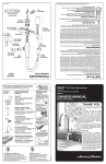
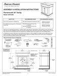
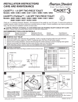
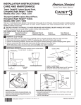
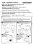
INSTALLATION INSTRUCTIONS
CARE AND MAINTENANCE
ABOVE COUNTER SINK FOR USE WITH: 0621.001 STUDIO
Thank you for selecting American Standard - the benchmark of fine quality for over 100 years. To ensure this product is installed properly, please read
these instructions carefully before you begin. (Certain installations may require professional help.) Also be sure your installation conforms to local codes.
! CAUTION: PRODUCT IS FRAGILE. TO AVOID BREAKAGE AND POSSIBLE INJURY HANDLE WITH CARE!
NOTE: Pictures may not exactly define contour of china and components.
RECOMMENDED FAUCET : 2064.101 ONE lavatory faucet
Log on to www.americanstandard-us.com for additional faucet selections.
*
*
RECOMMENDED TOOLS AND MATERIALS
Putty Knife
Hacksaw
Tubing Cutter
Regular Screwdriver
Phillips Screwdriver
Tape Measure
Adjustable Wrench
Pipe Wrench
Silicone Adhesive
Channel Lock Pliers
Basin Wrench
Plumber’s Putty or Caulking
Jig Saw
Drill
OBSERVE LOCAL PLUMBING AND BUILDING CODES
COUNTERTOP INSTALLATION
Perimeter
of
template
Perimeter of
template
Cut opening around the perimeter of the template.
6
3
Mount the faucet and drain
assembly (not included) on
the sink following the
manufacturer’s instructions.
Be certain to apply a bead
of sealing putty on the
underside of the drain (Part
“A”) in order to ensure a
watertight seal between the
sink and drain. Remove
excess putty after installing
drain on sink.
U S E
After checking fit
and alignment,
turn sink upside
down and apply a
generous portion
of silicone
adhesive around
the under side of
the rim near the
edge. Place sink in
position. Wipe off
excess adhesive.
Mounting holes are provided on the rear of the
lavatory so it can be secured to the wall if desired.
7
A
Connect supply line to
faucet (finger tight) and
carefully bend tubes to
engage with the supply
shut-off valves. Tighten
connections at faucet
and shut-off valves for
secure seal.
Shut-Off Valves
4
8
• Place the sink temporarily into the template.
• Check for alignment and clearance.
Connect trap to drain
assembly hand tight to
check alignment. It may
be necessary to cut off
part of the tailpiece (area
“B”) or part of the
horizontal leg of the trap
(area “C”). Secure joints
for watertight assembly.
B
C
• Mark the sink and countertop in several places
as a guide for the installation location.
Product names listed herein are trademarks of AS America, Inc.
© AS America, Inc. 2009
F U T U R E
Drill a clearance hole inside the perimeter line of the
template for countertop installation.
5
F O R
2
Using the template provided, locate the position of the sink
on the countertop. Provide proper clearance under the
countertop for the faucet supply lines, drain assembly and
the structural parts of the cabinet.
NOTE: If replacing an existing sink be certain to shut off
water supply before removing old sink.
S A V E
1
7 3 0 1 2 4 4- 1 0 0 R e v. A
VANITY INSTALLATION
4
1
Mounting holes are provided on the rear of the
lavatory so it can be secured to the wall if desired.
Assemble vanity as per instructions.
5
5
2
A
Shut-Off Valves
Mount the faucet and drain assembly
(not included) on the sink following the
manufacturer’s instructions. Be certain
to apply a bead of sealing putty on the
underside of the drain (Part “A”) in order
to ensure a watertight seal between the
sink and drain. Remove excess putty
after installing drain on sink.
Connect supply line to faucet (finger tight) and
carefully bend tubes to engage with the supply
shut-off valves. Tighten connections at faucet
and shut-off valves for secure seal.
6
3
• Place the sink on the vanity to check for alignment
and clearance.
• The sink should be centered left to right on the
vanity with the front edge of the sink even with the
front of the vanity.
B
C
• Secure sink to furniture as per vanity instructions.
Connect trap to drain assembly hand tight to
check alignment. It may be necessary to cut
off part of the tailpiece (area “B”) or part of the
horizontal leg of the trap (area “C”). Secure
joints for watertight assembly.
REPAIR PART NO.
DESCRIPTION
738990-0020A
CHROME OVERFLOW CAP
2
7 3 0 1 2 4 4 - 1 0 0 R e v. A