1
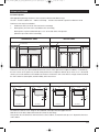
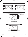
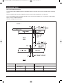
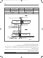
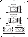
229062_Kindred_AMSD_DS_Farm_Undermount_A60001.qxd:Layout 1
7/8/11
11:36 AM
Page 1
INSTALLATION INSTRUCTIONS
GENERAL ADVICE
Please read these instructions before you begin installation.
1.
2.
3.
4.
5.
6.
7.
8.
Unpack the sink and inspect for any shipping damage before starting the installation.
Do not install a damaged unit.
American Standard accepts no liability for damage to the countertop, or sink fixture, during
installation.
Installation of this product may require custom cabinetry. We recommend that an experienced cabinet
maker build the new cabinet, or is responsible for modifications to existing cabinets, for this product.
To ensure a proper fit between the sink and the cabinet, and between the sink and the countertop
cut-out, and between the sink and any support framing, the fabricator/installer should have the actual
product in-hand.
Designer Series undermount sinks include a factory supplied masonite template to assist the
fabricator/installer when preparing the countertop cut-out. This template has been sized to create a
uniform reveal of the sink rim, and this reveal is recommended in order to compensate for the
dimensional variability of hand fabricated product. Any deviation from this recommendation is
certainly permissible, but must be based upon agreement between the customer and the
fabricator/installer … and any changes should be planned with the actual product in-hand for
dimensional verification.
The aesthetics of the installed product is of the utmost importance. Please take the necessary
care to ensure that any exposed silicone joints are kept to a minimum, the sink is properly
aligned to the cut-out, and excess silicone is cleaned from the sink.
This product is hand fabricated, and dimensions of the the product will vary from one unit to the
next. Industry accepted dimensional variance for this type of product is within 1/8".
Product specifications are available on our website at www.americanstandard-us.com
ITEMS SUPPLIED BY AMERICAN STANDARD
In addition to the Sink and Installation Instructions provided, American Standard has supplied the following
items within the sink package:
• 3 1/2" stainless steel sink strainer, one for each bowl
• 1/8" masonite template for undermount sinks
Call Customer Service
Technical Customer Service
Write Customer Service
1-800-442-1902
Monday through Friday
8:00 A.M. to 7:30 P.M. EST
1-800-442-1902
Monday through Friday
8:00 A.M. to 6:00 P.M. EST
Saturday
8:00 A.M. to 3:00 P.M. EST
Customer Care at American Standard
P.O. Box 6820
1 Centennial Plaza
Piscataway, NJ 08855-6820
A60001
0611
229062_Kindred_AMSD_DS_Farm_Undermount_A60001.qxd:Layout 1
7/8/11
11:36 AM
Page 2
FARMHOUSE SINKS
Installation Options
With appropriate planning, farmhouse sinks may be installed several different ways.
The sink ... the base cabinet unit ... and the countertop ... must be selected with a specific installation in mind.
Farmhouse sinks may be installed as:
1.
Undermount sinks (rim of the sink is below the countertop)
2.
Built-up sinks (rim of the sink is raised above the countertop)
Built-up sinks may be installed with up to 1 1/2" of the side of the sink exposed
(above the top surface of the countertop).
UNDERMOUNT SINKS
BUILT-UP SINKS
Countertop
Countertop
9" Sink Apron
9" Sink Apron
Farmhouse sinks may also be installed with the front corners of the apron flush to adjacent cabinets, or alternatively,
the front corners of the apron may extend out beyond the face of adjacent cabinets by as much as 1/2". We would
caution you to make allowance for installation of the faucet. Position the sink so that there is enough clearance behind
the sink to allow for a backsplash, and full mobility of the faucet lever.
LINEAR (STRAIGHT) FRONT
4 5/8"
19 3/8"
5 1/8"
5 1/8"
5
1818
7/8"
7/8"
BOW (CURVED) FRONT
111/8"
1
4"
4"4"
20"
20"
20"
5/8"
5/8"
4 1/2"
19 1/2"
33/4"
3/4"3
1 1/2"
2
24" Cabinet
Flush Front
24" Cabinet
Extended Front
1 1/4"
1/2"
1
24" Cabinet
Flush Front
24"24"
Cabinet
Cabinet
Extended Front
The farmhouse sink has a 3/4" flange on the underside of the apron that will support the unit.
Dab silicone to the base cabinet frame that will contact the sink flange.
Then position the unit either flush with the front face of the cabinet, or extend the unit up to 1/2" beyond the front face
of the cabinet.
2
A60001
0611
229062_Kindred_AMSD_DS_Farm_Undermount_A60001.qxd:Layout 1
7/8/11
11:36 AM
Page 3
FARMHOUSE SINKS
1 1/2"
20"
1 1/2"
16"
19 3/8"
2 1/2"
5/8"
20"
16"
20"
2 1/2"
3/4"
LINEAR (STRAIGHT) FRONT
BOW (CURVED) FRONT
Finished Wall
4 5/8" Straight
4" Curved
19 3/8"
Linear
24"
Cabinet
18 1/8"
Linear
20"
Bow
18 3/4"
Bow
5/8" Straight
Front Face
of Cabinet
R Reference Point
for Location
of Masonite
Template
3/4" Curved
FLUSH FRONT INSTALLATION
UNDERMOUNT SINK
Finished Wall
4 5/8" Straight
24"
Cabinet
4" Curved
19 13/8"
Linear
20"
Bow
F Face
Front
of Cabinet
5/8" Straight
3/4" Curved
FLUSH FRONT INSTALLATION
BUILT-UP SINK
A60001
0611
3
229062_Kindred_AMSD_DS_Farm_Undermount_A60001.qxd:Layout 1
7/8/11
11:36 AM
Page 4
UNDERMOUNT SINKS
Fabricator Template Preparation
The masonite template supplied by American Standard has been machined to the exact size and shape of the countertop
cut-out.
We recommend that this masonite template be used to create a female template from 1/2" plywood.
Use a router guide bushing and straight cutter bit to trace the masonite template onto 1/2" plywood, as indicated by
Figure 1, Part A, Template Preparation.
Sand the cut edge clean and smooth.
FIGURE 1
Part A
Part B
Part A
Router Guide
Bushing O.D.
4
Part B
Cutter Bit
Router Guide
Bushing O.D.
Cutter Bit
Recommended
3/8”
1/4”
1 9/64”
1/2”
Alternate
1/2”
1/4”
1”
1/4”
A60001
0611
229062_Kindred_AMSD_DS_Farm_Undermount_A60001.qxd:Layout 1
7/8/11
11:36 AM
Page 5
UNDERMOUNT SINK INSTALLATION ALTERNATIVE 1
Sink Installation Procedure
1.
Clamp the 1/2" plywood female template on the top surface of the countertop, in the desired position. This
position will be determined by the relationship of the sink rim to cabinet gables, cabinet supporting
members, and deck mounted fittings.
2.
Trace the edge of the template with the router guide bushing and straight cutter bit as indicated by
Figure 1, Part B, Template Preparation.
3.
Finish the cut-out edge with the desired router bit (ie. chamfer, bullnose, Roman ogee).
4.
Prepare a plywood reinforcement sheet that is the same material thickness as the countertop built-up and
big enough to cover the sink base cabinet frame. Use the 1/2" plywood template described earlier, to
cut-out the reinforcement sheet to accept the sink. Using a router, recess the plywood by .050" to .060" for
approximately 2" back from the cut-out, to accept the sink flange.
5.
Place this plywood reinforcement sheet on top of the sink base cabinet unit.
6.
Assemble sink strainers to sink.
7.
Clean sink rim and countertop mating surface with solvent.
8.
Lay sink in plywood reinforcement sheet and apply a continuous (translucent color) bead of silicone
around the sink rim.
9.
Lay the countertop on top of the cabinets and if necessary shift the sink so that it is centered within the
sink cut out.
10.
Align the sink to the cut-out so that a uniform reveal shows around the periphery of the cut-out.
11.
Use a non-abrasive cloth and solvent to remove excess silicone that has squeezed out beyond the
cut-out edge.
.050" / .060"
1/2" Plywood Sheet
Section Detail
Countertop
Sink Rim
1/2" Plywood
Cabinet Front
Silicone
A60001
0611
Section Detail
5
229062_Kindred_AMSD_DS_Farm_Undermount_A60001.qxd:Layout 1
7/8/11
11:36 AM
Page 6
UNDERMOUNT SINK INSTALLATION ALTERNATIVE 2
Sink Installation Procedure
1.
American Standard provides DXF files for this product at www.americanstandard-us.com. This outline of the
countertop cut-out is full scale and can be used to program CNC machinery. The cut-out has been designed to
crate a uniform reveal around the sink rim.
2.
Finish the cut-out edge with the desired router bit (ie, chamfer, bullnose, Roman ogee).
3.
Mount a support frame to adjacent cabinets.
A) The position of the frame members (dimensions X and Y) is determined by the sink cut-out location
(see figure). Check front to back dimensions for the sink cut out to ensure adequate clearance for the
faucet and possible use of a flip tray.
B) The elevation of the support frame (dimension Z) will be determined by the material thickness of the
countertop build-up, or substrate.
4.
Assemble sink strainers to sink.
5.
Clean sink rim and countertop mating surface with solvent.
6.
Apply a continuous (translucent color) bead of silicone around the sink rim.
7.
Drop sink into opening of support members.
8.
Lay countertop onto cabinets.
9.
Align the sink to the cut-out so that a uniform reveal shows around the periphery of the cut-out.
APPROX. 1/8 - 1/4" REVEAL
COUNTER TOP
"Z" BUILD-UP / SUBSTRATE
SILICONE
X
Y
"Z" ELEVATION
CABINET
SUPPORT FRAME
1/4" CLEARANCE
6
A60001
0611
ÉVIERS SOUS-MONTÉS (À INSTALLER SOUS LE COMPTOIR) POSSIBILITÉ D’INSTALLATION 2
Installation
Fixer une structure porteuse sur les armoires adjacentes.
3.
Finir le chant de l’ouverture au moyen de la fraise de toupie désirée (ex. : chanfrein, arrondi, doucine romaine).
2.
American Standard offre des fichiers DXF pour ce produit à l'adresse www.americanstandard-us.com. Ce profil
de la découpure de dessus de comptoir correspond à la grandeur réelle d’exécution et peut s’utiliser pour
programmer une machine à CNC. Cette découpure a été conçue pour laisser apparaître une bande uniforme sur
le périmètre du rebord de l’évier.
1.
A) La position des éléments de la structure (dimensions X sur Y) est déterminée par la position de la
découpe de l’évier (voir figure). Vérifier la distance entre le mur et l’évier pour s’assurer qu’il y a
suffisamment d’espace pour le robinet et possiblement un compartiment escamotable.
B) L’élévation de la structure porteuse (dimension Z) est déterminée par l’épaisseur de la cale du comptoir
ou de la couche interne.
S’assurer que le rebord apparent de l’évier est uniforme sur tout le pourtour de l’ouverture.
9.
Déposer le comptoir sur les armoires.
8.
Déposer l’évier dans l’ouverture des éléments porteurs.
7.
Appliquer un cordon continu de silicone transparente sur le rebord de l’évier.
6.
Nettoyer le rebord de l’évier et la surface correspondante du comptoir avec du solvant.
5.
Installer les crépines sur l’évier.
4.
Environ 0,6 cm (1/4 - 1/8 po)
Comptoir
Silicone
X
Y
Cale Z / couche interne
Élévation Z
Armoire
Structure porteuse
Jeu de 0,6 cm
(1/4 po)
A60001
0611
6
229062_Kindred_AMSD_DS_Farm_Undermount_A60001.qxd:Layout 1
7/8/11
11:36 AM
Page 7
ÉVIERS SOUS-MONTÉS (À INSTALLER SOUS LE COMPTOIR) POSSIBILITÉ D’INSTALLATION 1
Installation
Au moyen d’un chiffon doux et de solvant, enlever l’excédent de silicone.
11.
S’assurer que le rebord apparent de l’évier est uniforme sur tout le pourtour de l’ouverture.
10.
Déposer le comptoir sur les armoires et, au besoin, centrer l’évier dans l’ouverture.
9.
Déposer l’évier sur le panneau de renfort en contreplaqué, puis appliquer un cordon continu de silicone
transparente sur le rebord de l’évier.
8.
Nettoyer le rebord de l’évier et la surface correspondante du comptoir avec du solvant.
7.
Installer les crépines sur l’évier.
6.
Placer le panneau de renfort en contreplaqué sur le dessus de l’armoire recevant l’évier.
5.
Préparer un panneau de renfort en contreplaqué de la même épaisseur que la cale du comptoir et assez
grand pour couvrir la structure de l’armoire recevant l’évier. Utiliser le gabarit en contreplaqué de
1,3 cm (1/2 po) décrit précédemment pour découper le panneau de renfort qui soutiendra l’évier.
Au moyen d’une toupie, amincir de 0,13 cm (0,05 po) à 0,15 cm (0,06 po) le pourtour du contreplaqué sur
une largeur d’environ 5,1 cm (2 po) pour que le rebord de l’évier s’y ajuste.
4.
Finir le chant de l’ouverture au moyen de la fraise désirée (ex. : chanfrein, arrondi, doucine romaine).
3.
Au moyen de la rondelle-guide et de la fraise droite de la toupie, découper le comptoir en suivant le
contour du gabarit, comme dans la figure 1, partie B de la préparation du gabarit.
2.
Fixer par des serre-joints le gabarit femelle en contreplaqué de ½ po sur la surface supérieure du dessus du
comptoir, à la position voulue. Cette position se détermine en tenant compte de la position relative du rebord de
l’évier par rapport aux côtés de l’armoire, aux éléments de supportage de l’armoire et aux accessoires montés sur
la plage de l’évier.
1.
0,13 cm / 0,15 cm
(0,05 po) / 0,06 po)
Panneau de contreplaqué
de 1,3 cm (1/2 po)
Profil agrandi
Comptoir
Rebord de l’évier
Contreplaqué de
1,3 cm (1/2 po)
Façade de l’armoire
Silicone
Profil agrandi
A60001
0611
5
229062_Kindred_AMSD_DS_Farm_Undermount_A60001.qxd:Layout 1
7/8/11
11:36 AM
Page 8
ÉVIERS SOUS-MONTÉS (À INSTALLER SOUS LE COMPTOIR)
Préparation du gabarit d’installation
Le gabarit en masonite fourni par American Standard a été usiné aux dimensions et à la forme exactes de la découpure
du dessus de comptoir.
Nous recommandons d’utiliser ce gabarit pour créer un gabarit femelle en contreplaqué de 1,3 cm (1/2 po) d’épaisseur.
Au moyen d’une rondelle-guide et d’une fraise droite de toupie, découper le contreplaqué de 1,3 cm (1/2 po) en suivant
la forme du gabarit de masonite, comme dans la figure 1, partie A ci-dessous.
Sabler le chant coupé afin qu’il soit propre et lisse.
FIGURE 1
Partie A
Partie B
Partie A
0,6 cm (1/4 po)
1 cm (3/8 po)
Fraise droite
Rondelle-guide de toupie
Dimensions hors-tout
Recommandé
Autre possibilité
1,3 cm (1/2 po)
0,6 cm (1/4 po)
Partie B
Rondelle-guide de toupie
Dimensions hors-tout
2,9 cm (1 9/64 po)
2,54 cm (1 po)
Fraise droite
1,3 cm (1/2 po)
0,6 cm (1/4 po)
A60001
0611
4
229062_Kindred_AMSD_DS_Farm_Undermount_A60001.qxd:Layout 1
7/8/11
11:36 AM
Page 9
ÉVIERS DE STYLE MAISON DE FERME
1 1/2 po
20 po 16 po
2 1/2 po
19 3/8 po
5/8 po
1 1/2 po
20 po 16 po
2 1/2 po
Jupe avant LINÉAIRE
(rectiligne)
20 po
3/4 po
Jupe avant BOMBÉE
(incurvée)
Mur fini
Face plate 11,8 cm
(4 5/8 po)
Armoire
de 61 cm
(24 po)
Face bombée
10,2 cm (4 po)
Face
bombée
47,6 cm
(18 3/4 po)
Face
bombée
50,8 cm
(20 po)
Face plate
46,0 cm
(18 1/8 po)
Face plate
49,2 cm
(19 3/8 po)
Face plate
1,6 cm (5/8 po)
Façade de
l’armoire
Point de référence
pour le positionnement
du gabarit de masonite
Face bombée
1,9 cm (3/4 po)
INSTALLATION AFFLEURÉE D’UN ÉVIER
À INSTALLER SOUS LE COMPTOIR
Mur fini
Face plate 11,8 cm
(4 5/8 po)
Armoire
de 61 cm
(24 po)
Face bombée
10,2 cm (4 po)
Face plate
49,2 cm
(19 3/8 po)
Face
bombée
50,8 cm
(20 po)
Face plate
1,6 cm (5/8 po)
Façade de
l’armoire
Face bombée
1,9 cm (3/4 po)
INSTALLATION AFFLEURÉE
D’UN ÉVIER AFFLEURÉ
A60001
0611
3
229062_Kindred_AMSD_DS_Farm_Undermount_A60001.qxd:Layout 1
7/8/11
11:36 AM
Page 10
ÉVIERS DE STYLE MAISON DE FERME
Options d’installation
Moyennant une planification appropriée, les éviers style maison de ferme peuvent s'installer de plusieurs façons.
Il faut choisir l'évier, l'armoire servant de base et le dessus de comptoir en fonction d'une installation spécifique.
Installations possibles des éviers style maison de ferme :
Installation surélevée (le rebord de l’évier est au-dessus du niveau du comptoir)
2.
Installation sous le comptoir (le rebord de l’évier se trouve sous le comptoir)
1.
On peut installer ces éviers en exposant jusqu’à 3,8 cm (1 1/2 po) des cotés
ˆ
(au dessus de la surface du comptoir).
ÉVIERS À INSTALLER SOUS LE COMPTOIR
Comptoir
ÉVIERS SURÉLEVÉS
Comptoir
Tablier de l’évier
de 22,9 cm (9 po)
Tablier de l’évier
de 22,9 cm (9 po)
On peut également installer les éviers de style fermier de manière à ce que la face du tablier affleure les armoires
adjacentes ou les excède d’au plus 1,3 cm (1/2 po). Il faut prévoir l’espace nécessaire pour l’installation du robinet. On
doit positionner l’évier de manière à laisser suffisamment d’espace pour un dosseret et pour permettre au levier du
robinet de bouger librement.
Jupe avant LINÉAIRE (rectiligne)
4 5/8 po
19 3/8 po
5 1/8
5 1/8
popo
7/8
1818
7/8
popo
11 po
1 1/8
po
44po
4 po
Jupe avant BOMBÉE (incurvée)
20
po
2020
popo
4 1/2 po
5 po
5/8
55/8 po
19 1/2 po
1 1/4 po
3/4 po
3/4 po
1/2 po
Armoire de
61 cm (24 po)
1/2 po
Armoire de
61 cm (24 po)
A
Armoire
de
61 cm (24 po)
Tablier affleuré
Tablier saillant
Armoire de
61 cm (24 po)
Tablier affleuré
Tablier saillant
La partie supérieure du tablier de l’évier de style fermier comprend un rebord de 1,9 cm (3/4 po) d’épaisseur qui permet
de soutenir l’évier. Appliquer de la silicone sur la partie de la structure de l’armoire qui est en contact avec le rebord de
l’’évier.
Puis, positionner l’évier de manière à ce qu’il affleure la façade de l’armoire ou l’excède d’au plus 1,3 cm (1/2 po).
A60001
0611
2
229062_Kindred_AMSD_DS_Farm_Undermount_A60001.qxd:Layout 1
7/8/11
11:36 AM
Page 11
INSTRUCTIONS D'INSTALLATION
CONSEILS GÉNÉRAUX
Veuillez lire ces instructions avant de commencer l’installation.
1.
2.
3.
4.
5.
6.
7.
8.
Déballer l’évier et l’inspecter pour s’assurer qu’il n’a pas été endommagé pendant le transport.
Ne pas l’installer s’il est endommagé.
American Standard n’assume aucune responsabilité quant aux dommages causés au comptoir ou
à l’évier pendant l’installation.
L’installation de ce produit peut nécessiter une armoire faite sur mesure. Nous recommandons qu’un
ébéniste chevronné fabrique la nouvelle armoire ou modifie l’armoire existante pour ce produit.
Pour un bon ajustement entre l'évier et l'armoire, ainsi qu'entre l'évier et la découpure du dessus
de comptoir, et enfin entre l'évier et la structure servant de support, il est conseillé que le
fabricant/l'installateur ait en main le produit qui sera effectivement installé.
Les éviers à montage sous comptoir de la série Designer comprennent un gabarit en masonite, fourni
par l’usine, pour aider le fabricant/l’installateur à réaliser la découpure du dessus de comptoir. Ce
gabarit a été dimensionné pour faire apparaître une bande uniforme sur le périmètre du rebord de
l'évier; on recommande cette bande qui permet de compenser les variations de dimensions du
produit fabriqué à la main. Il est naturellement possible de ne pas suivre cette recommandation mais,
dans ce cas, il doit y avoir accord entre le client et le fabricant/l’installateur ... et toute modification
doit être décidée en ayant le produit en main et en vérifiant les dimensions de ce produit.
L’apparence du produit installé est de la plus grande importance. Il faut s’assurer que les
joints de silicone paraissent le moins possible, que l’évier est bien en ligne avec l’ouverture
et que l’excédent de silicone est enlevé.
Ce produit est fabriqué à la main et ses dimensions varient donc d’un évier à l’autre. La tolérance
dimensionnelle acceptée dans l'industrie pour ce type de produit est de 1/8 po.
Les spécifications du produit se trouvent sur notre site web à l'adresse www.americanstandard-us.com
ARTICLES FOURNIS PAR AMERICAN STANDARD
En plus de l'évier et des directives d’installation, American Standard fournit les articles ci-après, dans
l’emballage de l’évier :
• Crépine-panier de 3 1/2 po en acier inoxydable; une par cuvette
• Gabarit en masonite de 1/8 po pour les éviers à montage sous comptoir
1-800-442-1902
Monday through Friday
8:00 A.M. to 6:00 P.M. EST
Saturday
8:00 A.M. to 3:00 P.M. EST
1-800-442-1902
Monday through Friday
8:00 A.M. to 7:30 P.M. EST
Technical Customer Service
Call Customer Service
Write Customer Service
Customer Care at American Standard
P.O. Box 6820
1 Centennial Plaza
Piscataway, NJ 08855-6820
A60001
0611
229062_Kindred_AMSD_DS_Farm_Undermount_A60001.qxd:Layout 1
7/8/11
11:36 AM
Page 12