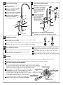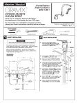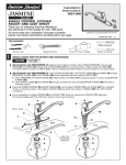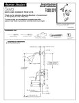
1
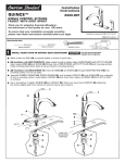
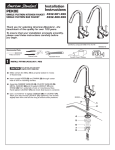
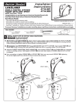
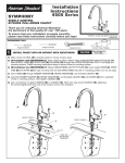
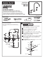
Installation
Instructions
3821.831
3821.834
HI-FLOW
KITCHEN FAUCET
Thank you for selecting American-Standard...
the benchmark of fine quality for over 100 years.
To ensure that your installation proceeds smoothly-please read these instructions carefully before you begin.
Certified to comply with ANSI A112.18.1M
M968150 REV. 1.1
TOOLS REQUIRED
Phillips Screwdriver
Channel Locks
Adjustable Wrench
1
ROUGHING-IN DIMENSIONS
Before starting installation, place each component loosely
into the holes of the kitchen sink to select the most desirable
arrangement.
Regular Screwdriver
Plumbers' Putty or Caulking
VALVE INSTALLATION
CAUTION
Turn off water at
main supply.
This faucet permits an interchangeable mounting of each integral
component -- spout, valve, and hand spray -- to suit the particular
installation requirements.
Remove LOCKNUT (1) and RETAINER PLATE (2).
Insert SUPPLY TUBES (3), SPOUT HOSE (4) and
THREADED STUD (5) through hole in SINK.
Make sure O-RING (6) is properly seated in recess of BASE.
9-3/8
10" MAX
8-5/8
13
10 MAX
VALVE
1-1/4
MIN. DIA
MTG HOLE
2 DIA.
2 DIA.
1-1/4 MAX
27/32
DIA.
SPRAY
HOSE
1-1/16
MAX
MTG
SURFACE
1-1 /4 MAX
Orient VALVE (7) so that two inlets tubes face towards the front.
Assemble RETAINER PLATE (2) and LOCKNUT (1) onto
STUD (5) from underside of SINK.
Hand tighten LOCKNUT (1) and check that rotation of HANDLE
from HOT to COLD is centered. Secure VALVE (7) position by
tightening LOCKNUT (1) firmly. (Spread TUBES for better
access to LOCKNUT).
Bend TUBES (3) to meet supplies. Use palm of hand to support
TUBES (3) while bending to avoid kinking.
2-1/2
DIA.
7-1/8
13/16
DIA
7
C/L OF
FLEXIBLE HOSE
TO SPOUT
HOT
6
5
COLD
4
SINK
3
3/8 OD COPPER
BENDABLE
2
SPOUT HOSE
1
SPRAY HOSE
2
3
SPOUT INSTALLATION
Insert SPOUT SHANK (1)
through sink hole.
Note: For installation less spray, cap off
THREADED STUD with PIPE CAP.
Place SPRAY HOLDER (1)
into separate hole of SINK
and assemble WING NUT
(2) onto SHANK from
underside of SINK and
tighten.
Make sure RUBBER RING (2)
is properly seated in recess
of ESCUTCHEON (3).
Center SPOUT ESCUTCHEON (3)
and tighten WING NUT(4) firmly.
Connect SPOUT HOSE (5)
to SPOUT SHANK (1). (SPOUT
HOSE is connected to
1
VALVE BODY already).
HAND SPRAY INSTALLATION
7
1
Feed SPRAY HOSE (3)
through HOLDER (1)
and attach COUPLING
(4) to THREADED
STUD of VALVE.
Tighten COUPLING
NUT (4) firmly.
3
2
6
5
8
2
3
4
4
5
Make certain that SPACER WASHER (5) and
RUBBER WASHER (6) are attached to SPRAY
HOSE (3) and thread SPRAY HEAD (7) to NUT (8).
SPRAY HOSE
4
CONNECT SUPPLIES
Bend TUBES to meet supplies. Use palm of hand to support TUBES
while bending to avoid kinking.
OR
Connect 3/8-inch OD inlet TUBES to water supplies with appropriate connectors.
Connect LEFT tube to HOT water supply and RIGHT tube to COLD.
TEST INSTALLED FAUCET
Move handle down into "off" position, remove AERATOR.
With HANDLE in "off" position, turn on water supplies
and check all connections for leaks.
Move handle down into "off" position and replace AERATOR.
SERVICE
AERATOR may accumulate dirt causing distorted and reduced water flow. Remove AERATOR and rinse clean.
If SPOUT drips, operate handles several times from OFF to ON position. Do not force - handle.
HOT LIMIT SAFETY STOP ADJUSTMENT
By restricting handle rotation and limiting the amount of hot water allowed
to mix with the cold, the HOT LIMIT SAFETY STOP reduces risk of accidental
scalding. To set the maximum hot water temperature of your faucets, all you
need to do is adjust the setting on the HOT LIMIT SAFETY STOP.
"A"
PRY RED RING FORWARD
AND ROTATE COUNTERCLOCKWISE ONE CLICK
"A"
TEMPERATURE
3
4
"A"
ADJUSTMENT WHEN
WATER IS TOO HOT
5
6
6
Replace ESCUTCHEON CAP (4), HANDLE (3), tighten
HANDLE SCREW (1) and install INDEX BUTTON (2).
2
Remove HANDLE BUTTON (1) and loosen SET SCREW (2). Pull
SETTING NUMBERS
HANDLE (3) off valve stem. Pull off CAP (4). Use a flat blade
"B"
screwdriver or your fingers to pull up and rotate red
PRY RED RING FORWARD
HOT LIMIT SAFETY STOP (5). Follow Step "A" or "B" to adjust AND ROTATE CLOCKWISE
min./max.discharge temperature. "0" being the hottest to
"B"
"B"
"7" the coldest temperature setting. Factory set at "0".
1
6
Operate handle up and down, in COLD and HOT positions,
to flush water lines thoroughly and check spout mounting
for leaks.
Direct SPRAY HEAD into sink. Open faucet and activate
spray. Check SPRAY HOSE connections for leaks.
0
5
ADJUSTMENT WHEN
WATER IS TOO COLD
5
"RED RING"- HOT
LIMIT SAFETY STOP
M968150 REV. 1.1