1
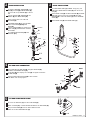
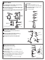
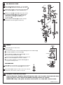
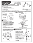
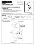
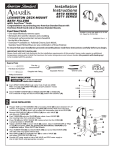
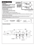
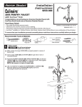
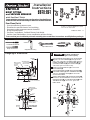
Installation
Instructions
ENFIELD
2373.401
2373.421
BIDET FITTING
and VACUUM BREAKER
with EverClean™ Finish
Congratulations on purchasing your American Standard faucet
with EverClean finish found only on American Standard faucets.
EverClean Finish
• One wipe effortlessly removes spots
Certified to comply with ASME A112.18.1M
• Eliminates the need for cleaners and scrubbing
U.S. Patent No. 5,819,789
• Permanent surface protectant remains beautiful
.3&7
for the life of the faucet
• EverClean™ available on: Polished Chrome, Satin Nickel,
Stainless Steel, Polished Brass (or any combination of these finishes)
To ensure that your installation proceeds smoothly-please read these instructions carefully before you begin.
Required Tools
*Wrench
Flat Blade Screwdriver
Adjustable Wrench
Phillips Screwdriver
5VCJOH$VUUFS
*Supplied with Fitting
Roughing-in Dimensions
FINISHED
WALL
BIDET OUTLINE
IS SYMBOLIC
DOUCHE
SPRAY
Channel Locks
TRANSFER VALVE
(FOR FLUSHING
RIM OR SPRAY)
7/8 DIA.
ADJ. 1-1/4
TO 2-1/4
CAUTION
Turn off hot and cold water
supplies before beginning.
Place MOUNTING NUTS (1) onto the VALVE BODIES
(2) and insert VALVE BODIES (2) through outside
holes, from underside of the BIDET LEDGE. Drop the
RUBBER RING (3) over the VALVE BODIES (2) and
thread DECK ADAPTER (4) onto VALVE BODIE (2)
until it locks against the internal stop.
Tighten the MOUNTING NUT (1) to secure the
VALVE BODIES (2).
2-1/8
DIA.
Remove MOUNTING NUT (9), FRICTION RING (10)
and UPPER GASKET (7) from TRANSFER VALVE (8)
and insert TRANSFER VALVE (8) into the center
forward hole of BIDET.
1-3/8
DIA.
3-7/8
MOUNTING BIDET FAUCET
5-1/2
1-1/4 O.D. TAILPIECE
Replace UPPER GASKET (7) and FRICTION RING (10).
Position the side threaded outlet rearward and secure
MOUNTING NUT (9). Thread ESCUTCHEON (5) onto
TRANSFER VALVE (8) until it seats against the
BIDET LEDGE.
9
5
8 TO 12
(C)
DIVERTER AND
VACUUM BREAKER
ASSEMBLY
10
4
(H)
2-1/4
DIA.
1-3/16
DIA.
1-1/4
MAX.
FINISHED
FLOOR
4-1/4
3
BIDET
LEDGE
FOR GROUND JOINT
CONNECTION OR 1/2"
O.D. SLIP (INLETS)
REAR VIEW WITH
WALL REMOVED
2
COLD
HOT
1
7
8
DRAIN INSTALLATION
SPRAY INSTALLATION
Assemble SPRAY BODY (1) to BIDET. Using putty, seal
underside of SPRAY BODY FLANGE (2) and secure with
NUT (3).
Assemble O-RING (1), WASHER (2), PIVOT
ROD (3) and NUT (4) to DRAIN BODY (5).
Concave side of cup WASHER (2) is toward
ball.
Thread LOCKNUT (6), WASHER (7) and
GASKET (8) onto DRAIN BODY (5).
Screw SPRAY HOSE (4) with SEAL WASHER (5) to SPRAY
BODY (1). Connect other end of HOSE (4) with SEAL
WASHER (6) to side outlet NIPPLE (7) of the TRANSFER
VALVE (8).
Apply a bead of PUTTY to underside
of FLANGE (9).
Screw SPRAY CAP (9) onto SPRAY BODY (1).
Feed DRAIN BODY (5) up through BIDET
and thread FLANGE (9) fully onto
BODY (5).
Tighten LOCKNUT (6) firmly, keeping the
PIVOT ROD (3) pointed towards the back
of the BIDET.
Push DRAIN ESCUTCHEON (10) onto
TAILPIECE (11).
STOPPER
9
PUTTY
8
BIDET
8
7
CLIP
9
2
7
1
PUTTY
4
2
6
3
6
3
1
5
5
4
11
10
TEE AND HOSE CONNECTION
Cold
Insert SEAL (1) into ADAPTER (2) and tighten ADAPTER (2)
to bottom of TRANSFER VALVE (3).
3
Install SEAL (4) into coupling nut of TEE (5) and tighten connection
to ADAPTER (2)
1
2
Connect HOSE COUPLING NUTS (6) to Hot and Cold
valve bodies and securely tighten.
4
6
COUPLING
NUT
Hot
6
5
Front
LIFT ROD GUIDE INSTALLATION
Unscrew LIFT ROD NUT (1) from LIFT ROD GUIDE (2).
Make sure SEAL (3) is seated into ESCUTCHEON of LIFT ROD GUIDE (2).
2
3
Drop LIFT ROD GUIDE (2) into rear hole of bidet and from
below secure with ROD GUIDE NUT (1).
1
.3&7
INSTALL HANDLES
DIVERTER KNOB:
Push ADAPTER (1) on VALVE STEM (2), so that the hole of the
ADAPTER (1) without a spline is facing up. See figure "A". Tighten
STEM SCREW (3) to secure ADAPTER (1).
Install HANDLE ADAPTER (8) onto valve stem.
Find correct position of LEVER HANDLE ASSEMBLY (4) or CROSS
HANDE ASSEMBLY (5) by adjusting male teeth on ADAPTER (1) to
female teeth in HANDLE (4, 5).
Install RING (9) onto DIVERTER KNOB (7) and tighten
with HANDLE SCREW (10).
Thread LEVER HANDLE ASSEMBLY (4) or CROSS HANDE ASSEMBLY
(5) onto DECK ADAPTER (6) until snug against mounting surface.
Push DIVERTER KNOB (7) onto HANDLE ADAPTER (8).
Press on KNOB CAP (11).
11
10
4
5
9
THREAD ON
TO DECK
ADAPTER
7
8
TOP
VALVE STEM
1
Figure "A"
3
2
SPLINE END DOWN
6
WATER SUPPLY CONNECTIONS
NOTE: FLEXIBLE SUPPLIES ARE NOT INCLUDED AND HAVE TO BE
PURCHASED SEPARATELY.
1
Connect water supplies to FAUCET (1) with 1/2" IPS
FLEXIBLE SUPPLIES (2) or 3/8" O.D. BULL-NOSE RISERS (3).
Use adjustable wrench to tighten connections.
2
COUPLING NUT
Do not over tighten. Be careful not to kink copper supply
when bending. Use tubing cutter to cut to proper length.
3
Cold
Hot
FINISH DRAIN INSTALLATION
FERRULE
2
1
Position BIDET fixture and secure to floor.
3
Insert lift rod into lift rod guide.
Position EXTENSION ROD (1) onto POP-UP ROD (2) and tighten
THUMBSCREW (3).
7
1
Remove one end of CLIP (4) from PIVOT ROD (7) by squeezing ends
together while sliding.
Insert PIVOT ROD (7) into second or third hole in EXTENSION ROD (1)
and reassemble CLIP (4). (EXTENSION ROD (1) may need to be bent.)
5
4
Adjust STOPPER height by repositioning EXTENSION ROD (1) and
tightening THUMBSCREW (3).
Using metal TAILPIECE (5), make connection to the TRAP (6).
6
.3&7
TEST INSTALLED FITTING
1
With HANDLES (1) in OFF position, turn on WATER
SUPPLIES (2) and check all connections for leaks.
6
Operate both handles to flush water lines thoroughly.
Turn DIVERTER (6) to rim wash and bidet spray.
3
Operate Lift Rod (3) and fill Bidet with water. Check
that DRAIN STOPPER (4) makes a good seal and
retains water in Bidet. Adjust stopper height by
repositioning Lift Rod (3) and tightening
Thumbscrew (5).
Release DRAIN STOPPER (4) and check all drain
connections for leaks.Tighten if necessary.
5
2
4
2
SERVICE
HANDLE
ASSEMBLY
To change direction of handle rotation,
proceed as follows:
Turn valve to OFF position. Unthread HANDLE BASE (1) from DECK ADAPTER (2).
Pull HANDLE ASSEMBLY off VALVE STEM (3).
UNTHREAD
Remove SPRING CLIP (4). Lift STOP WASHER (5), turn 90p
and replace. Replace SPRING CLIP (4).
1
Find correct position of HANDLE ASSEMBLY by adjusting male
teeth on VALVE STEM (3) to female teeth in HANDLE.
Thread HANDLE ASSEMBLY onto DECK ADAPTER (2) until
snug against mounting surface.
TO CLEAN SPRAY
SPRAY (6) may accumulate dirt causing distorted and reduced
water flow. Unscrew and remove SPRAY (6) and rinse clean.
90p
3
5
6
4
2
Replace SPRAY (6) and operate handles several times from OFF
to ON position. Do not force, handles turn only 90˚.
EverClean™ Finish Care Instructions
American Standard’s EverClean finish will wipe clean with a soft, dry cloth. A soft cloth with clean
water may also be used, if desired. No additional cleaning products are required.
DO NOT USE: Soaps, acid, polish, abrasives, harsh cleaners, or a cloth with a coarse surface.
.3&7