1
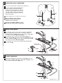
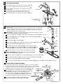
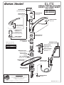
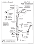
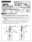
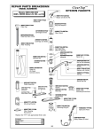
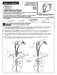
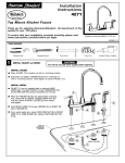
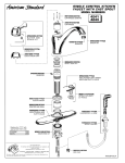
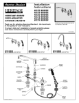
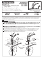
Installation
Instructions
ELITE
4453 SERIES
4454 SERIES
SINGLE CONTROL KITCHEN FAUCET
and HAND SPRAY
Thank you for selecting American-Standard...
the benchmark of fine quality for over 100 years.
To ensure that your installation proceeds smoothly-please read these instructions carefully before you begin.
Certified to comply with ANSI A112.18.1M
M968202 REV.1.2
TOOLS REQUIRED
Phillips Screwdriver
Channel Locks
Adjustable Wrench
Regular Screwdriver
Plumbers' Putty or Caulking
CARE:
DO: SIMPLY RINSE THE PRODUCT CLEAN WITH CLEAR WATER. DRY WITH A SOFT COTTON FLANNEL CLOTH.
DO NOT: DO NOT CLEAN THE PRODUCT WITH SOAPS, ACID, POLISH, ABRASIVES, HARSH CLEANERS, OR A
CLOTH WITH A COARSE SURFACE.
1
INSTALL FAUCET WITH OR WITHOUT DECK ESCUTCHEON
CAUTION
Turn off hot and cold water
supplies before beginning.
(A) Installation with ESCUTCHEON (1). Apply a bead of putty to bottom edge of ESCUTCHEON WITH PUTTY PLATE (1).
Insert supply HOSES (3) and SHANK (4) through hole of ESCUTCHEON WITH PUTTY PLATE (1) and mounting surface.
Make certain the SQUARE SEAL RING (2) is properly seated in recess of SPOUT BASE. Follow mounting instructions below
to secure faucet to mounting surface.
(B) Installation less ESCUTCHEON (1). Remove ESCUTCHEON WITH PUTTY PLATE (1) and Insert supply HOSES (3) and
SHANK (4) through mounting hole and seat SPOUT BASE onto sink or mounting surface. Make certain the SQUARE SEAL
RING (2) is properly seated in recess of SPOUT BASE. Do not use putty.
Assemble RUBBER WASHER (5), BRASS WASHER (6), and threaded LOCKNUT (7) onto SHANK (4) from underside
of sink or mounting surface. Hand tighten LOCKNUT (7) and check that rotation of HANDLE (8) from HOT to COLD
is centered.
Use a screwdriver to tighten SCREWS (9) on LOCKNUT (7). Work your way around LOCKNUT (7), tightening
the screws slightly each time until all are snug to ensure even pressure.
8
B
A
8
SPOUT BASE
SPOUT BASE
SQUARE
SEAL RING
2
1
SQUARE
SEAL RING
2
4
3
PUTTY
3
4
5
SINK OR
MOUNTING
S U R FA C E
5
6
6
9
7
9
7
2
MAKE WATER SUPPLY CONNECTIONS
Turn off hot and cold water supplies before beginning.
Connect FLEXIBLE SUPPLIES (1, 2) directly
to wall supplies. Connection on fitting
supplies are 3/8" compression. Connect
left supply to Hot (Marked with a Red Tag)
and right supply to Cold wall supply. Use
adjustable wrench to tighten connections.
Do not over tighten.
2
1
Faucet supplies are 21" long from faucet base.
Note: If additional supply length is
required, installer must purchase
additional parts separately.
COLD
HOT
Important: If SUPPLY HOSES (1, 2) are
too long, loop as illustrated to avoid kinking.
3
INSTALL SPRAY HOLDER
On model with separate spray, place the SPRAY HOLDER (1)
into the appropriate mounting hole. Assemble the SPRAY
HOLDER WING NUT (2) onto the shank of SPRAY HOLDER (1)
from below and tighten. Do not use putty.
On model with spray through the ESCUTCHEON (3), place
SPRAY HOLDER (4) into the hole of ESCUTCHEON (3). Assemble
SPRAY HOLDER NUT (5) onto the shank of SPRAY HOLDER (4)
from below and tighten. Do not use putty.
1
For installation less spray cap off SPRAY HOSE CONNECTION
with PIPE CAP (6).
SPRAY HOSE
CONNECTION
3
4
5
4
2
6
CONNECT HOSE SPRAY
Feed SPRAY HOSE (1) through SPRAY HOLDER (2) and attach
COUPLING NUT (3) of HOSE (1) to HOSE ADAPTOR (4) on valve
body. Tighten COUPLING NUT (3) firmly.
1
2
4
3
M968202 REV.1.2
5
TEST INSTALLED FAUCET
Move HANDLE down into "off" position and remove AERATOR.
Turn on water supplies and check connections for leaks.
Operate HANDLE up and down, left and right to flush water
lines thoroughly.
For faucet with spray, direct SPRAY HEAD into sink and
activate SPRAY. Check hose connections for leaks.
Move HANDLE down to "off" position and replace AERATOR.
A E R AT O R
CHECK CONNECTIONS
FOR LEAKS
SERVICE
Reduced flow. If the flow gradually reduces over a number of months, the AERATOR
may have collected debris. To clean, remove AERATOR and rinse with water and
remove any debris. Turn on faucet to wash any debris out of the faucet. Thread
AERATOR back into spout. Operate faucet.
Spout leakage. If fitting leaks above or below SPOUT HUB remove SPOUT as follows
and check SPOUT O-RINGS and SPACER O-RINGS.
1
3
2
4
5
Remove HANDLE BUTTON (2) and loosen SET SCREW (1). Pull HANDLE (3) off valve stem.
6
Remove CAP (4) and and RETAINER (5). Loosen CARTRIDGE SCREWS (6) and
remove CARTRIDGE (7).
7
12
Pull off SPACER (8) and O-RINGS (9).
8
Remove SPOUT (12) by pulling up gently while moving SPOUT (12) side to side.
Check both SPOUT O-RINGS (11). Replace if necessary.
9
A E R AT O R
SPOUT
HUB
On models with SPRAYS, DIVERTER (10) can be cleaned by pulling
DIVERTER (10) out of the MANIFOLD (13). Clean DIVERTER (10) and
MANIFOLD (13). Push DIVERTER (10) back into MANIFOLD (10).
11
Reverse procedure to reinstall SPOUT, CARTRIDGE and HANDLE.
10
Clogged CARTRIDGE outlets or inlets may cause reduced flow.
To clean, first turn off water supply then:
13
Remove PLUG BUTTON (2), loosen HANDLE SCREW (1) and remove HANDLE (3).
Remove ESCUTCHEON CAP (4). unscrew the three CARTRIDGE SCREWS (6).
Clean inlets of CARTRIDGE (7) and MANIFOLD (13).
Reassemble CARTRIDGE (7), alternately tightening SCREWS (6). Replace CAP (4) and HANDLE (3). Check flow.
HOT LIMIT SAFETY STOP ADJUSTMENT
By restricting handle rotation and limiting the amount of hot water allowed
to mix with the cold, the HOT LIMIT SAFETY STOP reduces risk of accidental
scalding. To set the maximum hot water temperature of your faucets, all you
need to do is adjust the setting on the HOT LIMIT SAFETY STOP.
"A"
PRY RED RING FORWARD
AND ROTATE COUNTERCLOCKWISE ONE CLICK
"A"
TEMPERATURE
1
3
4
"A"
ADJUSTMENT WHEN
WATER IS TOO HOT
5
6
Replace ESCUTCHEON CAP (4), HANDLE (3), tighten
HANDLE SCREW (1) and install INDEX BUTTON (2).
2
Remove HANDLE BUTTON (1) and loosen SET SCREW (2). Pull
SETTING NUMBERS
HANDLE (3) off valve stem. Pull off CAP (4). Use a flat blade
"B"
screwdriver or your fingers to pull up and rotate red
PRY RED RING FORWARD
AND ROTATE CLOCKWISE
HOT LIMIT SAFETY STOP (5). Follow Step "A" or "B" to adjust
min./max.discharge temperature. "0" being the hottest to
"B"
"B"
"7" the coldest temperature setting. Factory set at "0".
0
6
6
ADJUSTMENT WHEN
WATER IS TOO COLD
5
"RED RING"- HOT
LIMIT SAFETY STOP
M968202 REV.1.2
ELITE
SINGLE CONTROL KITCHEN
FAUCET with HAND SPRAY
MODEL NUMBERS
023603-0070A
CARTRIDGE SCREWS
060343-0070A
S PA C E R W I T H
O-RINGS
023529-0070A
CARTRIDGE
4453 SERIES
4454 SERIES
060474-YYYOA
SPOUT KIT
030126-0070A
BUTTON AND
SCREW KIT
066070-YYY0A
AERATOR
060342-YYY0A
HANDLE KIT
907468-YYY0A
ESCUTCHEON CAP
921877-0070A
CAP RETAINER
Replace the "YYY" with
appropriate finish code
CHROME
POLISHED BRASS
WHITE HEAT
SATIN NICKEL
060366-0070A
SPOUT SEAL KIT
042850-0070A
DIVERTER
002
099
208
295
M953667-YYY0A
HAND SPRAY & HOSE
060484-YYY0A
ESCUTCHEON WITH
SPRAY HOLE
M909320-YYY0A
SPOUT FLANGE
M961773-YYY0A
S P R AY H O L D E R
(3-HOLE)
923310-0070A
SPACER
A911758-0070A
SQUARE SEAL RING
060485-YYY0A
ESCUTCHEON
030760-YYY0A
SPRAY HOLDER
M962146-0070A
MOUNTING KIT
HOT LINE FOR HELP
For toll-free information and answers to your questions, call:
1-800-442-1902
Weekdays 8:00 a.m. to 6:00 p.m. EST
IN CANADA 1-800-387-0369 (TORONTO 1-905-306-1093)
Weekdays 8:00 a.m. to 7:00 p.m. EST
IN MEXICO 01-800-839-12-00
Product names listed herein are trademarks of American Standard Inc.
© AS America, Inc. 2008
060341-0070A
PIPE CAP
M968202 REV.1.2