1
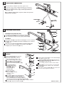
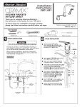
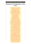
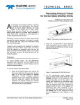
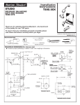
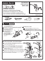
Installation
Instructions
2021.6XX
TM
KITCHEN FAUCETS
Thank you for selecting American-Standard...
the benchmark of fine quality for over 100 years.
To ensure that your installation proceeds smoothly-please read these instructions carefully before you begin.
Certified to comply with ASME A112.18.1M
M 6 6 2 4 0 R E V. 1 . 1
TOOLS REQUIRED
Channel Locks
1
CAUTION
Adjustable Wrench
Phillips Screwdriver
Plumbers' Putty or Caulking
Turn off water at
main supply.
Install ESCUTCHEON (optional)
FOR MODEL 2021.631 ONLY:
Peel off paper backing from WASHER (1, 1a) and stick WASHER
(1, 1a) into circular groove of the SUPPORT PLATE (2, 2a).
Install ESCUTCHEON (3a) (as described on the left).
Place SUPPORT PLATE (2, 2a) in
Insert SPRAY HOLDER (5) through side hole of installed
center of ESCUTCHEON (3, 3a)
ESCUTCHEON (3a), thread WING NUT (6) to shank of SPRAY
with WASHER (1) visible.
HOLDER (5) from underside of sink. Center SPRAY HOLDER (5)
2
1
Turn ESCUTCHEON (3, 3a) over
on ESCUTCHEON (3a) and secure by tightening WINGNUT (6).
with notch of SUPPORT
INSTALL
PLATE (2, 2a) towards rear of
5
sink, align STUDS (4) with
4
outer holes of sink and
INSTALL
place ESCUTCHEON (3, 3a) onto
3a
2a
deck. Hole of SUPPORT
PLATE (2, 2a) must align with
hole of sink.
GE
ED
4
AR
RE
3
2
AR
6
RE
FAUCET INSTALLATION (ESCUTCHEON OPTIONAL)
Make sure black RUBBER GASKET (4) is properly centered on base.
Orient faucet so that threaded STUD (2) is centrally located towards
rear of sink, then assemble RETAINER PLATE with GASKET (5), or
MOUNTING KIT (5a) and thread LOCKNUT (6, 6a) onto MOUNTING
STUD (2) from underside of sink.
3
Hand tighten LOCKNUT (6, 6a) and check that rotation of HANDLE (7)
from HOT to COLD is centered. Secure faucet by tightening LOCKNUT
(6, 6a) firmly. Spread TUBES (1) for better access to LOCKNUT (6, 6a).
If using ESCUTCHEON (3), thread ESCUTCHEON WING NUTS (8) onto
studs from underside of sink and hand-tighten.
3a
LESS ESCUTCHEON
7
Insert supply TUBES (1) and threaded MOUNTING STUD (2)
through center hole of ESCUTCHEON (3) and sink deck, or selected
sink hole if ESCUTCHEON (3) is not used.
GE
ED
8
4
4
1
2
1
5
5
6
6
LOCKNUT
(FAUCETS
LESS SPRAY)
6a
LOCKNUT
5a
MOUNTING KIT
FOR FTG. WITH
HAND SPRAY
6a
3
WATER SUPPLY CONNECTIONS
Bend 3/8” SUPPLY TUBES to meet water supplies valves.
Use palm of hand to support TUBES while bending to avoid kinking.
Connect inlet TUBES to water supplies with appropriate connectors.
Connect left TUBE to HOT water supply, and the right TUBE to the
COLD water supply.
Note: If additional supply length is required, installer must purchase
additional parts separately.
COMPRESSION
NUT
3/8 O.D.
SUPPLIES
FERRULE
HOT
COLD
4
HAND SPRAY INSTALLATION
9
7
6
FOR MODELS WITH HAND SPRAY ONLY:
Place SPRAY HOLDER (1) into the appropriate mounting hole,
assemble WING NUT (2) onto shank of SPRAY HOLDER (1)
from underside of sink and secure by tighting WING NUT (2).
8
ALL MODELS:
Feed SPRAY HOSE (5) through SPRAY HOLDER (1) and attach COUPLING
NUT (4) of SPRAY HOSE (5) to MOUNTING STUD (3). Tighten COUPLING
NUT (4) firmly.
Make certain that SPACER WASHER (6) and RUBBER WASHER (7)
are attached to SPRAY HOSE (5) and thread SPRAY HEAD (9) to
NUT (8). Tighten COUPLING NUT (8) firmly.
1
3
4
5
2
5
SERVICE
3
Clogged CARTRIDGE (1) inlets or outlets
may cause reduced flow in "full on,"
hot or cold. To clean ports, first turn
off Hot and Cold water supplies, then:
2
Remove BUTTON (2), loosen HANDLE
SCREW (3) and pull HANDLE (4) off.
Remove ESCUTCHEON CAP (5).
Remove three MOUNTING SCREWS (6).
Lift CARTRIDGE (1) off
MANIFOLD (7), remove
SEALS (8). Clean ports,
SEALS (8), FLOW
REGULATOR (9) and
MANIFOLD (7).
If hand spray water
flow is restricted, lift
DIVERTER (10) using longnose pliers. Clean
and replace.
10
4
5
6
1
9
8
Slip SPOUT (12) off MANIFOLD (7) and replace LIP
SEALS (11) and BEARING RING (13). Make certain
SEALS (11) are well lubricated.
For assembly, proceed as above in reverse order.
AERATOR (14) may accumulate dirt causing distorted
and reduced water flow. Remove, clean, and replace
AERATOR (14).
If faucet drips, operate HANDLE (4) several times from
"off" to "on." Do not apply excessive force.
14
Insert SEALS (8) back into CARTRIDGE (1). 11
Make certain larger diameter of FLOW
REGULATOR (9) faces inside CARTRIDGE (1).
Place CARTRIDGE (1) onto MANIFOLD (7) and
alternately tighten the three MOUNTING SCREWS (6).
Replace ESCUTCHEON CAP (5), HANDLE (4), and tighten HANDLE
SCREW (3). Replace PLUG BUTTON (2).
To replace SPOUT SEALS (11), remove CARTRIDGE (1)
as described on the left, then:
12
13
7
M 6 6 2 4 0 R E V. 1 . 1
6
TEST INSTALLED FITTING
With HANDLE (1) in OFF position, turn on
WATER SUPPLIES (2) and check all
connections for leaks.
1
Remove AERATOR (3).
Operate HANDLE (2) up and down, in COLD and HOT
positions, to flush water lines thoroughly.
Direct SPRAY HEAD (3) into sink. Open faucet and
activate spray. Check SPRAY HOSE (4) connections
for leaks.
3
Replace AERATOR (3).
2
7
ADJUST HOT LIMIT STOP
By restricting handle rotation and limiting the amount of hot water allowed to mix with the cold, the HOT LIMIT
SAFETY STOP reduces risk of accidental scalding. To set the maximum hot water temperature of your faucet,
all you need to do is adjust the setting on the HOT LIMIT SAFETY STOP (1).
Use a flat blade screwdriver or your fingers to pull up and rotate red HOT LIMIT SAFETY STOP (1). Follow Step "A" or
"B" to adjust min./max. discharge temperature. "0" being the hottest to "7" the coldest temperature setting. Factory
set at "0".
"A"
PRY RED RING FORWARD
AND ROTATE COUNTERCLOCKWISE ONE CLICK
"A"
1
2
3
"A"
ADJUSTMENT WHEN
WATER IS TOO HOT
5
6
"B"
4
"B"
PRY RED RING FORWARD
AND ROTATE CLOCKWISE
0
TEMPERATURE
SETTING NUMBERS
"B"
1
ADJUSTMENT WHEN
WATER IS TOO COLD
"RED RING"- HOT
LIMIT SAFETY STOP
8
CARE INSTRUCTIONS:
DO: SIMPLY RINSE THE PRODUCT CLEAN WITH CLEAR WATER. DRY WITH A SOFT COTTON FLANNEL
CLOTH.
DO NOT: DO NOT CLEAN THE PRODUCT WITH SOAPS, ACID, POLISH, ABRASIVES, HARSH CLEANERS,
OR A CLOTH WITH A COARSE SURFACE.
M 6 6 2 4 0 R E V. 1 . 1