1
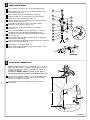
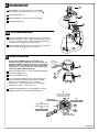
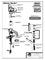
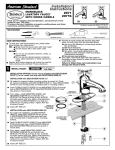
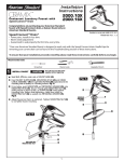
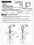
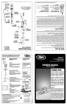
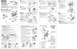
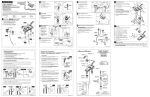
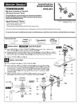
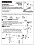
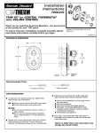
Installation
Instructions
THE
COLLECTION
by
™
MONOBLOCK
LAVATORY FAUCET
SINGLE LEVER
2171
Thank you for selecting American-Standard...the benchmark of fine
quality for over 100 years.
To ensure that your installation proceeds smoothly--please read these
instructions carefully before you begin.
Certified to comply with ANSI A112.18.1M
M968291C
TOOLS REQUIRED
Channel Locks
Adjustable Wrench
CARE INSTRUCTIONS:
To keep your new faucet looking new, please follow
these simple care instructions:
DO:
Simply rinse the faucet clean with clear water.
Dry the faucet with a soft cotton cloth.
INSTALL FAUCET
CAUTION
Phillips Screwdriver
Remove as much surface dirt and film using clear
water and soft cotton cloth (as described above).
Use any of the following to remove tough surface
film and build-up:
Mild liquid detergents
Clear ammonia free liquid glass cleaners
Non-acidic, non-abrasive gentle liquid or fully
dissolved powder cleansers mixed according to
manufacturers directions.
Non-abrasive liquid polishers
Once clean, rinse faucet again with clear water to
thoroughly remove cleaner or polish and blot dry with
a soft cotton cloth.
Failure to follow these care instructions may
damage the Faucet's finish.
DO NOT:
Do not use any abrasive cleaners, cloths, or
paper towels.
Do not use any cleaning agents containing
acids, polish abrasives, or harsh cleaners or
soaps.
Regular and routine cleaning will reduce the need for
heavy cleaning and polishing. If heavy cleaning is
required, the following procedures are recommended:
1
Plumbers' Putty or Caulking
Turn off water at
main supply.
INSTALLATION OPTIONS; Faucet may be installed with ESCUTCHEON
PLATE (1) or for center hole only with ESCUTCHEON RING (2).
7
INSTALLATION with ESCUTCHEON PLATE (1)
No sealant is required unless mounting surface is uneven for 3-hole (4" centers)
installation with ESCUTCHEON PLATE (1). Place ESCUTCHEON PLATE (1) over
mounting holes on lavatory sink or mounting surface.
Feed FLEXIBLE FAUCET HOSES (3) and MOUNTING STUD (4) through
hole in ESCUTCHEON PLATE (1). Seat ESCUTCHEON PLATE (1) boss
into groove in Faucet base.
From below, install MOUNTING GASKET with
RETAINING WASHER (5) and Nut (6) onto
STUD (4). Pull Faucet to front of sink, so STUD BOSS
(4) rests against sink hole. Before final tightening,
align Faucet and ESCUTCHEON (1) so they are
centered on mounting surface. Tighten NUT (6)
to secure Faucet
GROOVE IN
Insert LIFT ROD (7).
BOSS
1
4
2
ESCUTCHEON
RING BASE
INSTALLATION with ESCUTCHEON RING (2)
For single hole installation use ESCUTCHEON
RING (2). Install SEAL WASHER (6) into groove
in ESCUTCHEON RING (2) base and place over
over mounting hole in lavatory sink or mounting
surface.
Feed FLEXIBLE FAUCET HOSES (3) and MOUNTING
STUD (4) through hole in ESCUTCHEON RING (2).
Seat ESCUTCHEON RING (2) boss into groove in
Faucet base.
From below, install MOUNTING GASKET with
RETAINING WASHER (5) and Nut (6) onto
STUD (4). Pull Faucet to front of sink, so STUD
(4) rests against sink hole. Before final tightening,
align Faucet and ESCUTCHEON (1) so they are
centered on mounting surface. Tighten NUT (6)
to secure Faucet
Insert LIFT ROD (7).
GROOVE IN
FAUCET BASE
6
LAVATORY SINK
OR MOUNTING
SURFACE
3
5
6
2
INSTALL POP-UP DRAIN
Push Tail piece (11) down into Trap (C) (threaded end up).
Thread Locknut (5), Washer (4) and Gasket (3) (Bevel side
up) onto Drain Body (10).
Apply a bead of Putty (D) to underside of Flange (2).
Feed Drain Body (10) up through Sink (A) and thread the
Flange (2) or (2A) fully onto Drain Body (10).
Tighten Locknut (5) firmly, keeping the pivot rod hole pointed
towards the back of the sink.
Assemble Pivot Rod (9) as shown in Figure-3A. Notice
the position of the Concave Washer (G).
1
2
D
A
E
3
6
Insert Pivot Rod (9) into Drain Body (10) and tighten
Pivot Nut (F).
4
7
Push TAILPIECE INSERT (12) into TAILPIECE (11) and push
TAILPIECE up and thread tightly into DRAIN BODY (10).
Position Extension Rod (7) onto Pop-Up Rod (E) and tighten
Thumbscrew (6).
Remove one end of Clip (8) from Pivot Rod (9) by squeezing
ends together while sliding.
Insert Pivot Rod (9) or (9A) into second or third hole in Extension
Rod (7) and reassemble Clip (8).
5
7
8
F
10
12
9
C
11
1-1/4"
Drop Stopper (1) into Drain Body (10).
Adjust stopper height by repositioning Extension Rod (7) and
tightening Thumbscrew (6).
9
F
G
O-RING
FIGURE-3A:
3
WATER SUPPLY CONNECTIONS
Note: FLEXIBLE HOSES (1, 2) on FAUCET (3) are (17-1/2") in
length from base of faucet. If longer supply length is required
installer must purchase adapters and additional supplies to
complete connections.
Important: If SUPPLY HOSES (1, 2) are to long, loop as
illustrated to avoid kinking . (Do not cut Flexible Hoses 1, 2)
3
Connection on FLEXIBLE HOSES (1, 2) are 3/8" compression.
Connect LEFT SUPPLY (1) to Hot shut off valve and RIGHT
SUPPLY (2) to Cold shut off valve.
Use adjustable wrenches to tighten connections. Do not
over tighten.
(17-1/2")
1
COLD
2
3/8" compression
HOT
SHUT OFF
VALVE
M968291C
4
TEST INSTALLED FAUCET
AND CHECK FOR LEAKS
1
With HANDLE (1) in OFF position, turn on WATER
SUPPLIES (2) and check all connections for leaks.
Remove AERATOR (3).
3
Operate HANDLE (1) to flush water lines thoroughly.
4
Replace AERATOR (3).
6
5
4a
CHECK DRAIN CONNECTIONS
Operate LIFT ROD (4) and fill lavatory with water. Check that
DRAIN STOPPER (5) makes a good seal and retains water in
lavatory. If necessary adjust stopper height by repositioning
LIFT ROD (4) and tightening Thumbscrew (6).
"P" TRAP
Release DRAIN STOPPER (5) and check all drain connections
and "P" trap for leaks. Tighten if necessary.
COLD
2
HOT
ADJUST HOT LIMIT STOP
By restricting HANDLE rotation and limiting the
amount of hot water allowed to mix with the cold, the
HOT LIMIT SAFETY STOP (5) reduces risk of accidental
scalding. To set the maximum hot water temperature
of your faucet, all you need to do is adjust the setting
on the HOT LIMIT SAFETY STOP (5).
Remove PLUG BUTTON (1). Loosen HANDLE SCREW (2)
and pull off HANDLE (3).
3
1
Pull off CARTRIDGE CAP (4).
4
2
Use a flat blade screwdriver or your fingers to pull up
and rotate red HOT LIMIT SAFETY STOP (5). Follow
Step "A" or "B" to adjust min./max. discharge
temperature. "0" being the hottest to "7" the coldest
temperature setting. Factory set at "0".
Replace CARTRIDGE CAP (4) and HANDLE (3). Tighten
HANDLE SCREW (2). Replace PLUG BUTTON (1).
"A"
PRY RED RING FORWARD
AND ROTATE COUNTERCLOCKWISE ONE CLICK
"A"
TEMPERATURE
SETTING NUMBERS
1
3
4
"A"
ADJUSTMENT WHEN
WATER IS TOO HOT
5
6
6
7
"B"
2
"B"
PRY RED RING FORWARD
AND ROTATE CLOCKWISE
0
5
"B"
ADJUSTMENT WHEN
WATER IS TOO COLD
5
"RED RING"- HOT
LIMIT SAFETY STOP
M968291C
THE
COLLECTION
™
by
M909921-0074A
INDEX CAP
MONOBLOCK
LAVATORY FAUCET
SINGLE LEVER
M962240-YYY0A
HANDLE SCREW KIT
MODEL NUMBER918
M962241-YYY0A
HANDLE KIT
2171
A907086-0070A
CARTRIDGE COVER
Replace the "YYY" with
appropriate finish code
918633-0070A
CARTRIDGE SCREWS
CHROME
SATIN
002
295
023529-0070A
CARTRIDGE KIT
072574-0070A
EXTENSION ROD
066116-YYY0A
DRAIN STOPPER
066117-YYY0A
FLANGE KIT
M962242-YYY0A
KNOB & ROD
FLANGE
953450-YYY0A
COMPLETE
DRAIN ASSEMBLY
066070-YYY0A
AERATOR
070847-0070A
M962238-YYY0A
CLIP
ESCUTCHEON KIT
(THREE HOLE)
GASKET
WASHER
LOCKNUT
M962239-YYY0A
ESCUTCHEON KIT
(SINGLE HOLE)
051049-0070A
MOUNTING KIT
066118-0070A
PIVOT ROD
M961711-0070A
TAILPIECE INSERT
070532-0040A
TAILPIECE
3
HOT LINE FOR HELP
For toll-free information and answers to your questions, call:
1-800 442-1902
Weekdays 8:00 a.m. to 8:00 p.m. EST
IN CANADA 1-800-387-0369 (TORONTO 1-905-306-1093)
Weekdays 8:00 a.m. to 7:00 p.m. EST
Product names listed herein are trademarks of American Standard Inc.
© American Standard Inc. 2003
M968291C