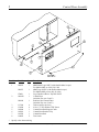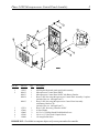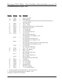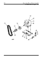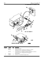
1
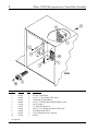
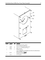
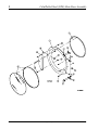
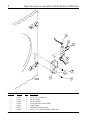
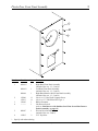
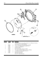
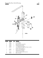
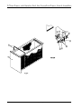
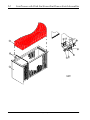
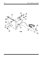
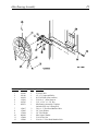
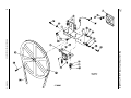
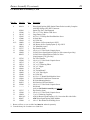
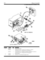
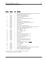
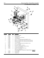
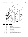
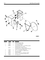
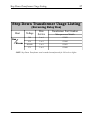
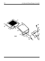
AD-81 Parts Manual
24 VAC Phase 5
1992 thru 2000
American Dryer Corporation
88 Currant Road
Fall River, MA 02720-4781
Telephone: (508) 678-9000 / Fax: (508) 678-9447
E-mail: [email protected]
www.amdry.com
ADC Part No. 450148- 19
Retain This Manual In A Safe Place For Future Reference
American Dryer Corporation products embody advanced concepts in engineering, design, and safety. If this product is
properly maintained, it will provide many years of safe, efficient, and trouble-free operation.
ONLY qualified technicians should service this equipment.
OBSERVE ALL SAFETY PRECAUTIONS displayed on the equipment or specified in the installation manual included with
the dryer.
The following “FOR YOUR SAFETY” caution must be posted near the dryer in a prominent location.
FOR YOUR SAFETY
POUR VOTRE SÉCURITÉ
Do not store or use gasoline or
other flammable vapors and
liquids in the vicinity of this or
any other appliance.
Ne pas entreposer ni utiliser d’essence
ni d’autres vapeurs ou liquides
inflammables à proximité de cet
appareil ou de tout autre appareil.
We have tried to make this manual as complete as possible and hope you will find it useful. ADC reserves the right to make
changes from time to time, without notice or obligation, in prices, specifications, colors, and material, and to change or
discontinue models.
Important
For your convenience, log the following information:
DATE OF PURCHASE ____________________________________________________
MODEL NO.
AD-81
__________________
RESELLER’S NAME _______________________________________________________________________________________
Serial Number(s)
________________________________________________________________________________________
________________________________________________________________________________________
________________________________________________________________________________________
Replacement parts can be obtained from your reseller or the ADC factory. When ordering replacement parts from the factory,
you can FAX your order to ADC at (508) 678-9447 or telephone your order directly to the ADC Parts Department at (508)
678-9000. Please specify the dryer model number and serial number in addition to the description and part number, so that
your order is processed accurately and promptly.
The illustrations on the following pages may not depict your particular dryer exactly. The illustrations are a composite of the
various dryer models. Be sure to check the descriptions of the parts thoroughly before ordering.
“IMPORTANT NOTE TO PURCHASER”
Information must be obtained from your local gas supplier on the instructions
to be followed if the user smells gas. These instructions must be posted in a
prominent location near the dryer.
Table of Contents
Control Door Assembly ....................................................................................................................................... 2
Phase 5 OPL Microprocessor Control Panel Assembly ..................................................................................... 3
Phase 5 OPL Microprocessor Control Box Assembly ........................................................................................ 4
Cold Rolled Steel (CRS) Door Front Panel Assembly ........................................................................................ 5
Cold Rolled Steel (CRS) Main Door Assembly .............................................................................................. 6, 7
Main Door Switch Assembly Cold Rolled Steel (CRS) Door ............................................................................. 8
Plastic Door Front Panel Assembly ..................................................................................................................... 9
Plastic Main Door Assembly ............................................................................................................................. 10
Plastic Main Door Switch Housing ................................................................................................................... 11
Lint Drawer with Stainless Steel Lint Screen/Lint Drawer Switch Assemblies ......................................... 12, 13
Lint Drawer with Cloth Lint Screen/Lint Drawer Switch Assemblies ....................................................... 14, 15
Sensor Bracket Assembly ........................................................................................................................... 16, 17
Basket (Tumbler)/Support Assembly ................................................................................................................. 18
Idler Bearing Assembly ..................................................................................................................................... 19
Basket (Tumbler) Bearing Assembly .......................................................................................................... 20, 21
Reversing, T.E.F.C. Drive Motor/Fan Shaft Motor Mount Assembly
For Models Mfd. as of August 7, 1995 ................................................................................................... 22, 23
Reversing, T.E.F.C. Motor - Drive/Fan Motor Mount Assembly
For Models Mfd. prior to August 7, 1995 ................................................................................................ 24, 25
Reversing Blower Motor Assembly
For Models Mfd. as of August 7, 1995 ................................................................................................... 26, 27
Burner Assembly II
For Models Mfd. as of January 2, 1996 .................................................................................................. 28, 29
Burner Assembly
For Models Mfd. prior to January 2, 1996 .............................................................................................. 30, 31
Reversing Rear Control Box Assembly
For Models Mfd. as of January 1, 1995 ........................................................................................................ 32
Reversing Rear Control Box Assembly
For Models Mfd. prior to January 1, 1995 .................................................................................................... 33
Sail Switch Assembly ........................................................................................................................................ 34
Step Down Transformer Usage Listing ............................................................................................................ 35
Air Operated Steam Damper Assembly ...................................................................................................... 36, 37
Outer Top/Back Guard Assemblies ................................................................................................................... 38
Additional Parts Available .................................................................................................................................. 39
2
Control Door Assembly
Illus. No.
1
2
3
4
5
6
7
8
*
2
Part No.
Qty.
882052
1
881053
1
870011
881045*
1
1
881046
1
117604
150300
102600
102601
102502
160005
4
4
1
1
1
2
Description
ADC Metal Logo ONLY (with double adhesive tape)
For Models Mfd. as of July 28, 1998
ADC Logo ONLY (with double adhesive tape)
For Models Mfd. prior to July 28, 1998
Logo Double Adhesive Tape Kit ONLY
Control Door
(includes illus. nos. 2 and 3)
Stainless Steel Control Door
(includes illus. nos. 2 and 3)
Gasket (sold by the foot)
#10 x 1/2” Hex Washer TEK Screw
Control Door Rod Support Catch
Control Door Retainer Clip
Control Door Rod
Turn Latch
Specify color when ordering.
American Dryer Corporation
450148 - 19
Phase 5 OPL Microprocessor Control Panel Assembly
Illus. No.
1
2
3
4
5
6
7
Part No.
Qty.
112535
881032
881033
881034
1
1
1
1
881035
1
137231
153010
150005
150309
136048
1
2
2
1
1
3
Description
OPL English Keyboard (touch pad) Label Assembly
Microprocessor Control Panel ONLY
Microprocessor Control Panel ONLY with Battery Bracket
Phase 5 OPL Reversing Microprocessor Control Panel Assembly Complete
(includes illus. nos. 1 through 5 and 7)
Phase 5 OPL Reversing Microprocessor Control Panel Assembly
with Battery Bracket Clip
(includes illus. nos. 1 through 5 and 7)
Phase 5 OPL Reversing Controller ONLY
#6 Star Washer
#6-32 x 3/4” Phillips Round Head Machine Screw
#10-16 x 1/2” Hex Head Crimptite Screw
1/8-Amp (Slo-Blo) Fuse
IMPORTANT: Check label on computer chip to verify correct part number for controller.
450148 - 19
www.amdry.com
3
4
Phase 5 OPL Microprocessor Control Box Assembly
Illus. No.
1
2
3
4
5
6
7
8
9
10
*
4
Part No.
141403
150300
120715
150002
151000
136057
150301
136008
122641
122706
Qty.
1
2
1
2
2
*
*
*
1
*
Description
24 VAC Transformer
#10 x 1/2” Hex Washer TEK Screw
30-Position Terminal Block
#6-32 x 1” Phillips Round Head Machine Screw
#6-32 Pal Nut
1/2-Amp (Slo-Blo) Fuse
#8-18 x 7/16” Phillips Pan Head TEK Screw
Fuse Block/Strip ONLY
15-Pin Microprocessor Connector
Socket
As required.
American Dryer Corporation
450148 - 19
Cold Rolled Steel (CRS) Door Front Panel Assembly
Illus. No.
Part No.
Qty.
1
881994
1
2
3
4
150309
150313
121405
---------
11
11
1
1
5
881987
1
6
154215
2
450148 - 19
5
Description
Right Hand Front Panel Complete
(for cold rolled steel [CRS] door)
#10-16 x 1/2” Hex Head Crimptite Screw
#10-16 x 1/2” TORX Plus BTN Type 1
Rubber Grommet
Lint Drawer Switch
(refer to Lint Drawer with Stainless Steel Lint Screen/Lint Drawer
Switch Assembly on page 12)
Friction Door Latch Kit
(includes illus. nos. 5 and 6)
5/32” Pop Rivet
www.amdry.com
5
6
6
Cold Rolled Steel (CRS) Main Door Assembly
American Dryer Corporation
450148 - 19
Cold Rolled Steel (CRS) Main Door Assembly
Illus. No.
1
2
3
4
5
6
7
8
9
10
11
12
13
14
15
450148 - 19
Part No.
Qty.
881150
1
881207
1
102354
170730
170731
881152
1
1
1
1
881208
1
150445
150443
153031
881151
2
2
1
1
881209
1
150445
150443
150683
150682
2
2
3
3
152014
151010
151009
150120
150683
150682
3
1
1
1
3
3
152014
881210
170333
102210
102360
3
1
1
1
1
170730
1
7
Description
Black Main Door Assembly Complete
(includes illus. nos. 1, 2, and 8 through 15)
Stainless Steel Main Door Assembly Complete
(includes illus. nos. 1, 2, and 8 through 15)
Door Gasket
Clear Glass and Gasket Adhesive (10.3 oz. cartridge)
Black Glass and Gasket Adhesive (10.3 oz. cartridge)
Black Top Hinge Block Assembly
(includes illus. nos. 3 and 4)
Stainless Steel Top Hinge Block Assembly
(includes illus. nos. 3 and 4)
1/4-20 x 7/8” Black Cap Head Setscrew
1/4-20 x 7/8” Stainless Steel Cap Head Setscrew
1/4” Nylon Washer
Black Bottom Hinge Block Assembly
(includes illus. nos. 5, 6, and 7)
Stainless Steel Bottom Hinge Block Assembly
(includes illus. nos. 5, 6, and 7)
1/4-20 x 7/8” Black Cap Head Setscrew
1/4-20 x 7/8” Stainless Steel Cap Head Setscrew
1/4-20 x 5/8” Black Carriage Bolt
1/4-20 x 5/8” Stainless Steel Carriage Bolt
(for models with stainless steel doors)
1/4-20 Free Spin Wash Nut
#10-32 Black Hex Acorn Nut
#10-32 Stainless Steel Hex Acorn Nut
Door Latch Screw
1/4-20 x 5/8” Black Carriage Bolt
1/4-20 x 5/8” Stainless Steel Carriage Bolt
(for models with stainless steel doors)
1/4-20 Free Spin Wash Nut
Black Main Door Handle ONLY
Stainless Steel Main Handle ONLY
20-7/16” Door Glass
Glass/Door Gasket Tape
(for models mfd. as of December 13, 2000)
Clear Glass and Gasket Adhesive (10.3 oz. cartridge)
(for models mfd. prior to December 13, 2000)
www.amdry.com
7
8
Main Door Switch Assembly Cold Rolled Steel (CRS) Door
Illus. No.
1
2
3
4
5
6
7
8
Part No.
153566
152013
153010
137005
122636
881211
150301
Qty.
2
2
2
1
2
1
2
Description
#6-32 x 7/8” Clinch Stud
#6-32 Hex Nut
#6 Star Washer
Single-Pole Door Switch (SDS)
Flag Terminal
Main Door Switch Housing
#8-18 x 7/16” Phillips Pan Head TEK Screw
American Dryer Corporation
450148 - 19
Plastic Door Front Panel Assembly
Illus. No.
Part No.
Qty.
1
881041*
1
881043*
1
881044
1
3
4
150309
150313
121405
---------
11
11
1
1
5
881987
1
6
154215
2
2
*
9
Description
Right Hand Front Panel Assembly
(includes illus. nos. 1, 3, 5, and 6)
Left Hand Front Panel Assembly
(includes illus. nos. 1, 3, 5, and 6)
Right Hand Stainless Steel Front Panel Assembly
(includes illus. nos. 1, 3, 5, and 6)
#10-16 x 1/2” Hex Head Crimptite Screw
#10-16 x 1/2” TORX Plus BTN Type 1
Rubber Grommet
Lint Drawer Switch
(refer to Lint Drawer with Stainless Steel Lint Screen/Lint Drawer
Switch Assembly on page 12)
Friction Door Latch Kit
(includes illus. nos. 5 and 6)
5/32” Pop Rivet
Specify color when ordering.
450148 - 19
www.amdry.com
9
10
Illus. No.
Part No.
Qty.
1
881421
1
2
3
4
5
6
800448
150410
152014
102349
102212
170730
150448
170319
150431
4
4
1
1
1
1
4
4
1
7
8
9
10
Plastic Main Door Assembly
Description
Gray Plastic Main Door Assembly Complete with Mechanical Fasteners
(includes illus. nos. 1 and 5 through 9)
12-1/2” Stainless Steel Main Door Hinge Assembly
#10-24 x 3/8” Phillips Pan Head Taptite Screw
1/4-20 Free Spin Wash Nut
Main Door Gasket
20-7/16” Door Glass with Four (4) Holes
Clear Glass and Gasket Adhesive (10.3 oz. cartridge)
1/2” Stainless Steel Flat Head Allen Screw
Door Glass (nylon) Spacer
Main Door Latch Screw
(#10 x 7/16” dome hex head)
American Dryer Corporation
450148 - 19
Plastic Main Door Switch Housing
Illus. No.
Part No.
Qty.
1
2
3
4
5
6
152013
153008
137005
121028
154281
800448
2
2
1
2
2
1
7
8
153565
881246
2
1
9
10
150201
121405
2
1
450148 - 19
11
Description
#6-32 Hex Nut
#6 Lock Washer
Single-Pole Door Switch (SDS)
Insulated Female Terminal
3/8” Standard Nylon Spacers
12-1/2” Stainless Steel Main Door Hinge Assembly
(includes illus. nos. 6 and 7)
#6-32 x 1” Self Clinching Stud
Main Door Switch Housing
(includes illus. nos. 7 and 8)
#10-32 x 1/4” Phillips Pan Head Screw
Rubber Grommet
www.amdry.com
11
12 Lint Drawer with Stainless Steel Lint Screen/Lint Drawer Switch Assemblies
12
American Dryer Corporation
450148 - 19
Lint Drawer with Stainless Steel Lint Screen/Lint Drawer Switch Assemblies
Illus. No.
1
2
3
4
5
Part No.
Qty.
6
882871
117605
122116
122605
122701
122801
800478
1
5
1
2
4
1
1
7
8
9
304135
150301
122700
122604
1
2
4
2
450148 - 19
13
Description
Lint Drawer with Stainless Steel Screen
Gasket (sold by the foot)
Lint Drawer Switch
4-Pin Socket Connector
Socket Terminal ONLY
Socket Terminal Extraction Tool
Lint Drawer Switch Box Assembly
(includes illus. nos. 4 through 7)
Lint Drawer Switch Box ONLY
#8-18 x 7/16” Phillips Pan Head TEK Screw
Pin Terminal ONLY
4-Pin Connector ONLY
www.amdry.com
13
14
14
Lint Drawer with Cloth Lint Screen/Lint Drawer Switch Assemblies
American Dryer Corporation
450148 - 19
Lint Drawer with Cloth Lint Screen/Lint Drawer Switch Assemblies
Illus. No.
Part No.
Qty.
1
881463*
1
881464
1
881042*
1
881062
1
117605
802205
122116
122605
122701
122801
800478
5
1
1
2
4
1
1
800264
1
304135
1
304034
1
150301
122700
122604
2
4
2
2
3
4
5
6
7
8
9
10
*
15
Description
Lint Drawer Assembly - Type II
(includes illus. nos. 1 and 2 Only)
For Models Mfd. as of October 7, 1996
Stainless Steel Lint Drawer Assembly - Type II
(includes illus. nos. 1 and 2 Only)
For Models Mfd. as of October 7, 1996
Lint Drawer Assembly - Type I
(includes illus. nos. 1 and 2 Only)
For Models Mfd. prior to October 7, 1996
Stainless Steel Lint Drawer Assembly - Type I
(includes illus. nos. 1 and 2 Only)
For Models Mfd. prior to October 7, 1996
Gasket (sold by the foot)
Lint Screen Assembly
Lint Drawer Switch
4-Pin Socket Connector
Socket Terminal ONLY
Socket Terminal Extraction Tool
Lint Drawer Switch Box Assembly
(includes illus. nos. 4 through 7)
For Models Mfd. as of January 1, 1999
Lint Drawer Switch Box Assembly
For Models Mfd. prior to January 1, 1999
Lint Drawer Switch Box ONLY
For Models Mfd. as of January 1, 1999
Lint Drawer Switch Box ONLY
For Models Mfd. prior to January 1, 1999
#8-18 x 7/16” Phillips Pan Head TEK Screw
Pin Terminal ONLY
4-Pin Connector ONLY
Specify color when ordering.
450148 - 19
www.amdry.com
15
16
16
Sensor Bracket Assembly
American Dryer Corporation
450148 - 19
17
Sensor Bracket Assembly
Illus. No.
Part No.
Qty.
1
880251
1
2
3
4
5
6
122605
122701
154007
150000
802174
1
4
2
2
1
7
8
9
10
11
12
--
323626
130301
153010
152000
150301
122604
122700
122801
1
1
2
2
2
1
4
1
450148 - 19
Description
1/4” Temperature Sensor Probe Assembly
(includes illus. nos. 1 through 4)
4-Pin Socket Connector ONLY
Socket Terminal ONLY
1/4” Tinnerman Push On Fastener
#6-32 x 1/4” Round Head Machine Screw
Sensor Bracket Assembly Complete
(includes illus. nos. 1 through 9)
Temperature Sensor Bracket ONLY
225° Manual Reset Thermostat
#6 Star Washer
#6-32 Hex Nut
#8-18 x 7/16” Phillips Pan Head TEK Screw
4-Pin Connector ONLY
Pin Terminal ONLY
Pin/Extraction Tool
www.amdry.com
17
18
Illus. No.
1
2
3
4
5
6
7
8
9
10
11
-18
Basket (Tumbler)/Support Assembly
Part No.
Qty.
880818
1
880827
1
154210
301308
150500
100905
153004
800615
152005
153005
153004
116000
401010
40
4
1
4
4
1
4
4
4
1
1
Description
Basket (tumbler) ONLY without Felt Collar
(includes illus. nos. 1, 2, and 3)
Reversing Basket (tumbler) and Support Assembly Complete
(includes illus. nos. 1 through 11)
5/32” x 3/16” Pop Rivet
Basket (tumbler) Rib ONLY
5/16-18 x 34” Socket Button Head Screw
3/8-16 x 37” Tie Rod
3/8” Flat Washer
Reversing Basket (tumbler) Support ONLY
3/8-16 Hex Nut
3/8” Lock Washer
3/8” Flat Washer
Felt Collar ONLY
#847 Adhesive For Felt Collar (5 oz. tube)
American Dryer Corporation
450148 - 19
19
Idler Bearing Assembly
Illus. No.
Part No.
Qty.
1
2
3
4
5
6
100106
101140
100158
154301
100705
882576
1
1
1
2
1
1
7
8
9
10
11
12
150617
153005
153004
801009
152004
150509
2
2
2
1
1
1
450148 - 19
Description
5L-690 V-Belt
14” x 3” Compound Pulley
4L-550 V-Belt (idler to motor)
5/16-18 x 1” Allen Setscrew
3/16” x 3/16” x 1-3/8” Key
Idler Bearing Assembly Complete
(includes illus. nos. 5 through 12)
3/8-16 x 1” Hex Head Machine Bolt
3/8” Lock Washer
3/8” Flat Washer
Idler Square Washer
5/16-18 Hex Nut
5/16-18 x 3” Hex Head Machine Bolt
www.amdry.com
19
20
20
450148 - 19
Basket (Tumbler) Bearing Assembly
American Dryer Corporation
Basket (Tumbler) Bearing Assembly
Illus. No.
1
2
3
4
Part No.
Qty.
880220
153025
152050
882545
1
4
4
1
882544
1
882542
1
5
882543
880779
1
1
6
7
8
9
10
11
12
13
14
15
16
17
880202
150601
153004
153004
153005
152005
154326
152004
150621
153002
153004
150501
102120
1
2
2
2
2
2
2
2
2
4
6
4
1
18
19
20
21
22
23
24
824807
100735
101118
101119
100106
150610
152004
1
1
1
1
1
2
2
450148 - 19
21
Description
1-3/4” Flange Bearing
9/16” Lock Washer
9/16-12 Hex Nut
Pillow Block Bearing Assembly Complete with Rotational Sensor
(includes illus. nos. 4 through 18, 23, and 24)
Pillow Block Bearing Assembly
(includes illus. nos. 4 through 17, 23, and 24)
Pillow Block Bearing Platform ONLY
(for models with rotational sensor only)
Pillow Block Bearing Platform ONLY
1-3/8” Pillow Block Bearing
(for models with rotational sensor only)
1-3/8” Pillow Block Bearing
3/8-16 x 2” Hex Bolt
3/8” Flat Washer
3/8” Flat Washer
3/8” Lock Washer
3/8-16 Hex Nut
5/16-24 x 3/8” Setscrew
5/16-18 Hex Nut
5/16-18 x 1-1/2” Tap Bolt
5/16” Lock Washer
3/8” Flat Washer
5/16-18 x 3/4” Tap Bolt
Sintered 8 Magnet
(for models with rotational sensor only)
Rotational Sensor Assembly
Shaft Key
18-3/4” Pulley
1-3/8” Taper Lock Bushing
5L-690 V-Belt (basket [tumbler] to idler)
5/16-18 x 1-1/2 Allen Setscrew
5/16-18 Hex Nut
www.amdry.com
21
22
Reversing, T.E.F.C. Drive Motor/Fan Shaft Motor Mount Assembly
For Models Mfd. as of August 7, 1995
22
American Dryer Corporation
450148 - 19
Reversing, T.E.F.C. Drive Motor/Fan Shaft Motor Mount Assembly
23
For Models Mfd. as of August 7, 1995
Illus. No.
1
2
Part No.
Qty.
100158
101130
1
1
101139
1
181003
150501
153002
153001
153004
153005
150601
100706
101152
1
4
4
4
4
4
4
1
1
101194
1
101195
1
101147
1
101148
1
13
14**
15
317400
100802
880879
1
2
2
16
17
18
19
20
21
116014
802231
117604
882670
153050
152006
1
1
5
1
1
2
3*
4
5
6
7
8
9
10
11
12
Description
4L-550 V-Belt
5/8” x 2-1/2” Motor Pulley
(for 60 Hz models Only)
5/8” x 2-3/4” Motor Pulley
(for 50 Hz models Only)
1/2 HP 3ø Totally Enclosed, Fan Cooled (T.E.F.C.) Motor (50/60 Hz)
5/16-18 x 3/4” Machine Bolt
5/16” Lock Washer
5/16” Flat Washer
3/8” Flat Washer
3/8” Lock Washer
3/8-16 x 2” Machine Bolt
5/16” x 5/16” x 1-3/8” Key
5H x 1-3/8” Bushing
(for 60 Hz gas models and 50/60 Hz steam models)
SDS x 1-3/8” Bushing
(for 60 Hz steam models Only)
2B x 4.4 Pulley
(for gas models - 50/60 Hz)
2B x 4.8 Pulley
(for 60 Hz steam models Only)
2B x 4.0 Pulley
(for 50 Hz steam models Only)
Impellor/Fan Shaft
Retaining Ring
1-3/8” Pillow Block Bearing with Cone Point Nylon Patch Setscrew
and Grease Fitting
3” x 3” Fan Shaft Gasket
Motor Mount ONLY (does not include gasket)
Gasket (sold by the foot)
16” Impellor (fan)
1/2” Flat Washer
1/2-20 Left Hand Jam Nut
* Check part number on motor data label to verify correct motor.
** For some models manufactured prior to March 1, 1995.
450148 - 19
www.amdry.com
23
24
Reversing, T.E.F.C. Motor - Drive/Fan Motor Mount Assembly
For Models Mfd. prior to August 7, 1995
Illus. No.
1
2
3*
4
5
6
7
8
9
10
11
12
24
Part No.
Qty.
100158
101130
1
1
101139
1
181003
150501
153002
153001
153004
153005
150601
100706
101152
1
4
4
4
4
4
4
1
1
101194
1
101195
1
101147
101148
1
1
Description
4L-550 V-Belt
5/8” x 2-1/2” Motor Pulley
(for 60 Hz models Only)
5/8” x 2-3/4” Motor Pulley
(for 50 Hz models Only)
1/2 HP 3ø Totally Enclosed, Fan-Cooled (T.E.F.C.) Motor (50/60 Hz)
5/16-18 x 3/4” Machine Bolt
5/16” Lock Washer
5/16” Flat Washer
3/8” Flat Washer
3/8” Lock Washer
3/8-16 x 2” Machine Bolt
5/16” x 5/16” x 1-3/8” Key
SH x 1-3/8” Bushing
(for 60 Hz gas models and 50/60 Hz steam models)
SDS x 1-3/8” Bushing
(for 60 Hz steam models Only)
2B x 4.4 Pulley
(for 50/60 Hz gas models Only)
2B x 4.8 Pulley (for 60 Hz steam models Only)
2B x 4.0 Pulley (for 50 Hz steam models Only)
American Dryer Corporation
450148 - 19
Reversing, T.E.F.C. Motor - Drive/Fan Motor Mount Assembly (continued) 25
For Models Mfd. prior to August 7, 1995
Illus. No.
Part No.
Qty.
13
14**
15
317400
100802
880879
1
2
2
16
17
18
19
20
21
22
23***
152005
150619
802175
117604
882670
153050
152006
100169
2
2
1
5
1
1
2
2
100156
2
100119
2
100156
2
100706
101138
101147
1
1
1
101177
1
101185
1
882078
152005
153005
153004
332198
821012
116014
1
4
4
4
1
1
1
24
25
26
27*
28
29
30
31
32
33
Description
Impellor/Fan Shaft
Retaining Rings
1-3/8” Pillow Block Bearing with Cone Point Nylon Patch Setscrew
and Grease Fitting
3/8-16 Hex Nut
3/8-16 x 3” Bolt
Motor Mount ONLY (does not include gasket)
Gasket (sold by the foot)
16” Impellor (fan)
1/2” Flat Washer
1/2-20 Left Hand Jam Nut
5L-350 V-Belt
(for 60 Hz gas models Only)
For Models Mfd. as of March 16, 1995
5L-330 V-Belt
(for 50/60 Hz steam models Only)
For Models Mfd. as of March 16, 1995
5L-320 V-Belt
(for 60 Hz gas models and 50/60 Hz steam models Only)
For Models Mfd. prior to March 16, 1995
5L-330 V-Belt
(for 50 Hz gas models Only)
5/16” x 5/16” x 1-3/8” Key
SDS x 1-1/8” Bushing
2B x 4.8 Pulley
(for 60 Hz gas models Only)
2B x 5.8 Pulley
(for 50 Hz gas models Only)
2B x 6.2 Pulley
(for 50/60 Hz steam models Only)
3 HP Motor
3/8-16 Hex Nut
3/8” Lock Washer
3/8” Flat Washer
Adjustment Plate
Bolt Plate Assembly
3” x 3” Fan Shaft Gasket
* Check part number on motor data label to verify correct motor.
** For some models manufactured prior to March 1, 1995.
*** Replace in matched sets (both belts).
450148 - 19
www.amdry.com
25
26
Reversing Blower Motor Assembly
For Models Mfd. as of August 7, 1995
26
American Dryer Corporation
450148 - 19
Reversing Blower Motor Assembly
27
For Models Mfd. as of August 7, 1995
Illus. No.
1*
2
3
4
5**
6
7
8
9
10
11
12
13
14
15
Part No.
Qty.
100169
2
100156
2
100119
2
100156
2
100706
101138
101147
1
1
1
101177
1
101185
1
882078
152005
153005
153004
802253
802232
152034
152005
150501
153005
153004
1
4
4
4
1
1
2
4
4
4
4
Description
5L-350 V-Belt
(for 60 Hz gas models Only)
For Models Mfd. as of March 16, 1995
5L-320 V-Belt
(for 50/60 Hz steam Only)
For Models Mfd. as of March 16, 1995
5L-320 V-Belt
(for 60 Hz gas models and 50/60 Hz steam models)
For Models Mfd. prior to March 16, 1995
5L-330 V-Belt
(for 50 Hz gas models Only)
5/16” x 5/16” x 1-3/8” Key
Single-Pole Door Switch (SDS) x 1-1/8” Bushing
2B x 4.8 Pulley
(for 60 Hz gas models Only)
2B x 5.8 Pulley
(for 50 Hz gas models Only)
2B x 6.2 Pulley
(for 50/60 Hz steam models Only)
3 HP Motor
3/8-16 Hex Nut
3/8” Lock Washer
3/8” Flat Washer
Adjustment Plate
Adjustment Angle
3/8-16 x 3-1/2” Bolt
3/8-16 Hex Nut
5/16-18 x 3/4” Machine Bolt
3/8” Lock Washer
3/8” Flat Washer
* Replace in matched sets (both belts).
** Check part number on motor data label to verify correct motor.
450148 - 19
www.amdry.com
27
28
Burner Assembly II
For Models Mfd. as of January 2, 1996
Illus. No.
Part No.
Qty.
1
802237
881258*
1
1
881257*
1
802240
150309
1
4
2
3
28
Description
Burner Box ONLY
Natural Gas Burner Assembly II Complete Less Orifice
(includes illus. nos. 1 through 9 and 11 through 32)
Liquid Propane (L.P.) Burner Assembly II Complete Less Orifice
(includes illus. nos. 1 through 9 and 11 through 32)
Burner Shield
#10-16 x 1/2” Hex Head Crimptite Screw
American Dryer Corporation
450148 - 19
29
Burner Assembly II (continued)
For Models Mfd. as of January 2, 1996
Illus. No.
4
Part No.
Qty.
880134
1
305410
150300
141105
150103
153000
151001
140856
140811
141210
323737
150309
128928
881052
2
4
4
4
4
4
4
1
1
2
1
1
15
16
17
18
19
20
21
22
23
24
25
26
27
28
29
323763
150309
142715
142511
142709
142601
141300
142829
151000
151001
130201
319704
824533
150309
---------
1
2
1
1
2
1
1
1
2
2
1
1
1
2
1
30
31
32
-33
34
323737
150309
142924
881016**
882627
150299
1
2
1
1
1
4
5
6
7
8
9
10**
11
12
13
14
Description
Direct Spark Ignition (DSI) Ignitor/Flame-Probe Assembly Complete
with High Voltage (HV) Wire Connector
Ignitor Gap Tool...Not Illustrated
#10 x 1/2” Hex Washer TEK Screw
Large Burner Tube
#8-32 x 1/2” Phillips Pan Head Machine Screw
#8 Steel Burr
#8-32 Pal Nut
#23 Burner Orifice (natural gas) ONLY
#41 Burner Orifice (liquid propane [L.P.]) ONLY
3/4” Manifold (4-port)
Pipe Bracket (bent)
#10-16 x 1/2” Hex Head Crimptite Screw
24 VAC Direct Spark Ignition (DSI) Gas Valve (natural gas Only)
24 VAC Direct Spark Ignition (DSI) Gas Valve
(liquid propane [L.P]. gas Only)
Gas Valve Bracket
#10-16 x 1/2” Hex Head Crimptite Screw
1/2” x 2” Nipple
3/4” x 1/2” Reducing Elbow
3/4” x 2” Nipple
3/4” Union
3/4” Union Shutoff
3/4” x 20” Pipe Nipple
#6-32 Pal Nut
#6-32 x 1/2” Round Head Machine Screw
330º Manual Hi-Limit Reset Thermostat
Hi-Limit Mounting Bracket
Sail Switch to Hi-Limit Harness
#10-16 x 1/2” Hex Head Crimptite Screw
Sail Switch
(refer to Sail Switch Assembly on page 34)
Pipe Bracket (bent)
#10-16 x 1/2” Hex Head Crimptite Screw
1” to 3/4” Reducing Coupling
ADG-81 Burner Liquid Propane (L.P.) Conversion Kit with Orifice
ADC Direct Spark Ignition (DSI) Module
#10 x 1” Hex Washer Self Drilling Screw
* Burner orifices are not included and must be ordered separately.
** Consult factory for elevations over 2,000 feet.
450148 - 19
www.amdry.com
29
30
Burner Assembly
For Models Mfd. prior to January 2, 1996
Illus. No.
Part No.
Qty.
1
802206
881050*
1
1
881051*
1
323709
150309
1
2
2
3
30
Description
Burner Box ONLY
Natural Gas Burner Assembly II Complete Less Orifice
(includes illus. nos. 1 through 9 and 11 through 30)
Liquid Propane (L.P.) Burner Assembly II Complete Less Orifice
(includes illus. nos. 1 through 9 and 11 through 30)
Burner Shield
#10-16 x 1/2” Hex Head Crimptite Screw
American Dryer Corporation
450148 - 19
31
Burner Assembly (continued)
For Models Mfd. prior to January 2, 1996
Illus. No.
4
Part No.
Qty.
880134
1
305410
150300
141105
150103
153000
151001
140856
140811
141210
332117
150300
128928
881052
2
4
4
4
4
4
4
1
1
2
1
1
15
16
17
18
19
20
21
22
23
24
25
26
142715
142511
142829
332117
150309
824533
150309
319704
151000
151001
130201
---------
1
1
1
2
4
1
4
1
2
2
1
1
27
28
29
30
-31
32
141300
142709
142601
142924
881016**
882627
150299
1
2
1
1
1
1
4
5
6
7
8
9
10**
11
12
13
14
Description
Direct Spark Ignition (DSI) Ignitor/Flame-Probe Assembly Complete
with High Voltage (HV) Wire Connector
Ignitor Gap Tool...Not Illustrated
#10 x 1/2” Hex Washer TEK Screw
Large Burner Tube
#8-32 x 1/2” Phillips Pan Head Machine Screw
#8 Steel Burr
#8-32 Pal Nut
#23 Burner Orifice (natural gas) ONLY
#41 Burner Orifice (liquid propane [L.P.]) ONLY
1/2” 4-Port Manifold
Pipe Bracket
#10 x 1/2” Hex Washer TEK Screw
24 VAC Direct Spark Ignition (DSI) Gas Valve (natural gas Only)
24 VAC Direct Spark Ignition (DSI) Gas Valve
(liquid propane [L.P.] gas Only)
1/2” x 2” Nipple
3/4” x 1/2” Reducing Elbow
3/4” x 20” Pipe
Pipe Bracket
#10-16 x 1/2” Hex Head Crimptite Screw
Sail Switch to Hi-Limit Harness
#10-16 x 1/2” Hex Head Crimptite Screw
Hi-Limit Mounting Bracket
#6-32 Pal Nut
#6-32 x 1/2” Round Head Machine Screw
330º Manual Hi-Limit Reset Thermostat
Sail Switch
(refer to Sail Switch Assembly on page 34)
3/4” Union Shutoff
3/4” x 2” Nipple
3/4” Union
1” to 3/4” Reducing Coupling
ADG-81 Burner Liquid Propane (L.P.) Conversion Kit with Orifice
ADC Direct Spark Ignition (DSI) Module
#10 x 1” Hex Washer Self Drilling Screw
* Burner orifices are not included and must be ordered separately.
** Consult factory for elevations over 2,000 feet.
450148 - 19
www.amdry.com
31
32
Reversing Rear Control Box Assembly
For Models Mfd. as of January 1, 1995
Illus. No.
Part No.
Qty.
1
2
3
4
5
6
7
8
9
10
11
12
13
14
323743
137013
137060
132445
150103
132467
132468
152004
150103
153002
882386
150008
120701
150300
---------
1
4
1
1
4
1
1
1
3
1
1
2
1
4
1
15
16
17
151000
151001
121012
2
4
1
32
Description
Relay Panel ONLY
Nylon Standoff
Arc Suppressor (A.S.) Board
3 HP Contactor
#8-32 x 3/4” Phillips Round Head Machine Screw
Blower Overload (for 208 volt and 230 volt models Only)
Blower Overload (for 380 volt and 600 volt models Only)
5/16-18 Hex Nut
#8-32 x 3/4” Phillips Round Head Machine Screw
5/16” Lock Washer
Reversing Contactor - 24 VAC
#6-32 x 1-1/4” Round Head Machine Screw
4-Position Terminal Block
#10 x 1/2” Hex Washer TEK Screw
Step Down Transformer
(refer to Step Down Transformer Usage Listing on page 35)
#6-32 Pal Nut
#8-32 Pal Nut
Ground Lug
American Dryer Corporation
450148 - 19
Reversing Rear Control Box Assembly
33
For Models Mfd. prior to January 1, 1995
Illus. No.
1
2
3
4
5
6
7
8
9
10
11
12
13
14
15
450148 - 19
Part No.
322812
137060
137013
882386
150103
151001
153002
152004
132445
150103
151001
120701
150008
151000
121300
Qty.
1
1
4
1
2
2
1
1
1
2
2
1
2
2
3
Description
Relay Panel ONLY
Arc Suppressor (A.S.) Board
Nylon Standoff
Reversing Contactor - 24 VAC
#8-32 x 3/4” Phillips Round Head Machine Screw
#8-32 Pal Nut
5/16-18 Lock Washer
5/16-18 Hex Nut
3 HP Contactor
#8-32 x 3/4” Phillips Round Head Machine Screw
#8-32 Pal Nut
4-Position Terminal Block
#6-32 x 1-1/4” Slotted Round Head Machine Screw
#6-32 Pal Nut
Open/Closed Bushing
www.amdry.com
33
34
Illus. No.
1
2
3
4
5
6
7
8
9
10
34
Sail Switch Assembly
Part No.
Qty.
105500
319202
154002
802800
1
1
1
1
802801
1
150300
150303
122200
802799
150309
154004
2
2
1
1
2
1
Description
Sail Switch Actuator Rod
Sail Switch Damper (flat)
1/8” Push On Fastener
Sail Switch Box with Cover and Bracket ONLY
(includes illus. nos. 4, 8, and 9)
Sail Switch Box Assembly Complete
(includes illus. nos. 1 through 4 and 6 through 10)
#10 x 1/2” Hex Washer TEK Screw
#4 x 3/4” Pan Head “A” Machine Screw
Sail Switch ONLY
Sail Switch Box Cover and Bracket ONLY
#10-16 x 1/2” Hex Head Crimptite Screw
Twin Speed Nut
American Dryer Corporation
450148 - 19
35
Step Down Transformer Usage Listing
Step Down Transformer Usage Listing
Heat
Gas
Steam
(Reversing Relay Box)
Wire
Transformer Part Number
Voltage
Microprocessor Models
Service
380
3 or 4
132059
416
3 or 4
132062
460/480
3 or 4
132053
575
3 or 4
132050
NOTE: Step Down Transformer used on models manufactured for 380 volts or higher.
450148 - 19
www.amdry.com
35
36
36
Air Operated Steam Damper Assembly
American Dryer Corporation
450148 - 19
Air Operated Steam Damper Assembly
Illus. No.
Part No.
Qty.
1
2
3
4
5
6
7
165009
153002
152004
152002
153007
820321
803415
1
6
6
4
4
2
1
8
9
10
11
12
13
14
15
16
17
18
19
20
21
22
23
24
25
26
27
28
29
30
153007
152002
115995
102350
151007
152007
100497
100492
152002
153007
100472
143110
100472
100496
143238
100498
150002
153010
152000
330987
152002
153007
100520
4
4
108
1
1
1
1
1
4
4
1
1
1
1
1
1
2
2
2
1
2
2
1
450148 - 19
37
Description
Steam Coil Assembly
5/16” Lock Washer
5/16-18 Hex Nut
1/4-20 Hex Nut
1/4” Lock Washer
Steam Damper Hinge Assembly
Steam Damper Assembly
(includes illus. nos. 7, 10, and 11)
1/4” Lock Washer
1/4-20 Hex Nut
Steam Damper Gasket (sold by the inch)
Steam Damper Foam (68-1/2” length)
7/16-20 Stainless Steel Acorn Nut
7/16-20 Hex Nut
1-1/4” Bore x 3” Stroke Piston
Piston Support Bracket
1/4-20 Hex Nut
1/4” Lock Washer
1/4” x 1/8” Connector
1/4” Tubing (sold by the foot)
1/4” x 1/8” Connector
1/8” Needle Valve
1/8” Close Nipple
3-Way Micro Valve - 24 VAC
#6-32 x 1” Phillips Round Head Machine Screw
#6 Star Washer
#6-32 Hex Nut
Micro Valve Support Bracket
1/4-20 Hex Nut
1/4” Lock Washer
1/8” N.P.T. Silencer (muffler)
www.amdry.com
37
38
Illus. No.
1
2
3
4
5
6
7
8
9
10
11
38
Outer Top/Back Guard Assemblies
Part No.
Qty.
312527
150301
323759
1
8
1
323738
1
150301
323749
6
1
322809
1
150301
314511
150301
103500
104005
112519
6
1
10
4
1
1
Description
Outer Top Assembly (for gas models Only)
#8-18 x 7/16” Phillips Pan Head TEK Screw
Top Back Guard Assembly (26-7/8” x 13-15/16”)
For Gas Models Mfd. as of January 1, 1995
Top Back Guard Assembly (29-1/2” x 13-15/16”)
For Gas Models Mfd. prior to January 1, 1995
#8-18 x 7/16” Phillips Pan Head TEK Screw
Rear Electrical Box Cover (10-13/16” x 9-3/4”)
For Models Mfd. as of January 1, 1995
Rear Electrical Box Cover (11-1/16” x 6-3/4”)
For Models Mfd. prior to January 1, 1995
#8-18 x 7/16” Phillips Pan Head TEK Screw
Lower Back Guard
#8-18 x 7/16” Phillips Pan Head TEK Screw
Leveling Leg
12” Damper Assembly
“Routine Maintenance Schedule” Label
American Dryer Corporation
450148 - 19
39
Additional Parts Available
Part No.
112039
112280
112534
112804
114001
114006
120100
120300
120400
120500
120600
120800
120802
120902
120903
121014
121499
121500
121503
404500
404502
404506
404507
880200
880884
450148 - 19
Description
“Black/White/Green Ground” Label
“Clean Lint Screen” Label
“Phase 5 OPL Program Location Summary” Label
Manometer (hydro gauge) For Measuring Gas Pressure
“CAUTION - Exhaust/Lint Screen” Label
“WARNING - Fire Hazards” Label
3/8” Straight (BX) Connector
3/8” x 45° (BX) Connector
3/8” Red Jacket (BX) Insulator
3/8” Jiffy Clip (BX retainer clip)
3/8” Greenfield (BX)
1/4” In-Line Connector
Red Butt Connector
#74B Wire Nut
Crimp-On Wire Nut
1/4” Insulated (female) Terminal
5-1/2” Wire Tie
8” Harness Tie
Harness Tie Mounting Clip
Almond Brush-In-Cap Bottle Touch-Up Paint
White Brush-In-Cap Bottle Touch-Up Paint
Beige Brush-In-Cap Bottle Touch-Up Paint
Cornflower Blue Brush-In-Cap Bottle Touch-Up Paint
Electrical Terminal (assortment) Kit
Basket (tumbler) Bearing Puller
www.amdry.com
39
ADC 450148
19 - 10/17/07-1