1
Proper installation is the installer's responsibility!
Write the model & serial numbers on the owner's
manual. The model number label is located on the
oven front.
UL Listed=For use over electric
models (Wall Ovens)
, UMC5200BAB/BAW/BAS
• JMC5200BAW
• AM C2206 BAB/BAW/BAQ/BAS
heat source
Tools required
•
•
•
•
•
to perform
installation:
Electrical
• Framing Square
,_Level
Weight
• Approximate shipping weight is ?? Ibs.
To avoid risk of electrical shock, personal injury, or
death, disconnect power to wall outlet before beginning installation.
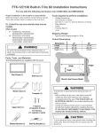
Parts, Tools,
The following
Bracket
and Materials
parts are supplied with the oven:
Base
Cutout
• Do not use a fuse in the neutral or grounding circuit.
Dimensions
Height
Width
16 3/4"
25 1/2"
16 3/4"
25 1/2"
Depth (min.)
23 3/4"
23 3/4"
-leight
Trim Frame
Electric Heat Source Model
Bracket Left
Bracket Bottom
Bracket Top
Template
template
1
2
1" Screw
(1 required, 1 extra)
of this oven:
,120VAC@60Hz
• 13A/1100W
• You need a DEDICATED 120 VAC, 60 Hz, 20A,
fused electrical supply (located in the cabinet
with the microwave as close as possible to the
microwave) serving only the microwave.
• Check with a qualified electrician if you are not
sure whether the oven is properly grounded or if
you do not completely understand the grounding
instructions.
Phillips Screwdriver
Saw (Electric or Hand)
Drill with 7/64" drill bits (Electric or Hand)
Tape Measure
Pencil
Shipping
rating
To avoid risk of electrical shock, personal injury, or
Jeath:
, Before drilling into the wall, note where electrical
outlets are and where electrical wire might be
concealed behind the wall. YOU COULD GET AN
ELECTRICAL SHOCK if you contact electrical
wire with the drill bit.
, Locate and disconnect the power to any electrical
circuits that could be affected by installing this oven.
IFYOU DO NOT DISCONNECTTHE POWER,
IYOU COULD GET AN ELECTRICAL SHOCK_
)ersonal ir
,, Save these instructions for the local electrical
inspectoris use.
• If there is an electrical short circuit, grounding
reduces the risk of electrical shock by providing an
escape wire for the electric current. This appliance is
equipped with a cord having a grounding wire with a
grounding plug.
,, Place the plug into a properly installed and grounded
outlet.
• Amana does not recommend use of an
extension cord.
• Keep the power cord dry and do not pinch or
crush it.
• Do not, under any circumstances, remove the power
supply cord grounding prong!
• This appliance MUST be grounded!
could be exposed to excessive microwave en-
Do not expose yourself to excessive
microwave energy!
• DO NOT try to operate the microwave oven with the
door open.
• DO NOT tamper with or defeat the safety interlocks.
• DO NOT place objects between the microwave oven
front face and the door.
• DO NOT allow soil or cleaner residue to build up on
the flat surfaces around the microwave oven door.
• DO NOT operate the microwave oven if it is damaged.
• The microwave oven door must close properly to
operate safely.
• DO NOT USE THE MICROWAVE OVEN:
,, If the door is bent.
,, If the hinges or latches are broken or loose.
• If the door seals, sealing surfaces or glass is broken.
• DO NOT ATTEMPT TO ADJUST OR REPAIR THE
OVEN YOURSELF!
• It should be adjusted and repaired by a qualified
technician who can check for microwave leakage
after repairing the oven.
)ersonal in
Before you begin installingthe oven, PLACE A PIECE
OF THE CARTON OR OTHER HEAVY MATERIAL (a
blanket) over the countertop or cooktop to protect it.
Do not use a plastic cover. Failure to protect these
Three-prong
(Grounding plug)
Properly polarized
grounding
outlet.
1/2" Screw
(14 required,
1
6 extra)
2
1. "SET"
installment
in Bracket
Base
3. Fixing
'location
screw' in cabinet
5. Installment
of Bracket
Bottom
7. Installment
of Trim Frame
With product, use boxed screw(4 x 20 ram).
Leave the screws protruding from
a minimum
of 3.5 to a maximum
of 4.5
mm
4,5 mmm_
Remove 4 screws from the lower right and left parts
of outer panel, place "SET" in Bracket Base and fix
it by tightening 4 screws again.
2. installment
of Bracket
Left
Fix '1" screw' at the bottom of cabinet with use of
template 1.
4. "SET"
installment
Place Bracket Bottom on Bracket Base like picture
B. Make holes of position A fit to Bracket Base's
and fix screws after making holes with a 7/64 drill or
a #35 drill.
Install "Bracket
screw points.
Bottom" by tightening screws at
6. installment
of Bracket
install Trim Frame to make contact cabinet.
8. installment
of Trim Frame
Top
in cabinet
Fix 2 screws each at the upper and lower parts of
Trim Frmae with the door open.
Fix it by color screw
With template 2, make 2 holes each at the upper
right and left parts of cabinet. (Others for the extra)
Fix "Bracket Top" according to the holes.
Trim Frame Dimensions
(Depth of trim Frame is 7/8")
Assemble the Bracket Left to outer panel.
Push "SET" into the cabinet inside so that the fixed
26 _"
29 34"
bottom screw of cabinet can place in the hole of
Bracket Bottom.
Push "SET" in until the bent part of front Bracket
Base touches the front of cabinet.
f
7//_ f'
27_
,,
i/_ ,,
27" Trim Frame
3
30" Trim Frame
4