1
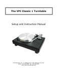
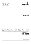
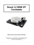
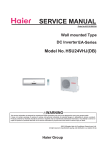
Alesis M-EQ 230
DUAL 1/3 OCTAVE PRECISION EQUALIZATION SYSTEM
USERS MANUAL
A lesis M-EQ 230
DUAL 1/3 OCTAVE PRECISION EQUALIZATION SYSTEM
INTRODUCTION
The A lesis MEQ-230 is a two channel, 30 band/channel, 1/3rd
octave graphic equalizer which features a relay based power-up
delay switching circuit to eliminate turn-on transients in sound
systems.
Each channel features 30 bands of 1/3rd octave equalization with
ANSI and ISO standard center frequencies. Each band is
adjusted by a center detented fader with ±12dB of gain available,
and a master fader controls system gain for that channel. Clip and
signal present LEDs, as well as a bypass switch, are also
provided on each channel.
Inputs and outputs for each channel are via both 1/4" and RCA
jacks. The unit can also be rack mounted in only 1 rack space.
FEATURES
• 2 complete 30 band 1/3 octave equalizers in 1 rack space
• Power up delay circuitry protects speakers by eliminating turn-on
transients
• ±12dB boost or cut per band
• Each channel can be bypassed individually
• Clip and signal present LEDs for each channel
• Inputs and outputs via both 1/4" phone and RCA jacks
Applications
•
•
•
•
•
Feedback control in sound systems
Feedback control in stage monitor systems
Timbre contour of musical instruments
Room voicing
Special sound effects
2
SECTION 1
DESCRIPTION OF CONTROLS
FRONT PANEL
1/3 OCTAVE BAND FADER
Each 1/3rd octave band is controlled by a center detented fader
which provides a boost or cut of 12dB. There are 30 bands per
channel.
MASTER CHANNEL GAIN FADER
Each channel has a Master Gain Fader which controls the
system's input gain by ±12dB.
CHANNEL BYPASS SWITCH
Each channel's EQ can be individually bypassed by means of the
Channel Bypass Switch. The Master Gain Fader affects program
input level only when the channel is not bypassed.
EQ IN LED
The EQ In LED lights when the EQ is in use. The LED will go out
when a channel is bypassed.
CLIP INDICATOR
The red CLIP INDICATOR LED indicates the onset of distortion
(+18 dB). This LED should never light during normal use.
SIGNAL PRESENT LED
The green SIGNAL PRESENT LED indicates that a signal is
currently being fed into the M-EQ 230. This LED lights at
approximately -20dB and should be frequently lit during normal
use.
POWER LED
The POWER button turns the unit on or off.
BACK PANEL
INPUT JACKS (Left & Right)
Accepts instrument to line level input signals for both left and right
channels. Both 1/4" and RCA phono jacks are provided.
OUTPUT JACKS (Left & Right)
Line level output of the M-EQ 230 for both left and right channels.
Both 1/4" and RCA phono jacks are provided.
3
POWER JACK
Accepts the +9VAC power from the M-EQ 230 Power Supply.
This external supply keeps hum, noise, and ground loops to a
minimum.
SECTION 2
SET-UP
INSTRUMENTS, MICROPHONES
The A lesis M-EQ 230 has high impedance inputs that are
ideally suited for use either with instruments or line level signals.
Although microphones can be connected directly into the M-EQ
230 , it is recommended that for quietest operation they be
connected to a mixing console first and then connected to the MEQ 230 as described in Figure 1.
STEREO OPERATION
For stereo operation of the M-EQ 230, connect the left and right
line outputs of the device to be equalized into the left and right
inputs of the M-EQ 230. See Figure 1
FIGURE 1
M-EQ 230 STEREO OPERATION
Alesis 1622
MIXING
CONSOLE
MAIN OUT
LEFT
MAIN OUT
RIGHT
LEFT
INPUT
RIGHT
INPUT
M-EQ
LEFT
OUTPUT
LEFT INPUT
230
RIGHT
OUTPUT
RIGHT INPUT
STEREO
POWER AMP
4
INDEPENDENT USE OF LEFT AND RIGHT CHANNELS
The M-EQ 230 need not be used in a stereo mode since each
channel is completely independent. In Figure 2 , the right
channel is connected to the house sound system for room tuning
while the left channel is connected to the on-stage monitor system
for feedback control.
FIGURE 2
INDEPENDENT USE OF LEFT AND RIGHT CHANNELS
Alesis 1622
MIXING
CONSOLE
AUX SEND OUT
or
MONITOR OUT
MAIN OUT
RIGHT OR LEFT
LEFT
INPUT
RIGHT
INPUT
M-EQ 230
LEFT
OUTPUT
INPUT
RIGHT
OUTPUT
INPUT
MONITOR
POWER AMP
HOUSE
POWER AMP
5
INTERFACING VIA INSERT SENDS AND RETURNS
Another way of interfacing the M-EQ 230 is to connect the unit
directly to the insert send and return patch points (if your console
has them) of the channel that is to be effected. See Figure 3
FIGURE 3
INTERFACING TO A MIXING CONSOLE VIA CHANNEL INSERTS
Alesis 1622
MIXING
CONSOLE
INSERT SEND
RIGHT
INPUT
INSERT RETURN
RIGHT
OUTPUT
M-EQ 230
6
SECTION 3
OPERATION
POWER-UP
When the power is first turned on, the automatic power-up delay
circuit will mute the M-EQ 230 for 2 seconds. This is to prevent
any possible turn-on transient signal from mixers, power amps, or
outboard equipment from possibly damaging speakers.
TO CONTROL FEEDBACK
1 ) Place all microphones in the positions where they will
be used. Set mics to approximate levels.
2 ) Gradually bring up the sound system level until
feedback just begins to occur.
3 ) Feedback will usually occur at two frequencies in each
room; one low and one high. Determine which
frequency is loudest (or that is feeding back first) by
decreasing each slider until one is found that makes the
feedback disappear (see Figure 4A).
4 ) After the feedback frequency is found, gradually
increase the slider until just on the edge of feedback.
5 ) Now gradually decrease the two adjacent sliders until
the feedback again disappears (see Figure 4B).
6 ) Gradually increase the sound system gain until
feedback occurs again.
7 ) Repeat steps 3, 4, and 5.
PLEASE NOTE:
A) In many cases, room acoustics, uneven frequency response
in speaker components and microphones, excessive gain due
to poor microphone technique, poor placement of speaker
systems, or many open microphones in the sound system will
all contribute to feedback which can only be mildly controlled
but not totally eliminated. If excessive EQ is being used it's
best to try to correct some of the reasons for feedback first
before resorting to EQ.
7
B) For feedback control, the sliders of the M-EQ 230 should
always be operated in the downward or cut position.
FIGURE 4
CONTROLLING FEEDBACK
A. Find the 2 major feedback frequencies (1 high, 1 low frequency)
B. Slightly decrease adjacent bands.
A.
B.
ROOM FEEDBACK FREQUENCIES
ADJACENT BANDS SLIGHTLY DECREASED
FOR INSTRUMENT TONAL CONTOURING
1 ) Find the desired frequency band by either referring to
the Frequency Chart (see Figure 5) or by
experimenting.
2 ) Gradually raise the slider of the disired band and the
two adjacent sliders gradually until the desired result is
achieved.
3 ) Repeat as necessary.
If you should find that you are adding large amounts of EQ boost
with more than half of the sliders boosted, then the overall effect is
8
the same as simply raising the volume level. In this case, do the
following:
1 ) With the instrument playing, start by boosting 3 sliders
at a time until the offending frequency area is found. (If
the Clip LED should light, turn down the Input control)
2 ) Now, decrease the sliders until you are cutting the level
instead of boosting.
3 ) Experiment with the amount of decrease of the adjacent
sliders as in feedback control (see Figure 4B).
PLEASE NOTE:
The M-EQ 230 (and all other graphic Equalizers) will sound best when the
sliders show a gradual slope rather than a few wild boosts or cuts (See Figure
4A and 4B).
Since the M-EQ 230 can be used with any electric instrument or
microphone requiring tonal alteration, here are some generic
suggestions as to setup. Since each instrument will sound
different due to the uniqueness of the instrument itself, the type of
music being played, the arrangement, and the touch of the player,
you must use your ears (and the chart below) to ultimately find the
correct settings.
FIGURE 5
KEY FREQUENCIES FOR INSTRUMENTS
INSTRUMENT
KEY FREQUENCIES
Bass Guitar
Attack or pluck is increased at 700 or 1KHz; Bottom added at 60 or 80Hz;
string noise at 2.5KHz
Bass Drum
Slap at 2.5KHz; Bottom at 60 or 80Hz
Snare
Fatness at 240Hz; Crispness at 1 to 2.5KHz; Bottom at 60 or 80Hz
Hi-Hat and Cymbals
Shimmer at 7.5 to 10KHz; Klang or gong sound at about 200Hz
Toms
Attack at 5KHz; Fullness at 240Hz
Floor toms
Attack at 5KHz; Fullness at 80 or 120Hz
Electric Guitar
Body at 240Hz; Clarity at 2.5KHz
Acoustic Guitar
Body at 240Hz; Carity at 2.5KHz; Bottom at 80 or 120Hz
Piano
Bass at 80 or 120Hz; Presence at 2.5 to 5KHz; Crispness at 10KHz;
Honky-tonk sound at 2.5KHz as bandwidth is narrowed; Resonance at
40 to 60Hz
Horns
Fullness at 120 or 240Hz; Shrill at 7.5 or 5KHz
9
Voice
Fullness at 120Hz; Boominess at 200 to 240Hz; Presence at 5KHz;
Sibilance at 7.5KHz; Air at 12 to 15KHz
Harmonica
Fat at 240Hz, bite at 3-5kHz
Conga
Resonant ring at 200 to 240Hz; Presence and slap at 5KHz
Whether used to alter the timbre of an instrument, control
feedback, or improve speech intelligibility, it's important to know
what effect each portion of the frequency spectrum has on the
sound.
In summary, the frequency spectrum can be divided up into six
important sections.
FIGURE 6
AUDIO OCTAVE RANGES
FREQUENCY RANGE
16Hz to 60Hz
60Hz to 250Hz
250Hz to 2000Hz
WHEN USED PRODUCES
THIS EFFECT
sense of power,
felt more than heard
Fundamentals of rhythm
section, EQing can change
musical balance making it
fat or thin
Low order harmonics of
most musical instruments
2KHz to 4KHz
Speech Recognition
4KHz to 6KHz
Clarity and definition of
voices and instruments,
makes music seem closer to
listener, adding 6dB at 5KHz
makes entire mix seem 3dB
louder
Brilliance and clarity of sounds
6KHz to 16KHz
WHEN USED TOO MUCH
PRODUCES THIS EFFECT
makes music muddy
makes music boomy
telephone quality to music
500 to 1KHz horn-like,
1K to 2KHz tinny,
listening fatigue
3KHz listening fatigue,
lisping quality, "m", "v",
"b" indistiguishable
sibilance on vocals
sibilance, harshness on vocals
As with any signal processor, the M-EQ 230 should be used with
discretion since too much of a good thing can make the sound
worse instead of better. Although it is a wonderful device and will
help your sound a lot, remember that a little goes a long way.
If you're using the M-EQ 230 for tonal contour of an instrument or
voice, Figure 5 will help you zero in on the key frequencies of
some popular instruments.
Remember: The chart serves only as a starting point.
you must use your ears as a guide.
10
Ultimately,
SECTION 4
SPECIFICATIONS
ELECTRICAL CHARACTERISTICS
FREQUENCY RESPONSE
25Hz to 20kHz in 1/3 octave increments
HARMONIC DISTORTION
.004% @ 1KHz @ 0dBV
NUMBER OF CHANNELS
NOMINAL LEVEL
MAXIMUM LEVEL
IMPEDANCE
2
0dBV
+18dBV
1MΩ
OUTPUT
NUMBER OF CHANNELS
MAXIMUM LEVEL
IMPEDANCE
2
+18dBV
240Ω
INPUT
FRONT PANEL
CONTROLS
INDICATORS
SWITCHES
REAR PANEL
JACKS
POWER
30 Band, 1/3rd octave , ±12dB, center frequencies set to ANSI and
ISO standards.
Power, Signal Present, Clip and In/Out LEDs per channel
In/Out
Input Left and Right - 1/4" and RCA
Output Left and Right - 1/4" and RCA
Power - Barrel Jack
REQUIREMENTS
9 Volts AC, 7.5 Volt Amps external transformer, UL approved.
DIMENSIONS (W x H x D)
19" x 1.75" x 4"
WEIGHT
2.5 lbs.