1
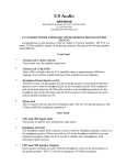
AESDA
PORTABLE AES TO ANALOG CONVERTER
Theory of Operation
The AESDA was designed to provide a portable means of converting an AES-3 or S/PDIF
digital audio stream into a professional high-quality two-channel analog audio output. The
digital input is extensively screened at receiving, with faults in the data or transport
annunciated by type. A dual 11-segment VU meter monitors the audio level from the DAC
or the level at the output. In the interest of conserving battery power, two display modes
are available on the VU meter. One is a bar graph of the signal level, the other is a single
LED which indicates the peak instantaneous signal level, with the single LED consuming
less power than the bar graph. A ten-segment red LED bar serves to indicate the various
operating modes and detected faults, if any. A switch selects the function of this LED bar,
either to indicate operating mode, detected sample rate, etc., or to display any detected
fault. The analog output has separate level controls for the left (A) and right (B) side.
Output level may be set by selecting the analog output on the VU meters, and setting the
controls to the desired value. A headphone monitor jack with separate level control is also
provided for checking the analog audio signal. Recommended headphone impedance is
between 16 and 100 Ohms. This jack can also be used as an unbalanced line level output.
Primary power for the unit can be sourced from four “AA” cells (Alkaline, Lithium-Ion or
Nickel-Metal-Hydride cells are recommended). An external coaxial power jack (5.5mm x
2.1mm) is provided for situations where battery power may not provide an adequate
length of operation. The external power source should be able to provide 12 Watts of
power at a Voltage range from 3.5VDC to 15VDC. This allows the AESDA to operate on a
wide variety of power sources including car batteries, portable camera batteries, or a “wall
wart” type of power supply.
Digital Monitor LED Function Details
Digital Info Indicators
The Whirlwind AESDA is a portable device for converting AES-3 and
S/PDIF digital audio signals into analog audio signals. Digital input to
the AESDA is through the female XLR or BNC. There are level meters
that display the level of the incoming digital signal or they can be
switched to display the analog output signal level. Each of the two
decoded analog audio outputs has an independent level control, from
which the signal is sent to the analog metering circuits and male XLR
outputs. Another unbalanced analog output is provided on a 3.5 mm
TRS jack, with its own level control, for use with headphones or as an
unbalanced line level driver. Both professional and consumer
versions of AES-3 can be decoded by the AESDA.
Additionally, the AESDA provides diagnostic analysis of the incoming
AES-3 and S/PDIF digital signals for help in troubleshooting signal
faults. The digital monitor section identifies the sample rate and
characteristics of the incoming digital signal, and if there is a problem
in the digital audio stream several different fault types can be
identified.
99 Ling Road . Rochester, NY 14612
Phone 585 663-8820 . Fax 585 865-8930
Email: [email protected]
http://www.whirlwindusa.com
Sample Rate
There are six sample rate indicators that show the closest standard sample rate to
the signal as received: 44.1kHz, 48kHz, 88.2kHz, 96kHz, 176.4kHz, and 192kHz.
Signals that have sample rates lower than 44.1kHz may be locked to and decoded
by the AESDA, but their sample rate will not be displayed. Only one sample rate
LED should be illuminated at one time in normal operation. With no input signal, the
Fault LED and the No Lock LED (in Fault Type mode) will be illuminated instead.
Audio
The Audio LED indicator illuminates when the input digital data stream has been
determined to be Pulse-Code Modulated (or PCM) digital audio. For other digital
inputs that are not PCM audio, such as TDM data to DTS-CD, this indicator will be
off.
Consumer
The Consumer LED indicator illuminates when the Pro/Consumer mode bit in the
digital audio stream's Status bit indicates Consumer mode, and is off in Professional
mode. Note that this indicator only presents validly when the AESDA is locked to a
valid PCM audio data stream.
Pre-Emph(asis)
The Pre-Emph(asis) LED Indicator illuminates when the digital audio stream's
Status bit field for this condition indicates that it is present. Typically, pre-emphasis
is only used for sample rates of 32kHz, 44.1kHz, and 48kHz. When the indicator is
off, it indicates that the audio signal embedded in the digital stream has not been
pre-emphasized.
Fault
The Fault LED indicator illuminates when a detected fault, either in the hardware or
the digital input signal has been detected. The user then can switch the unit over to
the Fault Type display to further identify the fault.
Fault Type indicators
Hardware Fault
The Hardware Fault LED Indicator is illuminated if anything in the power-on
diagnostic tests did not pass, or if the information presented by the control switches
is invalid or cannot be interpreted. The unit may not operate properly with this LED
illuminated.
No Lock
The No Lock LED Indicator illuminates if no signal is present on either of the two
digital input connectors, or if the signal cannot be interpreted. Application of a valid
digital audio stream to either digital input will cause this indicator to extinguish.
Parity Error
The Parity Error LED Indicator illuminates when the incoming data did not have an
even number of ones and zeros, or if the number of bits was not 32. Typically, parity
and bit-length errors are indicative of weak or noisy signals. Parity and bit errors are
also typically not consistent between fields of data, so flickering of this LED is not
uncommon in the presence of these types of errors.
CRC Error
The CRC Error LED Indicator illuminates when an AES Professional Data Block
Cyclical Redundancy Check did not pass. When generated, the data is passed
through a CRC generator, which calculates and embeds an 8-bit check word at the
end of each frame. The digital receiver in the AESDA recalculates this CRC number
from the received data and compares its result to the CRC number received. If the
two do not match, then the data was not received the same way that it was
transmitted, i.e., there may be one or more data bits that are in error. Note that
Consumer Mode AES-3 and S/PDIF do not use CRC checking, so this LED will be
off when receiving audio data of this type.
Confidence Flag
The Confidence Flag LED Indicator illuminates if excessive distortion is detected in
the digital signal received. The distortion may be from low signal level, excess or
incorrect cable impedance, or asymmetry in the signal (the “1” part and the “0” part of
the signal not of equal length within a specific percentage). If only this error exists,
without Parity, CRC, or No Lock errors, it is indicative of a signal that is marginally
useable, and probably not reliable in the long run. When other signal-type errors are
present, this is indicative of a bad cable, too long of a cable run, a bad transmitter, or
an excessively noisy environment.
Validity Bit
The Validity Bit LED Indicator illuminates when the Left or Right or both of the Validity
Bits indicate invalid data. These bits are embedded in the audio data, and there is
one validity bit in each subframe. When one channel is invalid, the Validity Bit LED
will flicker; if both channels indicate invalid, the LED will be steadily on.
No Error
The No Error LED Indicator is illuminated when no detected error is present. This
provision allows at least one LED to be illuminated when Fault Type mode is entered
and there are no faults.
Over Temp
The Over Temp LED Indicator illuminates if the detected temperature inside the unit
exceeds 85°C. This temperature is the upper limit for reliable operation of the
various internal components, and if exceeded for a long period of time, could cause
permanent damage to the AESDA. No shutdown action is instigated by the AESDA,
it just serves as a warning to the user.
Warranty
This product is guaranteed for one year from the date of purchase against manufacturing defects. For warranty service, return the
unit, along with the original sales receipt, to: whirlwind, 99 Ling Road, Rochester, NY 14612, postage prepaid. We will repair or
replace the unit at our option and pay the return postage.
7. The Power LED is illuminated when the Power switch is ON. It will dim as the
batteries lose power, thus giving an indication of remaining battery life.
DIGITAL MONITOR
48 kHz
88.2 kHz
96 kHz
12
NO LOCK
PORTABLE AES TO ANALOG CONVERTER
PARITY ERROR
LEVEL METERS
CRC ERROR
A
176.4 kHz
192 kHz
AUDIO
11
AESDA
HARDWARE FAULT
CONSUMER
VALIDITY BIT
OVER TEMP
FAULT
PHONES VOL
-6
-3
0
+12 +15 CLIP
7
OUTPUT LEVEL
SOURCE MODE
POWER
DIGITAL
INFO
D. INPUT
DOT
A. OUTPUT
BAR
CHANNEL A
CHANNEL B
9. The Digital Monitor Select switch selects whether “Digital Info” (digital signal
parameters) or “Fault Type” information is displayed on the vertical tensegment Digital Monitor LED array.
2
dBfs
dBV
B
METERS
FAULT
TYPE
PHONES
-9
+9
NO ERROR
PRE-EMPH
10
-45 -33 -27 -21 -18 -15 -12
-3
0
+3 +6
-27 -15 -9
1
CHANNEL A
44.1 kHz
ANALOG OUTPUTS
6VDC
8. The Power Switch applies power from the external supply or the batteries.
When power is applied, the AESDA runs internal diagnostics, culminating in an
LED display test where the 32 LEDs in the three displays are illuminated in
sequence, then extinguished in the same manner. The unit then goes into its
normal operating mode.
10. Phones Out Jack provides a high-quality analog version of any digital audio
source received by the AESDA. Peak output level is +4dB, and the output is
capable of driving headphones from 16 to 100 Ohms impedance. It can also be
used to feed an unbalanced line input. The left channel (A) is connected to the
tip, the right (B) to the ring, and the sleeve to common of the unbalanced
3.5mm TRS jack.
3
CHANNEL B
18
13
AES/EBU INPUTS
14
11. Phones Vol(ume) Control adjusts the analog audio level present on the
Phones output (3.5mm) TRS jack. The setting of this control has no effect on
the Analog Outputs or the meters.
MADE IN USA
9
8
6
Controls and Functions
1. AES/EBU Input Connectors are provided for Digital Audio input. The
BNC connector provides an input for 75 Ohm unbalanced S/PDIF
audio, and the female XLR provides an input for 110 Ohm balanced
AES/EBU audio. Both inputs are transformer and DC isolated (up to
50V), and accept AES/EBU and S/PDIF signal levels ranging between
5V p-p and 250mV p-p.
2. VU Meters, two eleven segment LED arrays, can display either the
digital input level or the analog output level. The first ten LEDs are
green; the eleventh is red. Two measurement scales are provided, one
for the digital input, which is in dB Full-Scale, or dBfs units, with the red
LEDs illuminating at a point about 1 to 2dB less than the maximum
output of the Digital-to-Analog converter, and one for the analog
outputs. This is measured in dBV, where 1V RMS of output equals
0dBV, with the red LEDs illuminating for an output level of +18dBV.
99 Ling Road . Rochester, NY 14612
Phone 585 663-8820 . Fax 585 865-8930
Email: [email protected]
http://www.whirlwindusa.com
5
4
3. Analog Output Jacks are balanced male XLR connectors, capable of driving
loads from 600 Ohms to near infinity at output levels of up to +27dBV, although
the outputs are metered only to +18dBV. Output noise is less than -95dB. Total
harmonic distortion is less than 0.004% at 0dBV of output, and less than 0.01%
at +18dBV of output. Frequency response is flat to within 0.2dB from 22Hz to
20kHz. Each output has its own independent level control, which, along with
the VU meters, allows precise setting of signal level for each channel. Pin 1 is
signal ground, pin 2 is positive, pin 3 is negative, and the shell is case ground.
4. Output Level Controls independently control the level presented at the
analog outputs. The level of each output may be monitored on the VU meters
by selecting Analog Output with the Meter Source Select switch.
5. The Meter Mode Select switch controls how the VU Meter information is
displayed. In “DOT” mode the VU display will illuminate the LED that most
corresponds to the output level at that instant. In “BAR” mode, the VU display
operates as a conventional bar-graph LED display. The dot mode conserves
power allowing longer operation under battery power.
6. The (VU) Meter Source Select switch controls whether the level of the Digital
Input or the Analog Outputs are selected for monitoring on the VU Meters. In
the “D(igital) Input” position, the Analog level of the decoded Digital Input is
displayed. In the “A(nalog) Output” position, the level present at the Analog
Outputs XLR Connectors after the Output Level controls is displayed.
12. The Battery Compartment is a slide out drawer that accepts four “AA” size
cells. Either alkaline cells or externally-rechargeable Nickel-Metal-Hydride
(NiMH) or Lithium-Ion cells may also be used. Battery life is highly dependent
upon several factors, including load impedance, output level, the use of
headphones, and the mode of the level meters. Typical loading will provide
about four hours of operation with fresh batteries. The AESDA does not have
internal battery recharge capability.
13. The 6VDC external power jack is a 5.5mm x 2.1mm size with the center
contact wired positive and the barrel contact negative. When a plug is inserted
into this connector, the internal batteries are disconnected. A 6VDC 2.5A plugin power supply is supplied with the unit. Input voltage can be anywhere from
4.8VDC to 15VDC, provided the power source can deliver at least 12 Watts
peak. This wide input range allows the AESDA to be powered from lantern
batteries, auto batteries, and camera batteries, as well as the familiar AC “wall
wart” plug-in power supplies
14. The Digital Monitor ten-segment LED array displays operational status
and fault diagnostics. The type of information shown on this display is
controlled by the Digital Monitor Select switch. In the “Digital Info” position, the
display shows the detected sample rate, the type of data present, if the data is
consumer or professional mode audio (if an audio stream is detected), if preemphasis is enabled, and if a fault is present. In the “Fault Type” position, it will
indicate the type of fault(s) present, if any, and also if no fault is detected. The
types of faults annunciated are Hardware (internal diagnostics), No Lock (or no
signal present), Parity or Bit Length error, CRC error (if the audio data present
is in Professional mode), Signal Confidence (wave shape, level or symmetry is
borderline or out-of-tolerance), Validity Bit not present, Over Temperature, and
No Fault Detected.