1
Agilent E6432A
VXI Microwave Synthesizer
Product Note
An Introduction to the
Agilent E6432A plug&play Driver
A4032A
POWER
On
Standby
High performance microwave
capability in VXI
●
10 MHz to 20 GHz
●
–90 dBm to +20 dBm
●
< 400 µs frequency switching time
●
1 Hz frequency resolution
●
AM, FM and Pulse modulators
●
VXI plug&play driver
Introduction
Programming Environments
VXI Interfacing
Today’s VXI instruments communicate
with application programs through
plug&play drivers. In some cases,
these drivers are just one way to
communicate. For the E6432A
microwave synthesizer, its plug&play
driver is the only means of communication with the host controller or its
application programs.
To support the E6432A plug&play
driver, the operating system foundation required by the host controller is
Microsoft Windows NT® 4.0, with
Service Pack 3 or above installed.
Other operating systems, such as
Windows 95/98, UNIX®, or MacOS
are not supported at introduction.
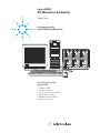
There are several interfacing choices
available from host controller to VXI
instruments. Three of these are supported by the E6432A plug&play
driver. They are:
This product note provides an
overview of the communication
process, the range of hardware and
software configurations supported,
and an introduction to the features
of the instrument made available
through the plug&play driver.
The E6432A microwave synthesizer
is a register-based device, rather
than a message-based device. There
are two reasons for this. First, the
E6432A is designed to be a system
source rather than a bench source, so
its user interface and command set
are simple and straightforward. A
register-based design supports this
application. Secondly, the E6432A
employs a fast-switching architecture
in both frequency and amplitude
switching. Switching times of less
than 400 µs can be achieved in real
customer applications only if the
E6432A processing time is kept to
well under 50 µs. This can only be
accomplished with a register-based
design.
Most modern automated test systems
use programming environments
and VXI interfaces that support the
plug&play driver architecture. These
systems will easily integrate the
E6432A. For systems using older,
legacy software and VXI interfaces,
support for the E6432A may require
rewriting and/or changing interfaces.
These conditions will be covered in
this note.
Application programs running on
Windows NT that are compatible
with the E6432A plug&play driver
are:
●
HP VEE 4.0 or higher
●
National Instruments LabView and
LabWindows/CVI versions 4.0
or higher
●
Microsoft Visual Basic
version 5.0 or higher
●
Microsoft Visual C/C++
versions 5.0 or higher
Application programs such as
Agilent Basic for Windows have no
provision for communicating with
plug&play drivers and are therefore
not supported.
●
VXI Embedded Control (for example, E6234A running Windows NT)
●
National Instruments VXI-MXI-2
●
IEEE-1394 ("Firewire")
(for example, E8491A)
The remaining VXI interfaces
(HP and National Instruments
GPIB-VXI, and National Instruments
MXI-1) are unsupported.
The VXI data specification for the
E6432A is A16/A24, D16/D32. Due to
the large size of frequency registers,
floating point arithmetic is a must.
The interface must be capable of
allocating a large block size of A24
address space (256k). GPIB interfaces are unsupported because they
are fundamentally message-based
interfaces. They are not designed to
communicate with register-based
instruments without special, proprietary software that must be written
and downloaded into their memories
prior to using the plug&play driver.
Microsoft, Windows and Windows NT are U.S. registered
trademarks of Microsoft Corporation.
UNIX is a registered trademark of the Open Group.
2
National Instruments has two versions of the MXI interface that are
usable in a host controller. The older
VXI-MXI-1 slot 0 controller and its
host card (the AT-MXI interface) do
not operate correctly with E6432A,
due to the AT-MXI interface’s inability to access more than 64k of A24
address space. (Remember, a minimum of 256k is required.) The
newer MXI interface from National
Instruments (the VXI-MXI-2 interface) and its host controller card
(the PCI-MXI interface) work
properly with all of the application
programs listed.
A new serial interface for VXI based
on IEEE-1394 is available from
Agilent (the E8491A). This interface
has nearly the same performance as
MXI-2 in many applications. The
E8491A is supported for use with
the E6432A.
Embedded controllers are available
from both Agilent and National
Instruments. Those controllers that
contain the Intel Pentium® processor
and run Microsoft Windows NT 4.0
are supported for use with the
E6432A.
Initializing the Instrument
After installing the interfaces and
drivers using the procedures given in
the user documentation, it is time to
apply power to the VXI mainframe
and check out the system.
Register-based devices typically
do not contain a processor and
firmware that perform bootstrap and
self-test functions at power on. These
functions are jointly executed by the
host controller and the device. For
the E6432A, the functions are performed when the host controller
issues the ViInitialize function call
through the plug&play driver. When
power is first applied to the E6432A,
the red FAIL LED is lit. This LED
remains lit until a successful
completion of the ViInitialize
function call. Within this function
call are commands that:
●
issue the bootstrap commands
to initialize the onboard assist
processor
●
perform a comprehensive
digital self-test
●
perform a limited analog self-test
●
preset the instrument to
a known state
●
query the error buffers for
any error conditions
●
issue the command to extinguish
the red FAIL LED after a
successful completion
In the programming examples shown
later, we will show that in VEE,
the ViInitialize function call is sent
automatically at the first call to
the instrument. In NI LabView, the
ViInitialize function call must be
sent explicitly as the first call to
the instrument.
The Soft Front Panel
All functions of the E6432A are
represented in the soft front panel
(SFP). The online help system documents the SFP and the plug&play
driver completely. The E6432A SFP
is accessed through the Start menus
of Windows NT. If no VXI interface
is installed on the computer, or the
hardware is not present, the SFP
may be run in Demo Mode as a
learning and demonstration tool.
The online help system will be
fully functional.
Pentium is a U.S. registered trademark of Intel Corporation.
3
Features of the plug&play Driver
Driver functions are divided into
these major categories:
●
Initializing the instrument
Table 1
Set RF Output (On/Off)
HPE6432_SetRfOutputState
Get RF Output (On/Off)
HPE6432_GetRfOutputState
Set Freq, ALC, Atten, Bit
HPE6432_SetFreqAlcAttenBit
Set Freq, ALC, Atten
HPE6432_SetFreqAlcAtten
Get Freq, ALC, Atten
HPE6432_GetFreqAlcAtten
Selecting and enabling
modulation types
Set Frequency
HPE6432_SetFrequency
Set ALC, Atten
HPE6432_SetAlcAtten
Selecting and enabling
trigger modes
Set Output Power
HPE6432_SetOutputPower
Power Search
HPE6432_PowerSearch
●
Selecting operation modes
Set Reference Source (Int/Ext)
HPE6432_SetRefSource
●
Managing the list
Get Reference Source (Int/Ext)
HPE6432_GetRefSource
Querying status and errors
Set Dwell Time
HPE6432_SetDwellTime
●
●
●
●
Setting and enabling frequency
and power
Table 1 is a list of instrument
functions available for setting
output functions.
List Modes, Trigger Modes and
Markers
The E6432A plug&play driver
includes a comprehensive online
help system, with complete
documentation that should be used
as the primary reference source for
the instrument. All aspects of using
and programming the E6432A and
the SFP are fully documented. The
help system may be installed and
run on a separate computer without
other modules of the plug&play
driver installed.
4
Get Dwell Time
HPE6432_GetDwellTime
Set Settling Time
HPE6432_SetSettlingTime
Get Settling Time
HPE6432_GetSettlingTime
In many instances, the systems
programmer has a predefined list
of test frequencies, amplitudes, and
marker events that are defined by the
needs of the test program. Often, signal sources and measuring receivers
must be coordinated to be at the
same test frequencies simultaneously
to make measurements. Users want
to minimize system time between
measurements, since performing
precision measurements can be
time consuming.
To assist the programmer with
efficient synchronization between
signal source and measuring receiver,
the E6432A implements a list mode
that holds up to 128k list entries.
Each entry may hold a frequency
value, an ALC value, an attenuator
value, and a mode byte that sets
various conditions at that entry
point. For example, the mode byte
has bits for enabling or disabling RF
blanking at that entry point, putting
out a sync marker at that entry, or
enabling long blanking to provide
extra settling time at that entry.
To make the most of this list mode,
comprehensive triggering is available
for executing the list entries in the
most useful way for the test program.
Input triggering can be from the front
panel SMB connector, over the VXI
TTL backplane triggers, VXI0-VXI7,
or manually via the SFP. Any one
of the backplane triggers can be
assigned to Trigger In. The Trigger
Out, or settled marker, is a synchronization signal that can be used as a
data-ready flag, a trigger to a measuring receiver, or a timing signal for
the host controller. It is always available at the front panel. Any one of
the VXI backplane triggers can be
assigned to Trigger Out.
Table 2
Sync In is a reset trigger. It may be
set to abort a list and reset the list
pointer to the beginning of list memory. It may be used to run a list. It
may be disabled. Any one of the VXI
backplane triggers may be assigned
to Sync In. Sync Out is the programmable marker. Any entry in the list
mode may enable the Sync Out marker. If enabled, it will coincide with
the Trigger Out, or settled marker,
for that list entry. Any one of the VXI
backplane triggers may be assigned
to Sync Out.
Long blanking
Table 2 summarizes the trigger,
marker, and blanking modes.
Trigger In
Automatic (default)
Trigger In disabled
trigger once
wait for trigger, then run list once
triggered
wait for trigger to advance to next list entry
auto (default)
Sync In disabled
wait
wait for sync to start list
restart
abort list and restart from beginning
Trigger Out
Sync In
Sync Out
settled marker - always enabled
wait for start/restart
combines wait for start and abort/restart
disabled (default)
list entry does not generate sync marker on
settled (Trigger Out still enabled)
enabled
list entry generates sync marker on settled
(and Trigger Out marker)
enabled (default)
blank RF while tuning (minimum 270 µs
settling time on frequency changes)
Repeat
Blanking
run list continuously until aborted
disabled
do not blank RF while tuning
disabled (default)
frequency settled to within 50 kHz when
Trigger Out edge occurs
enabled
RF blanking extended to 350 µs. Frequency
settled to noise level when Trigger Out edge
occurs.
Attenuator switch
An example function call to download an array of list entry points is:
ViSTATUS HPE6432_WriteListPoints
(ViSession instrumentHandle,
ViUInt32 startingPoint ViReal64
Frequency[], ViReal64 ALC_value[],
ViInt16 Attenuator[], ViInt16
featureBits[], ViInt16 alcOffset[],
ViUInt32 numberOfPoints);
blanking always extended to 20 ms
Once downloaded, the list is executed by calling Hpe6432_run_list().
Depending on the trigger mode set,
the list is run all the way through,
repeated until aborted, or executed
one entry per input trigger.
5
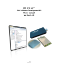
Programming Examples
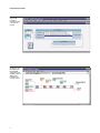
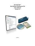
Figure 1
A typical VEE
program for
controlling a signal
source in a test
program.
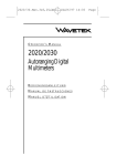
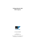
Figure 2
A LabView program
that initializes the
Agilent E6432A,
sets frequency and
amplitude, enables or
disables pulse
modulation, and
closes the session.
6
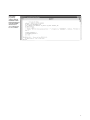
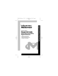
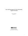
Figure
A Visual Basic
programming
example calling the
initialization routine.
Note that all functions
return VI_SUCCESS,
which is zero for
success and non-zero
for error conditions.
7
Warranty Information
All Agilent products described in
this document are warranted against
defects in material and workmanship
for a period of one year from date of
shipment.
Related Agilent Literature
Creating Frequency Lists
Using a Spreadsheet and
ActiveX Product Note
literature number 5968-8434E
E6432A Configuration Guide
literature number 5967-6272E
E6432A Product Overview
literature number 5967-6178E
E6432A Technical Specifications
literature number 5968-1242E
High Performance Microwave
Capability in VXI Brochure
literature number 5967-6313E
Test Systems and
VXI Products Catalog
literature number 5980-0307E
Visit our websites:
Agilent Aerospace and Defense
Information —
www.agilent.com/find/defense_ATE
Agilent Signal Sources Information —
www.agilent.com/find/signal_sources
Agilent VXI Product Information —
www.agilent.com/find/vxi
Agilent Technologies' Test and Measurement
Support, Services, and Assistance
Agilent Technologies aims to maximize the
value you receive, while minimizing your risk and
problems. We strive to ensure that you get the test
and measurement capabilities you paid for and
obtain the support you need. Our extensive support
resources and services can help you choose the
right Agilent products for your applications and
apply them successfully. Every instrument and
system we sell has a global warranty. Support is
available for at least five years beyond the production life of the product. Two concepts underlie
Agilent's overall support policy: "Our Promise"
and "Your Advantage."
Our Promise
Our Promise means your Agilent test and
measurement equipment will meet its advertised
performance and functionality. When you are
choosing new equipment, we will help you with
product information, including realistic performance
specifications and practical recommendations from
experienced test engineers. When you use Agilent
equipment, we can verify that it works properly, help
with product operation, and provide basic measurement assistance for the use of specified capabilities, at no extra cost upon request. Many self-help
tools are available.
Your Advantage
Your Advantage means that Agilent offers a wide
range of additional expert test and measurement
services, which you can purchase according to
your unique technical and business needs. Solve
problems efficiently and gain a competitive edge
by contracting with us for calibration, extra-cost
upgrades, out-of-warranty repairs, and on-site
education and training, as well as design, system
integration, project management, and other professional engineering services. Experienced Agilent
engineers and technicians worldwide can help
you maximize your productivity, optimize the return
on investment of your Agilent instruments and
systems, and obtain dependable measurement
accuracy for the life of those products.
By internet, phone, or fax, get assistance
with all your test & measurement needs
Online assistance:
www.agilent.com/find/assist
Phone or Fax
United States:
(tel) 1 800 452 4844
Latin America:
(tel) (305) 269 7500
(fax) (305) 269 7599
Canada:
(tel) 1 877 894 4414
(fax) (905) 282 6495
Australia:
(tel) 1 800 629 485
(fax) (61 3) 9210 5947
Europe:
(tel) (31 20) 547 2323
(fax) (31 20) 547 2390
New Zealand:
(tel) 0 800 738 378
(fax) 64 4 495 8950
Japan:
(tel) (81) 426 56 7832
(fax) (81) 426 56 7840
Asia Pacific:
(tel) (852) 3197 7777
(fax) (852) 2506 9284
Product specifications and descriptions in this
document subject to change without notice.
Copyright © 1999, 2001 Agilent Technologies
Printed in U.S.A. March 26, 2001
5968-3660E