1
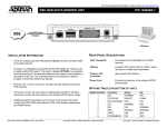
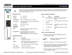
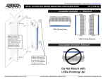
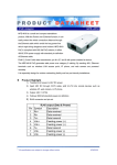
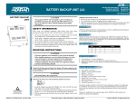
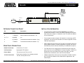
For more detailed documentation, visit us online at www.adtran.com TSU ACE P/N 1200295L1 NETWORK NETWORK T1 Network OFF V.35 NX56/64 INSTALLATION INFORMATION NETWORK CONNECTION PINOUT Pin Name Description 1 R1 RXDATA Receive data from the Network - Ring 2 T1 RXDATA Receive data from the Network - Tip 3, 6, 7, 8 UNUSED n/a 4 R TXDATA Transmit data towards the Network - Ring 5 T TXDATA Transmit data towards the Network - Tip • An eight-position modular jack (labeled NETWORK) is provided to connect to the network T1 circuit. The pinout is provided on this Quick Start Guide. See Chapter 2, Installation, of the TSU ACE User Manual for more information. • The rear panel contains a single V.35 interface for connecting to DTE equipment. The pinout for this interface is located in Appendix C of the TSU ACE User Manual. • When shipped from the factory, the TSU ACE is uninitialized and set to factory default conditions. At the first application of power, the unit will automatically execute self-tests followed by an initialization sequence. • The TSU ACE can be configured and controlled using the local front panel of the unit or from ADTRAN’s PC Control Program, T-WATCH. A limited menu tree is provided on the back of this sheet. For more detailed menu information, refer to the TSU User Manual. • Additional information can be found on the product CD which contains the TSU ACE User Manual, FAQs, Data Sheets, Applications, and White Papers. REAR PANEL DESCRIPTIONS Network Connector Connection to T1 circuit V.35 Connector High-speed DTE interface Power Switch Turns power to the TSU on or off 115 VAC Connection Power cord connection for a reliably grounded 115 VAC, 60 Hz power source Quick Start Guide, 61200295L1-13A, September 2001 ON 115VAC/60HZ .15A Technical Support 1-888-4ADTRAN (1-888-423-8726) Copyright 2001 ADTRAN, All Rights Reserved TSU ACE P/N 1200295L1 MENU TREE - OVERVIEW 1) NI PERF REPORTS 1) STATUS 2) CURR ERR/ALM 3) ERR/ALM HISTORY 2) CONFIG 1) NETWORK (NI) MAIN MENU 2) PORT 1) TIME/DATE 2) SOFTWARE REV 3) UTIL Displays the current software revision 3) REINIT UNIT 4) ADDRESS 5) SET PASSCODE 6) KEYPAD 7) FACTORY RESTORE Returns all configurations to factory settings 1) NETWORK TESTS 4) TEST 2) RUN SELF-TEST 3) PORT TESTS Quick Start Guide, 61200295L1-13A, September 2001 Technical Support 1-888-4ADTRAN (1-888-423-8726) Copyright 2001 ADTRAN, All Rights Reserved