Transcript
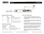
For more detailed documentation, visit us online at www.adtran.com DSU 56/64 DATA SERVICE UNIT REAR PANEL DESCRIPTIONS INSTALLATION INFORMATION • The 8-pin modular jack (RJ-48S) labeled TELCO connects the DSU 56/64 to the DDS network. • All setup or configuration parameters for the DSU 56/64 are selected with an eight position DIP switch. This switch, labeled OPTIONS, is accessible from the rear panel. The label also references the options chart located on the bottom of the unit. The individual options are explained in detail in Chapter 2 of the DSU 56/64 User Manual. • Primary V.35, a 34-pin connector, provides the high speed synchronous DTE interface. • The power cord on the rear panel is mechanically secured to the back panel and provides the connections to the integral AC/DC power supply. • Additional specific information can be found on the product CD which contains the DSU 56/64 User Manual, FAQs, Data Sheets, Applications, and White Papers. Quick Start Guide, 61200062L1-13A, June 2001 P/N 1200062L1 Telco Connector Connection to the dedicated circuit (DDS network) Options 8-position DIP switch which is used to select all setup or configuration parameters Primary V.35 Connector High speed DTE interface Power Cord Provides connections to the integral AC/DC power supply OPTIONS TABLE (ON BOTTOM OF UNIT) Switch Position 1 2 3 4 5 6 7 8 Technical Support 1-888-4ADTRAN (1-888-423-8726) Function CS CS DELAY ANTI-STREAM CD SR RDL RATE SCRAMBLER Down NORMAL SHORT OFF NORMAL ON ENABLE 56k ON Up ON LONG ON ON NORMAL DISABLE 64k OFF Copyright 2001 ADTRAN, All Rights Reserved