1
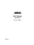
TRACER Monitored Protection Switch (MPS)
Quick Start Guide
61280300L1-13B
October 2003
About this Quick Start Guide...
This guide contains information for installing your TRACER MPS system. ADTRAN recommends that the entire TRACER link be tested on a
lab bench prior to installation in the field.
Verify the existence of an adequate microwave path for each hop or link to ensure that a point-to-point microwave system is feasible for your
particular application. Record the frequency of your microwave system (2.4 GHz or 5.8 GHz) and be sure to configure the Frequency Band
menu option appropriately before operating your TRACER MPS. For more details, refer to Reviewing the Menus on page 4.
Before you begin...
Required Components
•
(2) TRACER Baseband Processor (BBP) and RF Converter (RFC) rackmount units
Or,
•
•
•
•
•
•
•
•
•
•
(2) TRACER 4103 or 4203 integrated rackmount radio units
RS-232 interface cable and VT100 terminal (or a PC with VT100 emulator software) for connecting to the unit
(2) RS-232 (MALE) to RJ-45 (FEMALE) adapter (ADTRAN P/N 3196ADPT010) for creating the VT100 management chain (included in
the TRACER MPS shipment)
(2) 8-conductor RJ-45 to RJ-45 straight-through cable for creating the VT100 management chain (included in the TRACER MPS
shipment)
(4) Straight-through T1 cables to connect the TRACER BBP or 4103/4203 T1 interfaces to the MPS (2 are included in each TRACER
shipment)
(2) N-Type (MALE) to SMA (MALE) cables for connecting the antenna interfaces (TRACER units) to the TRACER MPS (included in the
TRACER MPS shipment)
18, 20, or 22 AWG dual-conductor cable for connecting the alarm contacts between the TRACER BBP or 4103/4203 and the TRACER
MPS; also needed for connecting the MPS to an external alarm monitoring system
Antenna, mounting hardware, and feedline cable
21 to 63 VDC power source (available from ADTRAN)
(2) Straight-through T1cables to connect the TRACER MPS to other CPE equipment (included in the TRACER MPS shipment)
Or,
•
(2) T1 crossover cables to connect the TRACER MPS T1 interfaces to the public-switched network (included in the TRACER MPS
shipment)
1
1
Rackmount the Units
Install the TRACER MPS system in a location that requires minimal antenna feedline length (the loss in this cable directly affects
overall system performance). The TRACER MPS should be mounted in a rack between the two BBP components of the TRACER systems
(see Figure 1 on page 2). Although no space is needed between the units, certain regulations may require at least 0.75” of space above
and below each BBP.
MAIN TRACER RFC
IF
T1B
MAIN TRACER BBP
TRACER MPS
ANTENNA
T1A
MANAGEMENT
MAIN
TO DTE RS-232
T
R
A
C
E
R
ALARMS
DC POWER
RF
T1B
OUT
IN
POWER
MODULE
STANDBY
NO COM NC
MN COM SB
USE COPPER
CONDUCTORS ONLY
T1B
T1A
MAIN
STAND
BY
MONITOR
ANTENNA
MAIN
TRACER
MONITOR
OUT
IN
IN
OUT
B
STANDBY
TRACER
A
B
A
STANDBY TRACER BBP
T1A
MANAGEMENT
IF
STANDBY TRACER RFC
ANTENNA
Figure 1. TRACER MPS System Rackmount Configuration
Figure 1 displays a TRACER MPS system using TRACER units with separate BBP and RFC components. The TRACER MPS can
also be used with TRACER 4103 or 4203 integrated rackmount radio units.
2
2
Creating the VT100 Chain
A single VT100 connection through the TRACER MPS provides access to both the primary (MAIN) and SECONDARY TRACER units.
Follow the steps below to create the VT100 chain.
1. Connect the RS-232 port (DB-25) on the rear panel of the MAIN TRACER BBP to the TRACER MPS VT100 interface (labeled 1 on
the figure below) using the provided DB-25 (MALE) to RJ-45 (FEMALE) adapter (P/N 3196ADPT010) and standard 8-conductor
straight-though cable. Repeat the step for the STANDBY unit (see label 2).
T1B
T1A
MANAGEMENT
1
MAIN
TO DTE RS-232
T
R
A
C
E
R
MAIN UNIT VT100 Connection
ALARMS
DC POWER
RF
T1B
OUT
IN
POWER
MODULE
MONITOR
STAND
BY
STANDBY
NO COM NC
MN COM SB
USE COPPER
CONDUCTORS ONLY
T1A
MAIN
ANTENNA
MAIN
TRACER
MONITOR
OUT
IN
IN
OUT
B
STANDBY
TRACER
A
B
A
2 STANDBY UNIT VT100 Connection
3
Connecting to the Unit
1. Connect a VT100 terminal (or PC with VT100 emulation software like HyperTerminal) to the TRACER MPS RS-232 console interface
using a DB-25 Male (for TRACER MPS) to DB-9 Female (for terminal or PC) straight-through serial cable.
2. Configure the COM port with the following parameters:
Data Rate: 9600
Data Bits: 8
Parity Bits: None
Stop Bits: 1
Flow Control: None
3. Open a VT100 terminal session. (Please refer to the appropriate VT100 terminal software documentation for detailed instructions.)
4. Press <Return> to begin the configuration session. The TRACER MPS Interface is now active.
3
4
Reviewing the Menus
The TRACER MPS software interface consists of a single menu screen (shown below). Navigate through the available menu options
using the up and down arrow keys. Alternately, the numbered menu options may be selected by entering the appropriate menu number
displayed to the left of the option. Pressing the <space bar> activates the current menu selection. The TRACER MPS VT100 interface
provides access to the MAIN and STANDBY TRACER unit menus (using menu options 1 and 2, respectively). Press <Ctrl + R> to exit the
TRACER menus and return to the TRACER MPS menu screen. A brief description of the available menu options for the TRACER MPS
follows the figure below.
Status of MAIN
TRACER system
Status of STANDBY
TRACER system
2
1
4
5
7
6
8
9
4
5
6
7
8
10 Navigational Help
Activates the menu system for the MAIN TRACER unit. This provides access to all configuration and status parameters.
Activates the menu system for the STANDBY TRACER unit. This provides access to all configuration and status parameters.
Configures the TRACER MPS for modem or terminal access. When connecting a VT100 terminal or PC with terminal software,
select DISABLED.To connect a modem to the TRACER MPS RS-232 interface, set this parameter to ENABLED. To disable the modem
control, press <Ctrl + Z> three times.
Specifies the frequency band of the MAIN and STANDBY TRACER units as 5.8 GHz or 2.4 GHz. This menu setting should match
the operational frequency of your TRACER systems, and must be manually configured by the user prior to operation.
Number of seconds the TRACER MPS waits (after a switch to the STANDY system) before attempting to restore MAIN operation.
Number of contiguous seconds the MAIN TRACER system must exhibit an alarm condition before the TRACER MPS switches to
STANDBY operation.
Provides
instructions for navigating through the menus using the arrow keys or entering the menu number and activating the
10
highlighted menu by pressing the space bar.
9
4
5
Connecting the T1 Interfaces
1. Connect the T1A interface (RJ-45) of the MAIN TRACER BBP (labeled 1 below) to the MAIN T1A interface (RJ-45) of the TRACER
MPS (labeled 2 below) using a straight-through T1 cable (ADTRAN P/N 3127004). Follow the same procedure to connect the T1B
interfaces (labeled 3 and 4 below).
2. Repeat Step 1 to connect the T1A and T1B interfaces of the STANDBY TRACER BBP to the STANDBY T1A and T1B interfaces (RJ45) of the TRACER MPS (labeled 5 below).
1
MAIN UNIT T1B Interface 3
T1B
MAIN UNIT T1A Interface
T1A
MANAGEMENT
5
MAIN
TO DTE RS-232
T
R
A
C
E
R
ALARMS
DC POWER
RF
T1B
OUT
IN
POWER
MODULE
NO COM NC
MN COM SB
USE COPPER
CONDUCTORS ONLY
T1A
MAIN
STAND
BY
STANDBY
TRACER MPS
STANDBY T1A/B
Interfaces
MONITOR
ANTENNA
OUT
TRACER MPS
T1A/T1B Interfaces
6
MAIN
TRACER
MONITOR
IN
IN
OUT
B
TRACER MPS
4
MAIN T1B Interface
STANDBY
TRACER
A
B
A
2
TRACER MPS
MAIN T1A Interface
3. Connect the T1A and T1B interfaces of the TRACER MPS (labeled 6 above) to the public-switched network or CPE-type equipment.
When connecting the T1A/B interfaces of the TRACER MPS to the public switched network, use a T1 crossover cable (ADTRAN P/N
3125M011). For connections to other CPE-type equipment, such as an ADTRAN TSU, use a straight-through T1 cable
(ADTRAN P/N 3127004). For your convenience, 2 (each) T1 crossover and straight-through T1 cables are provided with the TRACER
MPS shipment.
5
6a
Connecting the Antenna Interfaces (TRACER BBP and RFC Systems)
1. Connect the Antenna interface (N-Type connector) of the MAIN TRACER RFC (labeled 1 below) to the MAIN RF interface (SMA connector) of the TRACER MPS (labeled 2 below) using a male N-Type to male SMA cable.
2. Connect the IF connector on the MAIN TRACER BBP (labeled 4 below) to the IF connector on the MAIN RFC (labeled 3 below) using
the 6” RF cable (ADTRAN P/N 3125RF027).
3. Repeat Step 1 to connect the Antenna interface (N-Type connector) of the STANDBY TRACER RFC to the STANDBY RF interface
(SMA connector) of the TRACER MPS (labeled 6 below).
4. Repeat Step 2 for the STANDBY TRACER BBP and RFC.
TRACER RFC IF Interface 3
1
IF
MAIN UNIT Antenna Interface
ANTENNA
TRACER BBP IF Interface 4
T1B
T1A
MANAGEMENT
5 TRACER MPS Antenna Interface
MAIN
TO DTE RS-232
T
R
A
C
E
R
ALARMS
DC POWER
RF
T1B
OUT
IN
POWER
MODULE
MONITOR
STAND
BY
STANDBY
NO COM NC
MN COM SB
TRACER MPS MAIN
2
Antenna Interface
USE COPPER
CONDUCTORS ONLY
T1A
MAIN
ANTENNA
6
MAIN
TRACER
MONITOR
OUT
IN
IN
OUT
B
STANDBY
TRACER
A
B
A
TRACER MPS STANDBY
Antenna Interface
5. Connect the TRACER MPS Antenna interface (N-Type connector, labeled 5 above) to the customer provided antenna using antenna
feedline cabling. Refer to the appropriate TRACER User Manual for a detailed discussion on link planning, antenna loss/gain, and
antenna alignment.
6
6b
Connecting the Antenna Interfaces (TRACER 4103 and 4203 Systems)
1. Connect the Antenna interface (N-Type connector) of the MAIN TRACER 4103/4203 (labeled 1 below) to the MAIN RF interface (SMA
connector) of the TRACER MPS (labeled 2 below) using a male N-Type to male SMA cable.
2. Repeat Step 1 to connect the Antenna interface (N-Type connector) of the STANDBY TRACER 4103/4203 to the STANDBY RF interface (SMA connector) of the TRACER MPS (labeled 3 below).
1
T1B
T1A
TRACER MPS MAIN
Antenna Interface
MAIN
TO DTE RS-232
T
R
A
C
E
R
MAIN UNIT Antenna Interface
2
ALARMS
DC POWER
RF
T1B
OUT
IN
MONITOR
STAND
BY
STANDBY
NO COM NC
MN COM SB
USE COPPER
CONDUCTORS ONLY
TRACER MPS STANDBY
Antenna Interface
T1A
MAIN
POWER
MODULE
ANTENNA
OUT
3
MAIN
TRACER
MONITOR
IN
IN
OUT
B
STANDBY
TRACER
A
B
A
4 MAIN UNIT Antenna Interface
3. Connect the TRACER MPS Antenna interface (N-Type connector, labeled 4 above) to the customer provided antenna using antenna
feedline cabling. Refer to the appropriate TRACER User Manual for a detailed discussion on link planning, antenna loss/gain, and
antenna alignment.
7
7
Connecting the Alarm Contacts
.
All alarm contact connections in the steps below should be made using standard 18 AWG insulated conductors. Insert the conductor in
the terminal block then use a flat-head screwdriver to secure the connection.
1. Connect the NO (Normally Open) alarm contact of the MAIN TRACER BBP (labeled 1 below) to the MN alarm contact in the IN alarm
block of the TRACER MPS (labeled 2 below). The TRACER BBP provides two sets of alarm contacts; for normal configuration, use
the NO located in the MAJ (Major Alarm) block.
Only the TRACER 2603 BBP provides the optional MIN (Minor Alarm) terminal block. Connecting the MIN alarm contacts allows the
TRACER MPS to perform a system switch when a minor alarm condition occurs. Please refer to the TRACER 2603 User Manual
(ADTRAN P/N 61280003L1-1) for a detailed listing of major and minor alarms.
2. Connect the COM (Common) alarm contact of the MAIN TRACER BBP (labeled 3 below) to the COM alarm contact in the IN alarm
block of the TRACER MPS (labeled 4 below). Repeat this step for the STANDBY TRACER BBP.
3. Connect the NO alarm contact of the STANDBY TRACER BBP to the SB alarm contact in the IN alarm block of the TRACER MPS
(labeled 5 below).
4. (OPTIONAL) Connect the TRACER MPS alarm contacts (NO, COM, NC) in the OUT alarm block (labeled 6 below) to your external
alarm monitoring system. Failure to follow this step will not affect TRACER MPS redundancy operation.
T1B
3
1
NO Alarm Contact
COM Alarm Contact
T1A
T1B
T1A
MANAGEMENT
MANAGEMENT
Connect to
External Alarm
System
6
4 COM Alarm Contact
ALARMS
MAIN
TO DTE RS-232
TO DTE RS-232
T
R
A
C
E
R
DC POWER
ALARMS
MAIN
T
R
A
C
E
R
OUT
POWER
MODULE
IN
OUT
IN
POWER
MODULE
RF
T1B
RF
MAIN
NO COM NC
MN COM SB
STANDBY
NO COM NC
2
MN COM SB
USE COPPER
CONDUCTORS ONLY
USE COPPER
CONDUCTORS ONLY
5
T1A
T1B
MAIN
T1A
MONITOR
STAND
BY
ANTENNA
MONITOR
OUT
ANTENNA
IN
OUT
SB Alarm Contact
8
MAIN
TRACER
MAIN
TRACER
MONITOR
MONITOR
STAND
BY
STANDBY
MN Alarm Contact
DC POWER
IN
IN
OUT
IN
B
OUT
STANDBY
TRACER
STANDBY
TRACER
A
B
B
A
A
B
A
8
Supplying Power to the Unit
The TRACER MPS can operate from a supply between 21 and 63 Volts DC, with either polarity referenced to ground, and consumes
3 Watts nominal, 20 Watts peak (during relay switching). Current required (in Amps) is determined by dividing the power consumed (in
Watts) by the applied voltage (in Volts). As an example at 48 Volts, the TRACER MPS would draw approximately 0.417 Amps peak (20
Watts / 48 Volts).
9
Pinouts
MAIN/STANDBY T1A/T1B INTERFACES (RJ-45)
RS-232 CONSOLE INTERFACE (DB-25)
Name
Description
1, 8-25
UNUSED
—
TRANSMIT DATA (TIP)
2
TXD
TRANSMIT DATA
UNUSED
—
3
RXD
RECEIVE DATA
4
R1
RECEIVE DATA (RING)
4
RTS
REQUEST TO SEND
5
T1
RECEIVE DATA (TIP)
5
CTS
CLEAR TO SEND
6
DSR
DATA SET READY
7
GROUND
TERMINAL GROUND
Pin
Name
Description
1
R
TRANSMIT DATA (RING)
2
T
3, 6-8
Pin
9