Transcript
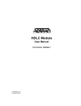
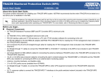
April 2000
61200307L1-19B
Installation Instructions
T1 Network Interface Module
P/N 1200307L1
Installing the T1 Network Interface Module
Figure 1 represents the actions required for proper placement of the T1 Network Interface Module. Perform
the following steps to install the network module:
1.
2.
Remove the cover plate from the appropriate Network slot.
Slide the T1 Network Interface Module into the ATLAS 550 chassis until the module is firmly seated
in the ATLAS 550 unit.
3.
Fasten the thumbscrews at both edges of the network module. Tighten with a screwdriver.
4.
Connect the cable to the associated device.
5.
Complete the installation of any remaining modules and the Base Unit as specified in the Installation
chapter of the ATLAS 550 User Manual.
Remove Cover Plate
O
O I
I
4
2
ALL EMPTY SLOTS MUST BE
COVERED WITH BLANK PANELS
NETWORK 2
NETWORK 1
FUSE RATING: 2A/250V SLO-BLO
ETHERNET
CONTROL
IN
NETWORK
T1 NETWORK MODULE
NETWORK
IN
OUT
RELAY
ALARM
MON
NC NO COM GND
MON
IN
TEST
OUT
CAUTION: FOR CONTINUED PROTECTION
AGAINST RISK OF FIRE, REPLACE ONLY
WITH SAME TYPE AND RATING OF FUSE.
90-240VAC, 2A, 50/60Hz
OUT
500 Series
Install Module
Figure 1. Installing the T1 Network Interface Module
See the ATLAS 550 User Manual for operation, configuration, and detailed specifications on the T1 Network
Interface Module (ADTRAN P/N 1200307L1).
WARNING:
61200307L1-19B
Option modules are intended to be serviced by qualified service personnel only.
T1 Network Interface Module Installation Instructions
1 of 1