1
C A U T I O N !
SUBJECT TO ELECTROSTATIC DAMAGE
OR DECREASE IN RELIABILITY.
HANDLING PRECAUTIONS REQUIRED.
Section 61245211L1-5
Issue 1, December 1998
CLEI Code # T1R6GMJDAA
PRACTICES
SINGLE-WIDE FT1 REPEATER
INSTALLATION/MAINTENANCE
1
2
3
4
5
6
7
8
9
10
11
12
GND
NC
T
CUSTOMER
LOOP 1
R
T
NETWORK
LOOP 1
R
NC
NC
NC
GND
NC
NC
FT1 REPEATER
1245211L1
Contents
1. General ................................................................................ 1
2. Installation ........................................................................... 3
3. Installation of FT1 Repeaters in ADTRAN
Apparatus Cases .................................................................. 3
4. Maintenance ........................................................................ 4
5. CSA Deployment Guidelines .............................................. 5
6. Specifications ...................................................................... 6
7. Warranty and Customer Service ......................................... 6
Appendix A. FT1 Loopbacks .............................................. A-1
Figure 1.
Figure 2.
Figure 3.
Figure 4.
Figure A-1.
Figure A-2.
Figure A-3.
Figure A-4.
Figure A-5.
Figure A-6.
Table A.
Table B.
Table C.
Table D.
Figures
ADTRAN Single-Wide FT1 Repeater ................. 1
ADTRAN Single-Wide FT1 Repeater
Connector Pinout .................................................. 3
FT1 Repeater Network Loopback ........................ 4
CSA Deployment Guidelines ............................... 5
FT1 Loopbacks ................................................ A-1
FT1 DP Network Loopback ............................ A-1
FT1 DP CPE Loopback ................................... A-1
FT1 Repeater Network Loopback .................. A-2
FNID Network Loopback ............................... A-2
FNID CPE Loopback ...................................... A-2
Tables
LED Indications ....................................................
FT1 Repeater Apparatus Cases .............................
Loop Insertion Loss Data .....................................
HDSL FT1 Repeater Unit Specifications .............
3
3
4
6
Table A-1. FT1 Loopback Select Codes ............................. A-3
1. GENERAL
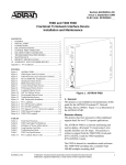
This practice provides installation and maintenance
procedures for the ADTRAN Single-Wide
Fractional T1 (FT1) Repeater, (ADTRAN P/N
1245211L1), illustrated in Figure 1.
The ADTRAN Single-Wide FT1 Repeater is a
device used to extend the effective range of an
ADTRAN FT1 circuit. It is capable of doubling the
deployment range of standard HDSL, providing a
carrier service area (CSA) compliant loop on both
sides of the Single-Wide FT1 Repeater.
61245211L1-5A
Figure 1. ADTRAN Single-Wide FT1 Repeater
Features of the Single-Wide FT1 Repeater include:
• 2B1Q line coding
• Range up to 12 kft of 24-gauge wire each direction
from FT1 Repeater
• Lightning protection
• Remote loopback control
• Coexists with DDS and ISDN repeaters in same
apparatus case
• Remote performance monitoring capability
This unit is used in conjunction with any span
powering FT1 DP for the central office and span
powered FNID remote end as follows:
Part Number
Unit Name
1245206L1 ........... Siemens FT1 DP
1245207L1 ........... Northern Telecom FT1 DP
1245208L1 ........... ALCATEL FT1 DP
1245205L1 ........... WECO D4 FT1 DP
1245201L1 ........... FNID (T400)
1242046L2 ........... Siemens FT1 DP
1242047L2 ........... Northern Telecom FT1 DP
1242048L2 ........... Alcatel FT1 DP
1242040L2 ........... AT&T FT1 DP
1242041L2 ........... FNID (T400)
1242042L2 ........... FNID (standalone)
The ADTRAN Single-Wide FT1 Repeater provides
a means of extending the digital subscriber loop
serving range using a centrally-located unit. There
are no manual option settings on the Single-Wide
FT1 Repeater.
Issue included
1
Trademarks: Any brandSection
names 61245211L1-5,
and product names
in this document are
trademarks, registered trademarks, or trade names of their respective holders.
1
The ADTRAN Single-Wide FT1 Repeater provides
three faceplate LEDs which indicate signal quality,
error conditions, and loopback status. See Table A
for a description of the LED indicators.
Operating power is derived from an ADTRAN FT1
DP, independent of line impedance or wire gauge.
The repeater uses some current, then passes the span
power on to the FNID.
The Single-Wide FT1 Repeater operates at line
losses up to 35.25 dB at 200␣ kHz, in both directions
from the repeater and regenerates the 2B1Q signals
to meet the transmitted power spectrum of Bellcore
TA-NWT-0001210. For deployment guidelines,
refer to subsection 5 of this practice.
The Single-Wide FT1 Repeater is housed in an
environmental apparatus case.
NOTE
Do not remove the metal shell enclosing the
circuit packs.
Table A. LED Indications
1245211L1
FT1 RPTR
LED
Description and Indications
NET
This LED indicates the FT1 signal quality and errors on the Network-side loop. The NET LED will
flash once when an errored second is detected on NET side loop. If the NET LED flashes yellow
rapidly (six times per second), sealing current is present and the FT1 Repeater is attempting to
synchronize with the other FT1 circuit elements.
Off ........ No synchronization with the FT1 DP.
Green .... Synchronized with good signal quality on NET loop (> 2dB margin above 10–7 BER)
Yellow .. Synchronized with marginal signal quality on NET loop (< 2 dB margin above 10–7 BER)
Red ........ Synchronized with poor signal quality on NET loop (>10–7 BER)
NET
CUST
LBK
CUST
This LED indicates the FT1 signal quality and errors on the Customer-side loop. The CUST LED
will flash once when an errored second is detected on CUST side loop.
Off ........ No synchronization with the FNID.
Green .... Synchronized with good signal quality on CUST loop (> 2dB margin above 10–7 BER)
Yellow .. Synchronized with marginal signal quality on CUST loop (< 2 dB margin above 10–7 BER)
Red ........ Synchronized with poor signal quality on CUST loop (>10–7 BER)
LBK
This LED indicates the status of a loopback detected at the FT1 Repeater.
Off ........ No loopback detected at the FT1 Repeater.
Yellow .. Loopback detected toward NET.
2
Section 61245211L1-5, Issue 1
61245211L1-5A
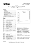
The connector pinout for the Single-Wide FT1
Repeater is shown in Figure 2.
2. INSTALLATION
CAUTION
This equipment contains static-sensitive
components. Be sure to follow proper
electrostatic discharge procedures before
handling or installing the equipment.
GND
NC
T
CUSTOMER
LOOP 1
R
T
NETWORK
LOOP 1
R
NC
NC
NC
GND
NC
NC
The Single-Wide FT1 Repeater circuit pack is
shipped in a separate carton and must be installed in
an environmental apparatus case.
Figure 2. ADTRAN Single-Wide FT1 Repeater
Connector Pinout
Table B. FT1 Repeater Apparatus Cases
1
2
3
4
5
6
7
8
9
10
11
12
Remove the Single-Wide FT1 Repeater circuit pack
from the carton and visually ensure that damage has
not occurred during shipping or handling. If
damage has occurred, file a claim immediately with
the carrier, then contact ADTRAN customer service.
The Single-Wide FT1 Repeater circuit pack is
designed for installation in a pre-wired apparatus
case. These are described in Table B.
Revision History
This is the first issue of this practice. In subsequent
issues, revisions will be summarized in this
paragraph.
ADTRAN
Part
Number
1150027L1
1150027L2
1152010L3
1152010L4
1150057L1
1150057L2
1150058L1
1150058L2
Description
FT1
Repeaters
... 4-Slot, Dual T1 form, air ........ 4
... 4-slot, Dual T1 form, gel ........ 4
... 2-slot, Dual T1 form, gel ........ 2
... 2-slot, Dual T1 form, air ......... 2
... 4-slot, Universal, air ............... 4
... 4-slot, Universal, gel ............... 4
... 8-slot, Universal, air ............... 6
... 8-slot, Universal, gel ............... 6
3. INSTALLATION OF SINGLE-WIDE FT1
REPEATERS IN ADTRAN APPARATUS
CASES
When installing the Single-Wide FT1 Repeater in an
ADTRAN apparatus case, refer to the ADTRAN
Installation/Maintenance practice for the apparatus
case being used.
CAUTION
The housing must be considered to be under
pressure and should be handled accordingly.
The Single-Wide FT1 Repeater dissipates a
maximum of 3 watts.
61245211L1-5A
Section 61245211L1-5, Issue 1
3
4. MAINTENANCE
The ADTRAN Single-Wide FT1 Repeater requires
no routine maintenance. In case of equipment
malfunction, perform an in-band loopback from the
central office (CO), as described in Appendix A of
this practice. If a malfunction is confirmed, replace
the Single-Wide FT1 Repeater.
FT1 Repeater Loopbacks
The Single-Wide FT1 Repeater has looping
capability through the channel which allows for
digital loopback to help isolate faults. The looping
is accomplished remotely from the CO switch as
described in Appendix A.
Replacement of Circuit Packs
When testing indicates a faulty circuit pack, refer to
the apparatus case installation/maintenance practice
for the entry and pressurization control. Replace the
faulty circuit pack. Request a loopback test from
the CO, per Appendix A.
ADTRAN does not recommend field repair of the
circuit pack. Repair services may be obtained by
returning the defective unit to the ADTRAN Repair
Department.
Testing the FT1 Repeater at the CO
The ADTRAN Single-Wide FT1 Repeater performs
the loopback described in Appendix A.
The FT1 Repeater network loopback is a digital
loopback toward the CO, as illustrated in Figure 3.
HDSL
DSX-1
Interface
Central
Office
FT1 DP
D4
Channel Bank
DS1
Interface
FT1
Repeater
FT1-NID
Customer
Premises
Local Loop
Figure 3. FT1 Repeater Network Loopback
This loopback is initiated by the DDS latching
loopback code for NEI Position 1 (N1000001). The
NEI Position 1 latching loopback is detected in the
primary DS0 of the FT1 circuit (the channel in
which the FT1-DP is physically installed) to control
the looping of the FT1 circuit. When the FT1
circuit is looped, all DS0s in use will be looped.
The DS0s in use will also be transmitted on to the
customer. This loopback is also initiated from the
craft interface or the LB push-button at the FT1-DP.
FT1 Self-Test
When a self-test is initiated at the FT1-DP, a
repeater failure will be indicated as an FNID failure
on the craft interface screens. Likewise, if a
self-test is initiated at the FNID, a repeater failure
will be indicated as an FT1-DP failure on the craft
interface screens.
4
Section 61245211L1-5, Issue 1
61245211L1-5A
5. CSA DEPLOYMENT GUIDELINES
The ADTRAN FT1 DSL system including the
ADTRAN Single-Wide FT1 Repeater is designed to
provide Fractional DS1 based services over loops
designed to comply with Carrier Service Area
(CSA) guidelines. CSA deployment guidelines are
given below.
1.
2.
3.
4.
5.
6.
Recommended maximum local loop loss
information for PIC cable at 70°F, 135Ω, resistive
termination is provided in Table C.
Table C. Loop Insertion Loss Data
Frequency
(Hz)
All loops are non-loaded only.
For loops with 26-AWG cable, the maximum loop
length including bridged tap lengths is 9 kft.
For loops with 24-AWG cable, the maximum loop
length including bridged tap lengths is 12 kft.
Any single bridged tap is limited to 2 kft.
Total bridged tap length is limited to 2.5 kft.
The total length of multi-gauge cable containing 26AWG cable must not exceed:
12 - {(3*L26)/9} - LBTAP (in kft)
L26 = Total length of 26-AWG cable excluding
bridged taps (in kft)
LBTAP = Total length of all bridged taps (in kft)
3000 ...................... 12.0
10,000 ...................... 15.0
50,000 ...................... 25.5
100,000 ...................... 30.0
150,000 ...................... 32.75
200,000 ...................... 35.25
An approximation for the maximum amount of
wideband noise on a DSL local loop as measured by
a 50 kbps filter is ≤ 31 dBrn.
An approximation for the maximum level of
impulse noise as measured using a 50 kbps filter on
an DSL loop is ≤ 50 dBrn.
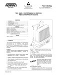
This deployment criteria is summarized in the chart
shown in Figure 4.
NOTE
These approximations are to be used
as guidelines only and may vary slightly
on different loops. Adhering to the
guidelines
should
produce
performance in excess of 10-7 BER.
WORKING LENGTH OF 24 GAUGE (OR COARSER) CABLE (KFT)
12
11
Maximum Loss
(dB)
INVALID CSA CABLE LENGTHS
10
TOTAL
BRIDGED
2.5
TAP
2.0
1.5
LENGTH
1.0
(KFT)
0.5
0.0
9
8
7
6
5
4
3
2
VALID CSA CABLE LENGTHS
1
0
0
1
2
3
4
5
6
7
8
9
WORKING LENGTH OF 26 GAUGE CABLE (KFT)
Figure 4. CSA Deployment Guidelines
61245211L1-5A
Section 61245211L1-5, Issue 1
5
6. SPECIFICATIONS
Specifications for the ADTRAN Single-Wide FT1
Repeater appear in Table D.
7. WARRANTY AND CUSTOMER SERVICE
ADTRAN will replace or repair this product within
ten years from the date of shipment if it does not
meet its published specifications or fails while in
service (see ADTRAN Equipment Warranty,
Repair, and Return Policy and Procedure).
Return Material Authorization (RMA) is required
prior to returning equipment to ADTRAN.
For service, RMA requests, or further information,
contact one of the following numbers.
ADTRAN Customer Service
ADTRAN Telco Technical Support . (800) 726-8663
Standard support hours ..................... Monday-Friday
7 a.m. - 7 p.m. CST
Emergency support ......... 7 days/week, 24 hours/day
Sales .................................................. (800) 827-0807
RMA (repair service) ....................... (256) 963-8722
Repair and Return Address
ADTRAN, Inc.
Customer and Product Support (CAPS) Department
901 Explorer Boulevard
Huntsville, Alabama 35806-2807
Table D. HDSL FT1 Repeater Unit Specifications
Loop Interface
Modulation Type .................................. 2B1Q
Mode ..................................................... Full Duplex, Echo Cancelling
Number of Pairs ................................... One
Bit Rate ................................................. 784 kbps per pair
Baud Rate ............................................. 392K baud per pair
Service Range ...................................... Defined by Carrier Service Area Guidelines
Loop Loss ............................................. 35.25 dB maximum @ 200 kHz
Bridged Taps ........................................ Single Taps < 2 kft, Total Taps < 2.5 kft
Performance ......................................... Compliant with Bellcore TA-NWT-001210
Return Loss .......................................... 20 dB (40 kHz to 200 kHz)
HDSL Tx Signal Level ........................ 13.5 dBm
Input Impedance ................................... 135 Ω
Power
Input Power .......................................... (span-powered by FT1 DP) 3 W maximum
Tests
Diagnostics ........................................... Loopback initiated with DDS latching loopback codes.
Self test initiated from FT1-DP or FNID.
Physical
Dimensions ........................................... 6.36" long, 2.60" high, 0.7" deep
Weight .................................................. 12 ounces
Environment
Temperature ......................................... Operating (Standard) ............ -40°C to +50°C
Storage .................................. -40°C to +85°C
Part Number
ADTRAN Single-Wide FT1 Repeater 1245211L1
6
Section 61245211L1-5, Issue 1
61245211L1-5A
APPENDIX A
FT1 LOOPBACKS
1. GENERAL
This Appendix is an overall reference to the
loopback capabilities of the ADTRAN Fractional T1
system. Included in the Appendix is a description of
the FT1 loopbacks and the methods for activating
the FT1 loopbacks.
The FT1 DP network loopback is a digital loopback
toward the CO (see Figure A-2). This loopback is
initiated by the OCU latching loopback command
(N1010101), by a push-button when available, or by
the craft interface. The OCU latching loopback
code is detected in the primary DS0 of the FT1
circuit -- the channel where the FT1 DP is
physically installed -- to control the FT1 circuit
looping. When the FT1 circuit is looped, all DS0s
in use will be looped back toward the network. The
DS0s will be transmitted on to the customer.
2. FT1 LOOPBACKS
Figure A-1 shows the application from the central
office (CO) to customer premises. The FT1
Repeater is shown for convenience and not as a
necessary part of the FT1 network. The loopbacks
shown are as follows:
A.
B.
C.
D.
E.
The FT1 DP CPE loopback is a digital loopback
toward customer premises as shown in Figure A-3.
This loopback is initiated by the RLB button on the
FNID, or by the craft interface. When the FT1
circuit is looped, all DS0s in use will be looped back
toward the customer. All DS0s sent toward the
network will be filled with all-1s.
FT1 DP network loopback
FT1 DP CPE loopback
FT1 Repeater network loopback
FNID network loopback
FNID CPE loopback
There are two loopbacks available to the FT1 DP.
The FT1 DP network loopback loops the FT1 signal
back to the network. The FT1 DP CPE loopback
loops the FT1 signal back to the customer.
DSX-1
Interface
Central
Office
FT1
Repeater
FT1 DP
A
B
C
T1 NIU
FNID
D
Customer
Premises
Equipment
E
D4
Channel Bank
Figure A-1. FT1 Loopbacks
DSX-1
Interface
FT1 DP
DS1
Interface
HDSL
FNID
Central
Office
Local Loop
Customer
Premises
D4
Channel Bank
Figure A-2. FT1 DP Network Loopback
DSX-1
Interface
Central
Office
FT1 DP
HDSL
DS1
Interface
FNID
Local Loop
D4
Channel Bank
Customer
Premises
Figure A-3. FT1 DP CPE Loopback
61245211L1-5A
Section 61245211L1-5, Issue 1
A-1
There is one loopback available to the FT1
Repeater. The FT1 Repeater Network loopback is a
digital loopback toward the CO as shown in Figure
A-4. The loopback is initiated by the DDS latching
loopback code for NEI Position 1 (N1000001). The
NEI Position 1 latching loopback is detected in the
primary DS0 of the FT1 circuit, the channel where
the FT1 DP is physically installed, to control the
looping of the FT1 circuit. When the FT1 circuit is
looped, all DS0s in use will be looped. The DS0s in
use will also be transmitted on to the customer.
This loopback is also initiated by the craft interface
or by the RLB push-button (when available) at the
FT1-DP.
There are two loopbacks available to the FNID. The
FNID network loopback loops the FT1 signal back
toward the network. The FNID CPE loopback loops
the FT1 signal back toward the customer.
The FNID network loopback is a digital loopback
toward the CO as illustrated in Figure A-5. This
loopback is initiated by the DDS latching loopback
code (NEI Position 1 - N1000001 for a nonrepeatered loop, or NEI Position 2 -N1000001 for a
repeatered loop), by the craft interface, or by the
RLB button at the FT1-DP. The NEI Position 1
latching loopback is detected in the primary DS0 of
the FT1 circuit -- the channel in which the FT1 DP
is physically installed -- to control the looping of the
FT1 circuit. When the FT1 circuit is looped, all
DS0s in use will be looped. The loopback keep
alive code will be transmitted to the customer.
The FNID CPE loopback is a digital loopback
toward customer premises as shown in Figure A-6.
This loopback is initiated by the craft interface.
When the FT1 circuit is looped, all DS0s in use will
be looped. The DS0s in use will be filled with all 1s
toward the network.
HDSL
DSX-1
Interface
Central
Office
FT1
Repeater
FT1 DP
FNID
DS1
Interface
Customer
Premises
D4
Channel Bank
Local Loop
Figure A-4. FT1 Repeater Network Loopback
DSX-1
Interface
Central
Office
FT1 DP
HDSL
DS1
Interface
FNID
Customer
Premises
Local Loop
D4
Channel Bank
Figure A-5. FNID Network Loopback
DSX-1
Interface
Central
Office
FT1 DP
HDSL
FNID
Local Loop
D4
Channel Bank
DS1
Interface
Customer
Premises
Figure A-6. FNID CPE Loopback
A-2
Section 61245211L1-5, Issue 1
61245211L1-5A
3. LOOPBACK ACTIVATION AND
DEACTIVATION
This section describes loopback activation and
deactivation methods for the ADTRAN Fractional
T1 system. Loopback activation and deactivation is
controlled with the push-button located on the front
panel, through craft interface, or latching loopback
codes.
Latching loopbacks for the FT1 system are activated
by transmitting the following latching loopback
sequence in the primary DS0 of the FT1 system:
A.Minimum of 35 transition in progress (TIP)
bytes (N0111010).
B.Minimum of 35 loopback select code (LSC)
bytes as defined in Table A-1.
C.Minimum of 100 loopback enable (LBE)
bytes (N1010110).
A push-button labeled “LBK,” located on the front
panel of the FNID, controls the activation of remote
loopback. Pressing this button activates the FT1 DP
CPE loopback. Two push-buttons, labeled “LCL”
and “REM,” respectively, are located on the front
panel of the FT1␣ DP. Press REM on the FT1 DP in
order to activate FT1 Repeater loopback (when
available) or FNID network loopback. To
deactivate Remote loopback, either press REM or
wait for the loopback timeout (if enabled).
D.Minimum of 35 all 1s bytes (S1111111),
plus a minimum of 100 LBE bytes. (N-1)
iterations, where N is the number of channel
units of the same type; i.e., same LSC; that
lie between the test center and the loopback
to be operated. This step is only used when
there are identical channel units in tandem.
E. Minimum of 32 far end voice (FEV) bytes
(N1011010).
Craft interfaces, located on the front panels of the
FNID and FT1␣ DP, allow access to the FT1 device
through an RS-232-type interface. All loopbacks
for the FNID, FT1 Repeater, and FT1 DP can be
controlled from the craft interface. The craft
interface located on the FNID faceplate can activate
and deactivate FNID network and FNID CPE
loopbacks; and remotely activate and deactivate FT1
Repeater network loopback, FT1 DP network
loopback, and FT1 DP CPE loopback. The craft
interface located on the FT1␣ DP faceplate can
activate and deactivate FT1 DP network loopback
and FT1 DP CPE loopbacks; and remotely activate
and deactivate the FT1 Repeater networkloopback,
FNID network loopback, and FNID CPE loopback.
FT1 DP, FT1 Repeater, and FNID network
loopbacks can be activated by the DDS
latching loopback sequence. The latching
loopback sequence is detected in the
primary DS0 of the FT1 system. When
the loopback is activated on the device,
the whole FT1 bandwidth is looped. The
FT1 DP, FT1 Repeater, and FNID each
respond to a different loopback select
code allowing for sectionalization of the
network during testing. Table A-1 is a list
of FT1 devices and their loopback select
code.
61245211L1-5A
A 25-second watchdog timer is activated between
the 35 TIP bytes and 35 LSC bytes, between the 35
LSC bytes and 100 LBE bytes, and between the 100
LBE bytes and 32 FEV bytes. The timer requires
the correct receipt of the latter sequences less than
25 seconds after receiving the prior sequence. This
prevents inadvertent setting of the latching
loopbacks.
Latching loopbacks for the FT1 system are
deactivated by transmitting the following latching
loopback sequence in the primary DS0 of the FT1
system:
Minimum of 25 TIP bytes (N0111010)
Table A-1. FT1 Loopback Select Codes
FT1 Device
Loopback Select
Code Name
Loopback Select
Code Byte
FT1 DP ..............................
FT1 Repeater .....................
FNID without repeater ......
FNID with repeater ...........
OCU loopback ......................
NEI Position 1 loopback ......
NEI Position 1 loopback ......
NEI Position 2 loopback ......
N1010101
N1000001
N1000001
N1000001
Section 61245211L1-5, Issue 1
A-3
4. LOOP-UP STATE
In the loop-up state, the active FT1 loopback will
provide a continuous loop for the FT1 bandwidth.
The data flow is continuously monitored for the
loop deactivation commands to deactivate the
loopbacks. Also, a loopback timeout is checked. If
the loopback timeout is enabled, any loopback that
is in the loop-up state in excess of the loopback
timeout will be deactivated.
A-4
Section 61245211L1-5, Issue 1
61245211L1-5A