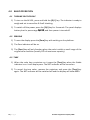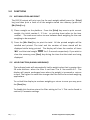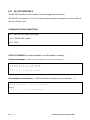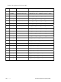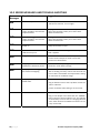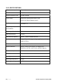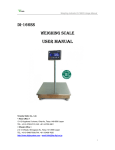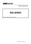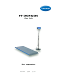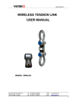
1
Adam Equipment AE‐401 INDICATORS (P.N. 9520, Revision B3, September 2008) 1 | P a g e © Adam Equipment Company 2008 Easy Reference: Model name of the scale: Serial number of the unit: Software revision number (Displayed when power is first turned on):
Date of Purchase: Name of the supplier and place: 2 | P a g e © Adam Equipment Company 2008 1.0 CONTENTS 1.0 CONTENTS ........................................................................................... 3
2.0 INTRODUCTION ................................................................................... 5
3.0 SET UP.................................................................................................. 6
3.1 FEATURES......................................................................................... 6
3.2 CONNECTIONS .................................................................................. 7
3.2.1 CONNECTION OF LOAD CELL ...................................................... 7
3.2.2 CONNECTION OF RS-232.............................................................. 7
3.3 DISPLAY / KEYBOARD FUNCTION .................................................. 8
3.4 LOCATING AND PROTECTING YOUR INDICATOR/SCALE ........... 9
3.4 LOCATING AND PROTECTING YOUR INDICATOR/SCALE ......... 10
3.5 PREPARING TO USE THE INDICATOR/SCALE ............................ 11
4.0 BASIC OPERATION............................................................................ 12
4.1 TURNING ON THE SCALE .............................................................. 12
4.2 ZEROING ......................................................................................... 12
4.3 TARE ................................................................................................. 12
5.0 FUNCTIONS........................................................................................ 13
5.1 ACCUMULATION AND PRINT......................................................... 13
5.2 HOLD FUNCTION (ANIMAL WEIGHING) ........................................ 13
6.0 RS-232 INTERFACE ........................................................................... 14
7.0 AUTOMATIC TURN OFF AND BUZZER............................................. 15
8.0 PARAMETERS .................................................................................... 16
8.1 SCALE DIVISION ................................................................................ 17
8.2 DISPLAY RESOLUTION .................................................................. 19
8.3 ZERO RANGE / ZERO TRACKING / WEIGHT UNIT SETUP ........... 20
8.4 BAUD RATE ..................................................................................... 21
8.5 SERIAL PRINTOUT PORT CONFIGURATION ............................... 21
8.6 AUTOMATIC BACKLIGHT ............................................................... 21
8.7 FILTER ............................................................................................. 22
8.8 VIEW ADC VALUES......................................................................... 22
9.0 CALIBRATION..................................................................................... 23
10.0 ERROR MESSAGES AND TROUBLE-SHOOTING......................... 24
11.0 SPECIFICATIONS............................................................................ 25
12.0 WARRANTY STATEMENT .............................................................. 26
3 | P a g e © Adam Equipment Company 2008 4 | P a g e © Adam Equipment Company 2008 2.0 INTRODUCTION The AE 401 weighing indicator is a precision instrument that includes a precision analog to digital converter and microprocessor, for stable and accurate weighing using load cell platforms or weighing assemblies. The case is stainless steel to provide better protection. It includes AC power supply, LCD display, low power consumption, compact structure, light weight and easy operation. Thus it is ideal for all weighing applications, including table scale, floor platforms and other weight measuring devices. The set‐up and configuration assumes a working knowledge of load cells and weighing applications and that the user has the necessary masses for calibration of the system. 5 | P a g e © Adam Equipment Company 2008 3.0 SET UP 3.1 FEATURES The Stainless Steel AE 401 Indicator is a general purpose weighing indicator for use with strain gauge load cells.
The indicator offers: • Large clear LCD display • Simple user‐friendly operations • Full range tare • RS‐232 Interface • Operation from internal rechargeable battery or mains power source • Lockable keyboard calibration and configuration for security • Selectable digital filtering for stability • Weighing up to 1:15,000 divisions • Supports up to four 350 ohm load cells • Unit of weight can be switched between kg and lb when enabled If the AE 401 has already been configured for use with a platform then proceed to section 3.3. However if the indicator has not been connected to a platform or configured then it is necessary to first connect the load cells to the indicator as shown in section 3.2.1 then configure and calibrate the scales as described in sections 6 and 7. 6 | P a g e © Adam Equipment Company 2008 3.2 CONNECTIONS 3.2.1 CONNECTION OF LOAD CELL For better performance of the electronic scale, make sure to connect the 5 pin round plug to the 5 pin socket firmly and tighten the screw. Please see figure 1: 1: Pin +IN +Signal 2: Pin ‐IN ‐Signal Figure 1 3: Pin AGND Shield 4: Pin +E, +S +Excitation, +Sense 5: Pin ‐E, ‐S ‐Excitation, ‐Sense Note: For 6 wire load cell, connect the load cell +Excitation and +Sense to pin 4 and –
Excitation and ‐Sense to pin 5. 3.2.2 CONNECTION OF RS‐232 RS‐232 serial interface is a D‐SUB‐9 plug as figure 2 shows: 2: Pin RXD 3: Pin TXD Figure 2 5: Pin GND 7 | P a g e © Adam Equipment Company 2008 3.3 DISPLAY / KEYBOARD FUNCTION The keys perform the following functions: KEYS FUNCTION
[O/I] On/Off function Tare the scale Zero setting of the scale; range of zero set is ±2% of total [Mode] Change weighing functions and weight display; On/off of background lighting [M+ Print] Accumulative printing of current weight [Print] Printing of current weight 8 | P a g e © Adam Equipment Company 2008 The AE‐401 indicator has the following LCD symbols: Bat Battery needs charging Stable The weight is stable Gross Gross weight is displayed NET A weight has been tared, the display is showing the net weight. Tare The scale has been tared. Zero The scale is at zero LCD display symbols: ‘Zero’ indication
9 | P a g e ‘Battery’
‘Tare Weight’
HL
Hold Function is active
‘Net weight’
oz ‘oz’ unit
‘Gross Weight’ lb ‘Lb’ unit © Adam Equipment Company 2008 3.4 LOCATING AND PROTECTING YOUR INDICATOR/SCALE In order to keeps your indicator functioning at its best we suggest that you do the following: Avoid extremes of temperature. Do not place in direct sunlight or near air conditioning vents. Make sure the unit is located on a strong table and free from vibration. Avoid unstable power sources. Do not use near large users of electricity such as welding equipment or large motors. Do not let the balance battery go flat – if you are not using it for a long time you should charge the battery up periodically to make sure the battery does not lose its charge. Keep free from vibration. Do not place near heavy or vibrating machinery. Do not use the indicator in areas with excessive water and don’t spray the scale or indicator with water when cleaning. Remove all water from the scale and indicator with a clean dry duster cloth. Do not place near open windows, air‐conditioning vents or fans that may cause a draft and unstable readings. 10 | P a g e © Adam Equipment Company 2008 3.5 PREPARING TO USE THE INDICATOR/SCALE 1) Put the indicator/scale on a firm level surface free from vibrations for accurate weight readings. 2) Adjust the four levelling feet (if installed) to set the level of scale platform. 3) Avoid operating the indicator in direct sunlight or drafts of any kind. 4) Take away any weight that might be on the platform before the indicator is switched on. 5) Once the indicator has been switched on, it will go through an LCD display test and then re‐zero to be ready for use. 6) Please note when [Batt] indicator on the display is shown, the internal battery needs to be charged. 7) All goods weighed should be placed in the centre of the platform for accurate weighing. The footprint of the goods being weighed should not extend over the edges of the platform. 11 | P a g e © Adam Equipment Company 2008 4.0 BASIC OPERATION 4.1 TURNING ON THE SCALE 1) To turn on the AE‐401, press and hold the [O/I ] key. The indicator is ready to weigh and set to zero after 0‐9 self‐checking. 2) To switch off the power press the [O/I] key for 3 seconds. The panel displays battery level in percentage ‘bpt 99’, and then power is turned off. 4.2 ZEROING 1) To zero the display press the [Zero] key with nothing on the platform. 2) The Zero indicator will be on. 3) The [Zero] key will only function when the scale is within a small range of the original zero condition (usually 10% of maximum capacity). 4.3 TARE 1) When the scale has a container on it press the [Tare] key when the Stable indicator is on. It will display zero. The NET indicator will be turned on. 2) To cancel the tare value, remove the container and press the [Tare] key again. The NET indicator will be switched off and the display will show 0000. 12 | P a g e © Adam Equipment Company 2008 5.0 FUNCTIONS 5.1 ACCUMULATION AND PRINT The RS‐232 output will print one line for each weight added (press the [Print] key) and then print a total of all the weights stored into memory (press the [M+/Print] key). 1) Place a weight on the platform. Press the [Print] key once to print current weight; the initial number 1, 2 3 etc. on printing sheet refers to the item number . The scale must return to zero between each weighing for the next weighing to be accepted. 2) Press the [M+ Print] key to print the total. All the printed weights will be totalled and printed. The total and the number of items stored will be displayed while being printed. The display will show the number of items ‘n××’ and the total weight ‘YYYYY’ for 1.5 seconds respectively. If you wish to clear the memory press [Zero] key during the time that the totals are being displayed. 5.2 HOLD FUNCTION (ANIMAL WEIGHING) The indicator/scale will automatically hold a weight value that is greater than 20 scale divisions when the filter is set from 2 to 9. See section 8.7. The display will remain unchanged even when the weight is increased or returns to zero. The higher the value the stronger the filter will be for animal weighing applications. To un‐Hold the display to continue weighing or return to zero you may press the [Zero] key. To disable this function return the filter setting to 0 or 1. This can be found in section 8, Parameter settings. 13 | P a g e © Adam Equipment Company 2008 6.0 RS‐232 INTERFACE The RS‐232 interface can be used to record weighing information. The RS‐232 connector is a 9 pin d‐subminiature socket mounted on a short cable at the rear of the scale. COMMUNICATION CONNECTION: Pin 2: RXD RS‐232 input (not used) Pin 3: TXD RS‐232 output Pin 5: GND OUTPUT FORMATS: (n=item number, w= the weight, u=units)
Continuous output: 14 ASCII Characters, leading zeros are spaces denoted by “_” + w w w w . w w w u u <cr><lf><lf>
1 2 3 4 5 6 7 8 9 10 11 12 13 l4
i.e. + _ 1 2 4 . 6 9 1 k g <cr> <lf><lf>
Accumulation into memory: 17 ASCII characters, leading zeros are spaces ( “_”)
1 2 3 4 5 6 7 8 9 10 11 12 13 14 15 16 17
n n n w w w w w w w . w sp u u <cr> <lf>
Example _ 1 2 _ _ _ _ _ 5 4 . 5 _ K G <cr><lf>
14 | P a g e © Adam Equipment Company 2008 Total from Accumulation memory: 1 2 3 4 5 6 7 8 9 10 11 12 13 14 15 16 17 18 19 20 21
T O T A L n n n w w w w w . w w sp u u <cr> <lf>
<lf>
<lf>
<lf>
<lf>
<lf>
Example TOTAL_12_ _ _ 9 6 2 , 5 _ k g <cr><lf>
<lf>
<lf>
<lf>
<lf>
<lf>
7.0 AUTOMATIC TURN OFF AND BUZZER To enable these parameters, it is necessary that the jumper on the circuit board within the indicator is set to the OFF position. Place the jumper on the pins marked OFF. To enable the calibration function and parameters (section 8) move the jumper to the pins marked ON. Depress [Tare] key until the display shows ‘OFF XX’, where XX denotes the time of shut‐down, 3, 10, 15 or 30 minutes, with 0 to disable the function. Press the [Print] key to increment the value and [Mode] to store it. Then the message ‘bp on’ or ‘bp off’ is displayed. To choose ‘On’ or ‘Off’ for indication of buzzing or non‐buzzing, press the [Print] key. After the choice, press the [Mode] key to resume weighing. 15 | P a g e © Adam Equipment Company 2008 8.0 PARAMETERS To enable the parameters and calibration, it is necessary that the jumper on the circuit board within the indicator is set to the ON position. Place the jumper on the pins marked ON, at JP1. To disable the calibration function and parameters move the jumper to the pins marked OFF. 1) Press and hold [Tare] until ‘CAL SP’ display on the screen. 2) And then Press [Mode] to enter into setup mode, 3) The display will show ‘SET’ or press [Mode] again to enter A‐D display counts, see Section 8.8. 4) Press [M+ Print] to enter the menu. The display will show the first parameter ‘d1’ for setting the scale division. 16 | P a g e © Adam Equipment Company 2008 8.1 SCALE DIVISION Either ‘d1 X.XXX’ or ‘d2 X.XXX’ will display.’d1’ is the division for single range display. (From 0.0001~50),‘d2’ is the smaller division for the dual range display. (From 0.0001~50). Example: For a 60kg scale, if ‘d1’ is set to 0.02kg, the scale will show a division of 0.02kg from 0kg to 60kg. If ‘d2’ is set to 0.005kg, the scale will show a division of 0.005kg from 0kg to 30kg and show a division of 0.01kg from 30kg to 60kg. See table 1. 1. Press [M+ Print] to switch between ‘d1’ and ‘d2’. 2. Press [Print] to change division. The display will cycle through all the division options; press [Mode] to confirm your choice. 3. Press [Mode] to confirm and continue to the next step. Note: If ‘d1’ is set, the scale will only be in single range display mode and ‘d2’ will be ignored. If ‘d2’ is set, the scale will only be in dual range display mode and ‘d1’ will be ignored. 17 | P a g e © Adam Equipment Company 2008 Table 1 for values of ‘d1’ and ‘d2’. No. Capacity Division d1 Division d2 1 1.5000kg 0.0001, 0.0002, 0.0005 0.0001kg( (0~0.6kg), 0.0002kg (0.6~1.5kg), n=15000 2 3.0000kg 0.0002, 0.0005, 0.001 0.0002kg( (0~1.5kg), 0.0005kg (1.5~3kg), n=15000 3 6.0000kg 0.0005,0.001, 0.002 0.0005kg( (0~3kg), 0.0001kg (3~6kg), n=12000 4 15.000kg 0.001, 0.002, 0.005 0.001kg( (0~6kg), 0.002kg (6~15kg), n=15000 5 30.000kg 0.002, 0.005, 0.01 0.002kg( (0~15kg), 0.005kg (15~30kg), n=15000 6 60.000kg 0.005, 0.01, 0.02 0.005kg( (0~30kg), 0.01kg (30~60kg), n=12000 7 150.00kg 0.01, 0.02, 0.05 0.01kg( (0~60kg), 0.02kg (60~150kg), n=15000 8 300.00kg 0.02, 0.05, 0.1 0.02kg( (0~150kg), 0.05kg (150~300kg), n=15000 9 600.00kg 0.05, 0.1, 0.2 0.05kg( (0~300kg), 0.1kg (300~600kg), n=12000 10 1000.0kg 0.1, 0.2, 0.5 0.1kg( (0~600kg), 0.2kg (600~1000kg), n=10000 11 1500.0kg 0.1, 0.2, 0.5 0. 1kg( (0~600kg), 0.2kg (600~1000kg), n=15000 12 2000.0kg 0.2, 0.5, 1 0.2kg( (0~1t), 0.5kg (1t~2t), n=10000 13 3000.0kg 0.2, 0.5, 1 0.2kg( (0~1.5t), 0.5kg (1.5t~3t, n=15000 14 5000.0kg 0.5, 1, 2 0.5kg( (0~3t), 1kg (3t~5t), n=10000 15 8000.0kg 1, 2, 5 1kg( (0~4t), 2kg (4t~8t), n=8000 16 10000kg 1, 2, 5 1kg( (0~5t, 2kg (5t~10t), n=10000 17 15000kg 1, 2, 5 1kg( (0~6t), 2kg (6t~15t), n=15000 18 20000kg 2, 5, 10 2kg( (0~10t), 5kg (10t~20t), n=10000 19 30000kg 2, 5, 10 2kg( (0~15t), 5kg (15t~30t), n=15000 20 40000kg 5, 10, 20 5kg( (0~30t), 10kg (30t~40t), n=8000 18 | P a g e © Adam Equipment Company 2008 8.2 DISPLAY RESOLUTION ‘n XXX.XX’ will display on screen. The value shown is the display resolution. Display resolution = (full capacity) kg / (division) kg For dual range display, please refer to Table 1 for value of ‘n’. Ignore the decimal point shown and take the value as a whole number. Example: take ‘n 060.00’ as 6000, take ‘n 120.00’ as 12000. 1) Press [M+ Print] to select the digit to be changed (flashing digit) and print to increase (cycles through 0‐9 and back). 2) Press [Mode] to confirm value and enter in to the next step. Note: Calibrate the scale again after changing ‘Division’ and ‘Display Resolution’ settings. 19 | P a g e © Adam Equipment Company 2008 8.3 ZERO RANGE / ZERO TRACKING / WEIGHT UNIT SETUP The parameter ‘Ut ABCD’ will allow settings for initial zero range, auto zero range, the secondary weighing unit and the primary weighing unit. The ‘ ABCD’ are 4
numbers that describe the operation when they are set as shown below.
Initial Zero range = A 1) ‘Ut ABCD’ will be displayed. 2) The initial zero range (A value) allowed when power is first turned on, 1 to 9 mean 10% to 90% of maximum. 0 means do not set the initial zero. 3) Press the [M+ Print] key to change the flashing digit and the [Print] key to increment the digit. Auto Zero range = B 4) The range the auto zero will be active within (B value) is set by the next digit. 1 to 9 means 0.3 divisions to 2.7 divisions. (B x 0.3d). 0 means auto zero is disabled. Secondary Weight unit = C and Primary Weighing unit =D The values of C and D can be set to a range of 0‐9, however the following are the only active settings: ‘Ut XX10’ allows the [Mode] key to select either kilograms or pounds. The scale is calibrated in kilograms.
‘Ut XX00’ allows only the kilogram mode.
‘Ut XX01’ allows only the pounds mode
After setting the 4 values press the [Mode] key to confirm and advance to the next parameter. 20 | P a g e © Adam Equipment Company 2008 8.4 BAUD RATE 1) ‘b XXXX’ will display on the screen. The value shown is the baud rate. 2) Press [Print] to switch between baud rate of 1200, 2400, 4800 and 9600. 3) Press [Mode] to confirm. 8.5 SERIAL PRINTOUT PORT CONFIGURATION 1) ‘Ads XX’ will display on screen. The XX values decide the print mode. 2) Press [M+ Print] to select the active digit position of X. 3) Press [Print] to change the value of the selected digit. 4) Press [Mode] to confirm and return to normal weighing mode. Note: AdS 00 = Continuous output mode. 99 = Manual print mode with [Mode] or [M+ Print], see section 5.1 Any other number will be ignored and the RS‐232 will be off. 8.6 AUTOMATIC BACKLIGHT ‘bAn X’ will display. Press [Print] to change the value of ‘X’. 1) X=1: Automatic backlight. The backlight will turn on automatically when weight is on the scale, and will off after the weight is removed. 2) X=0: manual backlight. Press [Mode] and hold for 3 seconds to turn on/off the backlight. 21 | P a g e © Adam Equipment Company 2008 8.7 FILTER • The value as set previously will be displayed (for ex. ‘F L t 0’). • Press the [Print] key to scroll through the other options (0 to 9 see Note as given below). • Select the desired setting by pressing [Mode] and return to weighing. Note: FLt 0 = standard filter. 1 = Increased filter. 2 to 9 = progressively greater filter with hold for animal weighing. 8.8 VIEW ADC VALUES Pressing the [Mode] key twice after the display shows ‘CAL SP’ will access the ADC (analog to digital converter) values from the load cell. Press the [M+ Print] to see the values. Press the [Mode] key to return to normal weighing. 22 | P a g e © Adam Equipment Company 2008 9.0 CALIBRATION Before calibration, remove outer case of the indicator and set circuit breaker at ‘On’ position on the circuit board 1) Press [Tare] key until ‘CALSP’ is shown. 2) The indicator will display ‘CALSP’ 3) Press [M+ Print] key to enter calibration mode. The display will show ‘CAL 00’ 4) With no load on the scale and the display stable, press the [Mode] key to enter the mode of automatic zero check and ‘----‘ will be displayed. 5) Several seconds later, the weight of the previous calibration will be displayed, such as 150.00kg or if previously aborted 0000. 6) Place the calibration mass to be used on the scale. Allow time for the weight to become stable. If this mass is the value displayed press [Mode] key then go to step 9. 7) If the displayed value must be changed, press the [M+ Print] key, and the digit position flashing will move from one digit to the next adjacent. 8) Then press [Print] key to increment the flashing digit increasing from 0 to 9 in a cycle. Repeat above operation till a value representing the calibration mass is displayed, for example 20.00, then press the [Mode] key. 9) The equipment displays ‘- - - -‘, indicating entry into calibration and then reverts to normal weighing. 10) Remove the calibration weight and ‘0.00kg’ will be displayed on the equipment. At this time, zero indicator lights, denoting there is nothing being weighed on the measuring station. 11) To prevent unauthorised calibration set the jumper on the circuit board at ‘Off’ position). 23 | P a g e © Adam Equipment Company 2008 10.0 ERROR MESSAGES AND TROUBLE‐SHOOTING Error
Messages
Possible Causes
Err E
The memory has failed. Suggestions
Turn off power switch at the rear of the scale and wait for ten seconds. Turn on again. Err 1
A/D value is less than normal range, the ADC or the load cell may have failed. Unplug the load cell connection. If the problem still exists then the ADC is faulty. If not then check cables and load cells. Err 2
A/D value is bigger than normal range, the ADC or the load cell may have failed. Unplug the load cell connection. If the problem still exists then the ADC is faulty. If not then check cables and load cells. Err 3
Zero point is abnormal when power on. Check ADC counts in parameters for stability or verify connections to scale. Err 4
A/D value is too small when calibrate zero point. Ensure load cell is not damaged and that any dead load is applied. Err 5
Range calibration has failed. Check that load cell is wired correctly and is the correct size and output for scale. Ensure that correct mass was loaded. Err 6
Weighing value can not be stabilized in calibration period. Check load cell for liquid ingress, or environmental influences. Check battery charge. OUEr
Weighing value is bigger then the maximum weighing. Enter A/D value display, then check whether the ADC is working correctly. Ensure that the load cell has not been overloaded. Check parameter setting for max value or recalibrate range. Weighing display will not show stable value. Check the battery for correct charge. Plug in different scale to test if problem is with the scale or indicator. Ensure increment value setting is not too small. Can not turn on the power Ensure that power switch at the rear is turned on. Plug in the adapter and check that the “POWER” LED on the front of the indicator is lit. Test voltage on the battery to ensure that it is charging above 6 volts. Check load cell and RS232 connection to see if any are shorted. 24 | P a g e © Adam Equipment Company 2008 11.0 SPECIFICATIONS A/D conversion speed 40 times/ sec. Internal resolution ratio 400,000 External resolution ratio 1/1000‐1/15000 Power supply DC6V1.2Ah Rechargeable battery And AC/DC 12V 500mA adapter power; Non‐linear error <0.016% F.S Range of signal input of the transducer 0‐20mV Input range of load cell 0 ~ 20 mv Load cell excitation + 5V DC Load cell drive capacity up to 4, 350Ω or 1000Ω load cells Display 7‐digit LCD (with background lighting) display with digit height of 22mm Calibration Lockable keyboard calibration Symbol indication battery; stable; gross weight; net weight; tare deduction; zero set; carat; ounce; pound; kilogram; Power consumption 0.1VA Overall dimension 210 x 140 x 88 mm Net weight 0.8 kg Operating temperature 0C‐40C Operating humidity ≤85% RH 25 | P a g e © Adam Equipment Company 2008 12.0 WARRANTY STATEMENT Adam Equipment offers Limited Warranty (Parts and Labor) for the components failed due to defects in materials or workmanship. Warranty starts from the date of delivery. During the warranty period, should any repairs be necessary, the customer must inform the supplier or Adam Equipment. The company or its authorised Technician reserves the right to repair or replace any components at its own discretion. Any shipping cost involved in sending the faulty units to a service centre is the customers’ responsibility. The warranty will cease to operate if the equipment is not returned in the original packaging and with correct documentation for a claim to be processed. All claims are at the sole discretion of Adam Equipment. This warranty does not cover equipment where defects or poor performance is due to misuse, accidental damage, exposure to radioactive or corrosive materials, negligence, faulty installation, unauthorised modifications or attempted repair or failure to observe the requirements and recommendations as given in this User Manual. Repairs carried out under the warranty does not extend the warranty period. Components removed during the warranty repairs become the company property of Adam Equipment. The statutory right of the purchaser is not affected by this warranty. The terms of this warranty is governed by the Laws of England and Wales. For complete details on Warranty Information, see the terms and conditions of sale available on our web‐site. 26 | P a g e © Adam Equipment Company 2008 Manufacturer’s Declaration of Conformity This product has been manufactured in accordance with the harmonised European standards, following the provisions of the below stated directives: Electro Magnetic Compatibility Directive 2004/108/EC Low Voltage Directive 2006/95/EC Adam Equipment Co. Ltd. Bond Avenue, Denbigh East Milton Keynes, MK1 1SW United Kingdom FCC COMPLIANCE This equipment has been tested and found to comply with the limits for a Class A digital device, pursuant to Part 15 of the FCC Rules. These limits are designed to provide reasonable protection against harmful interference when the equipment is operated in a commercial environment. The equipment generates, uses, and can radiate radio frequency energy and, if not installed and used in accordance with the instruction manual, may cause harmful interference to radio communications. Operation of this equipment in a residential area is likely to cause harmful interference in which case the user will be required to correct the interference at his own expense. Shielded interconnect cables must be employed with this equipment to insure compliance with the pertinent RF emission limits governing this device. Changes or modifications not expressly approved by Adam Equipment could void the user's authority to operate the equipment. WEEE COMPLIANCE Any Electrical or Electronic Equipment (EEE) component or assembly of parts intended to be incorporated into EEE devices as defined by European Directive 2002/95/EEC must be recycled or disposed using techniques that do not introduce hazardous substances harmful to our health or the environment as listed in Directive 2002/95/EC or amending legislation. Battery disposal in Landfill Sites is more regulated since July 2002 by regulation 9 of the Landfill (England and Wales) Regulations 2002 and Hazardous Waste Regulations 2005. 27 | P a g e
© Adam Equipment Company 2008
© Copyright by Adam Equipment Co. Ltd. All rights reserved. No part of this publication may be reprinted or translated in any form or by any means without the prior permission of Adam Equipment. Adam Equipment reserves the right to make changes to the technology, features, specifications and design of the equipment without notice. All information contained within this publication is to the best of our knowledge timely, complete and accurate when issued. However, we are not responsible for misinterpretations which may result from the reading of this material. The latest version of this publication can be found on our Website. Many aspects of design and internal operation of these scales are protected by Trade Mark and Patent Protection. Head Office: Adam Equipment Co. Ltd. Bond Avenue, Milton Keynes, MK1 1 SW United Kingdom Tel: +44 (0)1908 274545 Fax: +44 (0)1908 641339 [email protected] For regional office worldwide visit www.adamequipment.com ADAM EQUIPMENT is an ISO 9001:2000 certified global company with more than 35 years experience in the production and sale of electronic weighing equipment. For a complete listing of all Adam scales and balances visit our website at: www.adamequipment.com
28 | P a g e
© Adam Equipment Company 2008