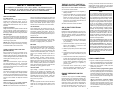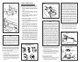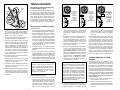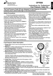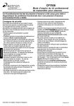
1
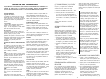
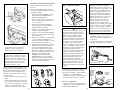
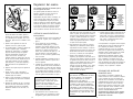
9. Llevar a cabo los pasos 1 a 8 para el sistema de
avance centrífugo si es que todavía no se ha
hecho.
Inductive Timing Light
Inductive Advance
Timing Light
D. C. Powered Timing
Light
GARANTIA COMPLETA DE UN (1) AÑO
Actron Manufacturing Company, 15825
Industrial Parkway, Cleveland, Ohio 44135,
garantiza al usuario que este equipo estará
libre de defectos en los materiales y
fabricación por un período de un (1) año a
partir de la fecha de compra original.
10.Apagar el motor y conectar la bomba de vacío
externa al diafragma de vacío en el distribuidor o a
la computadora a bordo del vehículo.
11.Poner el control de avance de la luz de regulación
en “0”. Volver a arrancar el motor.
Cualquier equipo que llegue a fallar dentro
de este período será reparado o reemplazado
a entera discreción de ACTRON y sin cargo
cuando sea devuelto a la fábrica. ACTRON
solicita que junto con el equipo se envíe una
copia de la boleta de venta original fechada,
si el período de garantía todavía está en
efecto.
12. Apuntar la luz de regulación a las marcas de
regulación, pulsar el gatillo y observar la
regulación del motor.
13.Ajustar la velocidad (rpm) del motor si es
necesario, y aplicar los niveles de vacío al
diafragma de vacío del avance, como se indica en
el manual de servicio del vehículo. (Si es
necesario reajustar las rpm del motor según las
instrucciones del manual de servicio del motor,
observar nuevamente la regulación del motor
como se indica en el paso 12).
Esta garantía no cubre los daños causados
por accidente, modificaciones o el uso
inapropiado o irrazonable. Los componentes
de duración limitada, por ej., baterías,
fusibles, bombillas de luces, tubos
destellantes, quedan excluidos del amparo
de esta garantía.
ACTRONS
PRODUCTS
NO
SE
RESPONSABILIZA
POR
DAÑOS
FORTUITOS O EMERGENTES DEBIDO AL
INCUMPLIMIENTO DE CUALQUIER
GARANTIA ESCRITA SOBRE ESTE
EQUIPO. Algunos estados no aceptan el
rechazo de responsabilidad por daños
fortuitos o emergentes, por lo tanto esta
negación de responsabilidad puede no servir
en el caso suyo. Esta garantía otorga
derechos legales específicos, y también
pueden existir derechos que varía de un
estado a otro.
14.Girar el control de avance de la luz de regulación
hacia arriba hasta que la marca de regulación en el
motor regrese a su punto de partida, como se
observó en el paso 12.
15.Observar el avance de regulación (en grados) con
cada aplicación de vacío y comparar el resultado
con los valores dados en el manual de servicio. Si
no se logra obtener las lecturas del avance de
vacío podría significar fugas en el diafragma,
mecanismo de avance pegajoso, o ausencia de
vacío para accionar el diafragma del motor de
vacío.
INSTRUCTIONS
INSTRUCCIONES EN ESPAÑOL
Vea la pagína 9
INTRODUCTION
Precise ignition timing is essential to achieve
maximum fuel economy and performance out
of any spark ignited engine. Your timing light
provides a simple method for timing the engines used in today’s vehicles. The advance
timing light provides the additional capability
of allowing the user to check timing advance
curves of the vacuum, mechanical or computer controlled types.
lyzers which are capable of measuring engine
RPM, and vacuum pumps for application of
vacuum when required. Contact him for further
information on these instruments. In the case
of engines which are equipped with breaker
point ignition systems, it will be necessary to
check and, if necessary, adjust point dwell
before adjusting timing. Make certain that the
instrument that you have or intend to purchase
has dwell measurement capability.
Virtually all engines require that timing, both
initial and advance calibrations be set, or
checked at specific engine speeds, or in some
cases with a specific vacuum applied to the
vacuum advance diaphragm on the distributor, or on the vehicle’s on-board computer.
Your supplier offers a number of engine ana-
Metal cased timing lights are for use on twelve
(12) volt negative (-) ground systems only.
Plastic cased timing lights may be used on six
(6) or twelve (12) volt, positive (+) or negative
(-) ground systems by following the simple
instructions in this manual.
IMPORTANT
CONSULT THE VEHICLE SERVICE MANUAL FOR SPECIFIC TUNE-UP INFORMATION
AND TEST PROCEDURES. ALWAYS FOLLOW THE MANUFACTURER’S
SPECIFICATIONS AND TEST PROCEDURES FOR ADJUSTING DWELL ANGLE AND
IDLE SPEED, ESPECIALLY ON VEHICLES WITH MODERN ELECTRONIC IGNITION AND
EMISSION CONTROLS. DO NOT ATTEMPT TO SERVICE A VEHICLE WITHOUT THE
MANUFACTURER’S INSTRUCTIONS AND SPECIFICATIONS.
16.Después de completar todas las pruebas, asegurar
de reajustar las velocidades en vacío y reconectar
las mangueras o conectores eléctricos que fueron
desconectados durante el procedimiento de
prueba.
VEHICLE MANUAL, SOURCES FOR SERVICE INFORMATION
The following is a list of publishers who have service manuals for your specific vehicle at nominal cost.
Write to them for availability and prices, specifying the make, style, and model year of your vehicle.
©1996 ACTRON MANUFACTURING CO.
15825 Industrial Parkway
Cleveland, Ohio 44135
0002-000-219201
PRINTED IN U.S.A.
16
American Motors Corporation
Myriad
8835 General Drive
Plymouth Township, MI 48170
Buick
Tuar Company
Post Office Box 354
Flint, MI 48501
Chrysler Corporation
Dyment Distribution Service
Service Publication
20770 Westwood Drive
Strongsville, OH 44136
Oldsmobile
Lansing Lithographers
Post Office Box 23188
Lansing, MI 48909
Ford Publications Department
Helm Incorporated
Post Office Box 07150
Detroit, MI 48207
Cadillac, Chevrolet, Pontiac
Helm Incorporated
Post Office Box 07130
Detroit, MI 48207
1
OTHER SOURCES- Nonfactory
Domestic and Import Cars
Chilton Book Company
Chilton Way
Radnor, PA 19089
Cordura Publications
Mitchell Manuals, Inc.
Post Office Box 26260
San Diego, CA. 92126
Motor’s Auto Repair Manual
Hearst Company
250 W. 55th Street
New York, NY 10019
SAFETY GUIDELINES
TO PREVENT ACCIDENTS THAT COULD RESULT IN SERIOUS INJURY
AND/OR DAMAGE TO YOUR VEHICLE OR TEST EQUIPMENT, CAREFULLY
FOLLOW THESE SAFETY RULES AND TEST PROCEDURES
SAFETY EQUIPMENT
lease on the parking brake when the gear shift
lever is removed from the PARK position. This
feature must be disabled when it is necessary
(for testing) to have the parking brake engaged
when in the DRIVE position. Refer to your
vehicle service manual for more information.
Fire Extinguisher
Never work on your car without having a
suitable fire extinguisher handy. A 5-lb or
larger CO 2 or dry chemical unit specified for
gasoline/chemical/electrical fires is recommended.
Fireproof Container
Rags and flammable liquids should be stored
only in fireproof, closed metal containers. A
gasoline-soaked rag should be allowed to dry
thoroughly outdoors before being discarded.
Safety Goggles
We recommend wearing safety goggles when
working on your car, to protect your eyes from
battery acid, gasoline, and dust and dirt flying
off moving engine parts.
HOT SURFACES
Avoid contact with hot surfaces such as exhaust manifolds and pipes, mufflers (catalytic
converters), radiator and hoses. Never remove the radiator cap while the engine is hot,
as escaping coolant under pressure may seriously burn you.
NOTE: Never look directly into the carburetor
throat while the engine is cranking or running,
as sudden backfire can cause burns.
LOOSE CLOTHING AND LONG HAIR
(MOVING PARTS)
Be very careful not to get your hands, hair or
clothes near any moving parts such as fan
blades, belts and pulleys or throttle and transmission linkages. Never wear neckties or loose
clothing when working on your car.
JEWELRY
Never wear wrist watches, rings or other jewelry when working on your car. You’ll avoid
the possibility of catching on moving parts or
causing an electrical short circuit which could
shock or burn you.
SIX (6) VOLT ELECTRICAL
SYSTEMS
BATTERY
2. Connect the BLACK clip from the timing
light to the negative (-) terminal of the
twelve (12) volt battery.
SETTING THE BRAKE
JACK
Make sure that your car is in Park or Neutral,
and that the parking brake is firmly set.
The jack supplied with the vehicle should be
used only for changing wheels. Never crawl
under car or run engine while vehicle is on a
jack.
2
All other instructions remain as listed.
1. Connect the RED clip from the timing light
to the positive (+) terminal of the twelve
(12) volt battery.
The carbon monoxide in exhaust gas is highly
toxic. To avoid asphyxiation, always operate
vehicle in a well-ventilated area. If vehicle is in
an enclosed area, exhaust should be routed
directly to the outside via leakproof exhaust
hose.
NOTE
The procedures outlined below instruct the
user to connect the spark plug pickup (direct
hookup or inductive clamp style) to the number
one (1) spark plug wire. This procedure is valid
for the majority of engines in use today. There
are however, some engines which are timed
using the “averaging” method. The most popular user of this method is General Motors
where it is recommended for some of there
smaller four (4) cylinder engines beginning in
1982. Your timing light has “average timing”
capability. The only change in hookup is that
instead of connecting the spark plug pickup to
the number one (1) spark plug wire, it is connected to the coil tower wire, that is, the wire
between the ignition coil and the center of the
distributor cap. Consult your vehicle service
manual for exact procedures.
5. Connect the RED clip to a secure engine
ground such as the alternator/generator
bracket or engine block. For safety reasons, do not use the positive (+) battery
terminal or fuel system components as a
ground connection point.
Never smoke while working on your car. Gasoline vapor is highly flammable, and the gas
formed in a charging battery is explosive.
High voltage — 30,000 to 50,000 volts — is
present in the ignition coil, distributor cap,
ignition wires and spark plugs. When handling
ignition wires while the engine is running, use
insulated pliers to avoid a shock. While not
lethal, a shock may cause you to jerk involuntarily and hurt yourself.
NOTE: Some vehicles have an automatic re-
4. Connect the BLACK clip to the negative (-)
battery terminal.
SMOKING AND OPEN FLAMES
HIGH VOLTAGE
VENTILATION
Steps 4 and 5 of LEAD CONNECTIONS below
are revised to read as follows:
Follow the steps listed below to use your timing light on vehicles equipped with six (6) volt
electrical systems. A twelve (12) volt battery is
required. This can be any automotive, or motorcycle battery.
Do not lay tools or equipment on the battery.
Accidentally grounding the “HOT” battery terminal can shock or burn you and damage
wiring, the battery or your tools and testers. Be
careful of contact with battery acid. It can burn
holes in your clothing and burn your skin or
eyes.
When operating any test instrument from an
auxiliary battery, connect a jumper wire between the negative terminal of the auxiliary
battery and ground on the vehicle under test.
When working in a garage or other enclosed
area, auxiliary battery should be located at
least 18 inches above the floor to minimize the
possibility of igniting gasoline vapors
missing, consult the vehicle service manual or
appropriate service literature for the engine
under test. It is important to note that preparation is specific to each engine.
TWELVE (12) VOLT POSITIVE (+)
GROUND ELECTRICAL SYSTEMS
When using an advance timing light, note that
average timing is used only for initial or base
timing with the timing light’s advance control
set fully counterclockwise at “0”. Timing advance measurements must be made with the
inductive pickup clamped around the number
one (1) spark plug wire. Timing advance measurements attempted with the inductive pickup
clamped around the coil tower wire will not
produce valid results.
3. Obtain a jumper wire (minimum wire size l8
AWG).
4. Connect one end of the jumper wire to the
negative (-) terminal of the twelve (12) volt
battery.
5. Connect the other end of the jumper wire to
a clean, secure ground on the vehicle under test. The jumper wire must go to ground
on the vehicle regardless of whether the
vehicle is a positive (+) or negative (-)
ground system.
LEAD CONNECTIONS
1. Figure 1 shows the typical hookup procedure for most applications. To insure safety,
follow the hookup sequence listed below.
2. Make sure the engine is OFF, and the
ignition key is OFF.
6. Connection to the number one (1) spark
plug and remaining procedures are the
same as described later in this manual.
3. (Inductive Pickup equipped timing light)
Clamp the inductive pickup around the number one (1) spark plug wire. Do not allow the
inductive pickup to touch the exhaust manifold or surrounding parts as these areas
become extremely hot and will damage the
inductive clamp.
ENGINE PREPARATION FOR
TIMING
In order for any engine to be base (initially)
timed correctly, it is important to carefully follow the instructions as shown on the Vehicle
Emission Control label. This label is located
under the hood in the engine compartment.
Some typical locations are: the underside of
the hood, the fender well, a valve cover, or in
the area of the hood latch. If the label is
(Direct connection equipped timing
light). Remove the number one (1) spark
wire from either the spark plug end, or the
distributor end, whichever is more convenient, but without compromising safety. See
the NOTE below.
3
ENGINE TIMING CHECK
Fig. 1 - Hookup Diagram
Fig. 3 -
(Breaker point equipped engines only)
NOTE
Positioning the Inductive
Pickup for Reliable Readings
The following timing adjustment procedure
can be used on the majority of spark ignited engines in use today. Both General
Motors and Ford Motor Company have
introduced and used special versions of
their common electronic ignition systems
which sense ignition directly from the
engine’s crankshaft via a crankshaft sensor. These systems were introduced in the
late1970’s and were typically used only on
a few of the “high line” luxury passenger
cars. Timing is still checked with a timing
light in the standard manner, however,
timing adjustment is made at the crankshaft sensor, not by turning the distributor
as is normally done. See your vehicle service manual for exact adjustment procedures on this type system.
Check and, if necessary adjust dwell to specification before proceeding with timing check.
1. Prepare the engine for timing as indicated
above in ENGINE PREPARATION FOR
TIMING.
2. Clean, and chalk if necessary, both the
rotating and stationary timing marks on the
engine. See Figure 2.
RED
3. Start the engine and allow it to warm to
normal operating temperature (upper radiator hose is hot).
BLACK
4. Check, and if necessary, adjust RPM to
specified timing speed.
5. When using an advance timing light, make
certain that the advance control is set fully
counterclockwise at “0”.
6. Aim the timing light at the crankshaft damper
(pulley) or transmission bell housing depending on the location of the timing marks
on the engine under test. See Figures 1
and 2.
7. Pull the trigger switch on the timing light
and observe the location of the rotating
mark with respect to the stationary mark. If
timing is within the tolerance as specified
by the manufacturer (typically plus or minus 2 degrees) no adjustment is necessary
and the procedure is finished. If it is not
within specifications, proceed directly to
the INITIAL TIMING ADJUSTMENT section
below. If the timing light multiple flashes or
flashes erratically on timing lights equipped
with an inductive pickup, see NOTE below.
NOTE
On some engines, the distributor may be
mounted very close to the carburetor, or
fuel injection throttle body. Since this is an
area in which there may be gasoline vapors
present, it is adviseable on these engines
to remove the number one (1) spark plug
wire only at the spark plug end.
Fig. 2 -
DC
A defective ignition system may cause the
timing light to multiple flash or flash erratically. Low output spark voltage or a defective ignition wire may be responsible. You
may be able to steady the flash by sliding
the inductive pickup along the plug wire to
a new location or reversing the inductive
pickup as shown in Figure 3. (This may
also help even with polarity sensitive pickups). Solid copper ignition wires radiate
large amounts of radio frequency noise
through the air which may interfere with the
proper operation of the timing light and
other electronic equipment. Replace solid
copper ignition wire with resistance type
wire if only for the tests described in this
manual. Erratic flashing of the timing light
can also be caused by dirt or grease buildup
on the mating surfaces of the inductive
clamp. To maintain proper operation of the
clamp, clean and dry the inside clamp surfaces with a soft cloth when necessary as
shown in Figure 4.
2. With the engine off, loosen the distributor
hold down bolt just enough so that the distributor can be turned freely. Do not loosen
the bolt beyond this point. See Figure 5.
3. Start the engine and allow it to warm to
normal operating temperature (upper ra-
Fig. 4 -
Fig. 5 -
0
3
6
10
REMOVE
AND PLUG
VACUUM
HOSE IF
REQUIRED
A
10
O
9. Re-connect any disconnected hoses or
electrical connectors which were part of
the engine's preparation for timing. Reset
the engine’s idle speed if necessary.
1UDC
6
4. Connect the RED clip to the positive (+)
battery terminal.
TDC
4
OP 1-6
16N
5. Connect the BLACK clip to a secure engine
ground such as the alternator bracket or
engine block. For safety reasons, do not
use the negative (-) battery terminal or fuel
system components as a ground connection point.
Cleaning the Inductive
Pickup
CLEAN AND DRY HERE
8. Shut off the engine. Disconnect the timing
light leads in the reverse order from which
they were connected.
10
Connect the spring adaptor and spark plug
lead between the spark plug (or distributor
cap) and the removed wire as shown in Figure
1. Route the timing light’s spark plug wire away
from the exhaust manifold and surrounding
hot areas to prevent damage.
Various Timing Light
Configurations
NOTE
Timing Adjustments
l. Make certain that the engine has been
prepared for timing as indicated above in
ENGINE PREPARATION FOR TIMING.
5
Loosening the
Hold-Down Clamp
LOOSEN
HOLD-DOWN
BOLT
Fig. 6 -
TIMING ADVANCE
Spark Advance Timing
The following instructions apply only
to advance timing lights.
TIMING
MARK
The following advance system checks are general and may be used on most pre-emission
controlled vehicles. Note however, that many
vehicles have ignition and emission control systems, which may permit timing advance only
under certain operating conditions. It is therefore important on these vehicles to check your
vehicle service manual for specific instructions
on how to perform advance system checks.
ROTATION
4
2
0
2
4
Fig. 7
Fig. 8
Fig. 9
25 30 35 40
20
45
15
50
25 30 35 40
20
45
15
50
20
15
10
10
10
5
0 degrees
advance
STEPS 1 & 2
25
20
15
10
5
55
60
5
READING
DAMPER
WHEEL ONLY
INITIAL
ADVANCE
IDLE RPM
VACUUM
HOSE
DISCONNECTED
0 degrees
55
60
advance
STEP 6
25
20
15
10
5
xya
xya
0
READING
ADVANCE
TIMING LIGHT
DIAL
INITIAL
ADVANCE
IDLE RPM
VACUUM
HOSE
DISCONNECTED
25 30 35 40
45
50
5
0 degrees
advance
STEP 7
STEP 8
25
20
15
10
5
READING
CENTRIFUGAL
ADVANCE AND
INITIAL
ADVANCE
CENTRIFUGAL
ADVANCE
2500 RPM
VACUUM
HOSE
DISCONNECTED
0
0
5
55
60
5
5
CENTRIFUGAL ADVANCE SYSTEM
Operational Test
1. Set the advance knob on the timing light to
the “0” degree position shown in Figure 7.
diator hose is hot). Adjust engine RPM to
the value specified by the vehicle manufacturer for timing purposes. If no value is
given, set the engine to curb idle.
2. With the distributor vacuum line disconnected and plugged (Figure 5) and the
engine at curb idle, aim the timing light at
the timing marks, press the switch to operate the timing light and note the position of
the timing mark as shown in Figures 2 and
7. The timing mark or pointer should appear to be opposite one of the numbers
(initial timing) as shown.
4. Aim the timing light at the timing marks on
the engine and pull the trigger switch.
5. With the trigger switch pulled, and while
observing the timing marks, rotate the distributor slowly clockwise or counterclockwise as necessary to bring the timing into
factory specification. On most engines, a
change in timing will change engine RPM. If
this happens, reset the engine RPM as
indicated in Step 3 above and repeat Steps
4 and 5 until timing and RPM are within
factory specifications.
3. Gradually increase the engine speed to
2500 RPM while observing the timing mark
position.
4. As the engine speed increases, the timing
mark should appear to move smoothly in the
opposite direction of engine rotation (the
spark advance direction). See Figure 6. As
engine speed is decreased, the timing mark
should appear to move smoothly back to the
initial timing mark noted in Step 2.
6. Shut off the engine. Tighten the distributor
hold down bolt securely.
7. Start the engine and recheck the timing. If it
drifted during the bolt tightening process,
readjust it as necessary.
8. Shut off the engine. Disconnect the timing
light leads in the reverse order from which
they were connected.
9. Reconnect any disconnected vacuum hoses
or electrical connectors which were disconnected as part of the engine’s preparation
for timing. Reset the engine’s idle speed if
necessary.
on the timing light dial now indicates the
total advance, that is, the initial advance
plus the centrifugal advance in degrees
(Figure 9).
6. Operate the engine at 2500 RPM or as
specified by the vehicle manufacturer for
the centrifugal advance check. The timing
mark may appear to move off scale, and
beyond the highest number. This may be
normal for the RPM being used and particular vehicle under test.
If initial timing specification is after TDC, this
must be added to the timing light dial reading
to obtain total advance. (You may also rotate
the control knob further, to initial timing, thus
eliminating the need for calculation. Total advance will then be shown). Check the result
with manufacturer’s specifications. Repeat the
test as required for various speeds as specified in the vehicle service manual. If the reading does not meet the manufacturer’s specification, it may indicate a problem with the
centrifugal advance mechanism which should
then be corrected by repair or replacement.
7. Direct the timing light at the timing mark and
turn the control knob until the timing mark
on the engine appears to return to the
initial timing position (as noted in Step 2
above). The reading reached on the timing
light dial now indicates the amount of centrifugal advance in crankshaft or engine
degrees (Figure 9). Repeat the test as
required for various speeds as specified in
the vehicle service manual.
NOTE
NOTE
Advance motion should be smooth. An
uneven or erratic advance motion may indicate a defective centrifugal advance system which should then be serviced as necessary, according to the vehicle
manufacturer’s instructions.
Some manufacturers give advance specifications in distributor degrees and distributor RPM. Since the distributor rotates
at one half of engine or crankshaft speed,
the distributor specifications should be one
half of what is indicated on the advance
timing light dial. Vehicle test speed must
also be doubled if test speed is listed for
distributor RPM. It is therefore important to
know if the vehicle service manual is presenting specifications in “engine” or “distributor” degrees and RPM.
Calibration/Accuracy Test
5. Operate the engine at curb idle, direct the
timing light at the timing mark and turn the
control knob upscale until the timing mark
on the engine appears to be at “0” degrees.
(See Figure 8.) The number on the timing
light dial indicates the initial advance in
degrees, and should correspond to the
6
number obtained in Step 2. (This step does
not apply to those engines whose initial
timing is at or after Top Dead Center,
TDC).
VACUUM ADVANCE SYSTEM
CHECKS
Accurately checking the calibration of the
vacuum advance system requires not only the
advance timing light, but also a vacuum pump
with gauge such as described in the INTRODUCTION at the beginning of this manual.
Most vehicle service manuals will indicate specific advance in degrees for a given vacuum in
inches of mercury. See your vehicle service
manual for specific procedures. As with the
centrifugal advance system checks, note
whether specifications are in distributor or
engine degrees.
9. Perform Steps 1-8 for the centrifugal advance system if not done as yet.
l0. Stop the engine and connect your exter
nal vacuum pump to the vacuum diaphragm
on the distributor or the vehicle’s on-board
computer.
8. Continue to turn the control knob until the
timing mark appears at the “0” degree (TDC)
mark on the engine. The reading reached
7
11. Set the timing light’s advance control to “0”.
Restart the engine.
Luz de regulación
inductiva
FULL ONE (1) YEAR WARRANTY
Actron Manufacturing Company, 15825
Industrial Parkway, Cleveland, Ohio 44135,
warrants to the user that this unit will be free
from defects in materials and workmanship
for a period of one (1) year from the date of
original purchase.
12. Aim the timing light at the timing marks, pull
the trigger and note engine timing.
13. Adjust engine RPM if necessary, and apply
vacuum levels to the vacuum advance diaphragm as indicated by the vehicle service
manual. (If it is necessary to reset engine
RPM via service manual instruction, note
engine timing again as indicated in Step12).
Any unit that fails within this period will be
repaired or replaced at Actron’s option and
without charge when returned to the Factory. Actron requests that a copy of the
original, dated sales receipt be returned
with the unit to determine if the warranty
period is still in effect.
14. Turn the timing light’s advance control up
scale until the timing mark on the engine
returns to its starting point as noted in Step
12.
This warranty does not apply to damages
caused by accident, alterations, or improper
or unreasonable use. Expendable items,
such as batteries, fuses, lamp bulbs, flash
tubes are also excluded from this warranty.
15. Note the timing advance (in degrees) with
each application of vacuum and compare
the result with service manual values. Failure to obtain the vacuum advance readings
may indicate a leaky diaphragm, sticky
advance mechanism, or lack of vacuum to
drive the vacuum motor diaphragm.
ACTRON MANUFACTURING COMPANY
DISCLAIMS ANY LIABILITY FOR INCIDENTAL OR CONSEQUENTIAL DAMAGES
FOR BREACH OF ANY WRITTEN WARRANTY ON THE UNIT. Some states do not
allow the disclaimer of liability for incidental
or consequential damages, so the above
disclaimer may or may not apply to you.
This warranty gives specific legal rights,
and you may also have rights which vary
from state to state.
16. After all testing is complete, make sure to
reset any idle speeds and reconnect any
hoses or electrical connectors which may
have been disconnected during the test
procedure.
INSTRUCCIONES
Luz de regulación
inductiva del avance
Luz de regulación
accionada por C.C.
INTRODUCCION
La regulación o reglaje preciso del encendido es
esencial para lograr el máximo de economía y de
combustible y rendimiento de cualquier motor de
encendido por bujías. La luz de regulación proporciona
un método sencillo para afinar los motores de los
vehículos modernos. La luz de regulación del avance
permite además probar las curvas de regulación del
avance de los tipos controlados por vacío, mecánico o
computadora.
motores capaces de medir la velocidad (rpm) del
motor, y bombas de vacío para aplicar vacío cuando se
requiera. Para más información acerca de estos
instrumentos, ponerse en comunicación con él. En el
caso de motores equipados con sistemas de
encendido de platinos, se deberá revisar y, si es
necesario, ajustar el intervalo de reposo de los platinos
antes de ajustar la regulación. Asegurar que el
instrumento utilizado es capaz de medir el intervalo de
reposo.
Casi todos los motores requieren que la regulación,
tanto las calibraciones iniciales y de avance, sea
ajustada o probada a velocidades específicas del
motor, o en algunos casos con un vacío específico
aplicado al diafragma de avance al vacío en el
distribuidor, o en la computadora a bordo del vehículo.
El proveedor ofrece una diversidad de analizadores de
Las luces de regulación en caja metálica se usan en los
sistemas con negativo (-) a tierra de doce (12) voltios
solamente. Las luces con caja de plástico pueden
usarse en los sistemas con negativo (-) o positivo (+) a
tierra de seis (6) o doce (12) voltios, siguiendo las
instrucciones que se dan a continuación.
IMPORTANTE
CONSULTAR EL MANUAL DEL VEHICULO PARA LA INFORMACION ESPECIFICA ACERCA DEL AFINAMIENTO
Y PROCEDIMIENTOS DE PRUEBA. SIEMPRE RESPETAR LAS ESPECIFICACIONES DEL FABRICANTE Y LOS
PROCEDIMIENTOS DE PRUEBA PARA AJUSTAR EL ANGULO DE REPOSO Y LA VELOCIDAD EN VACIO,
ESPECIALMENTE EN LOS VEHICULOS CON ENCENDIDO ELECTRONICO MODERNO Y CONTROL DE
DESPRENDIMIENTO DE INDICACIONES Y ESPECIFICACIONES DEL FABRICANTE.
MANUAL DEL VEHICULO, FUENTES DE INFORMACION ACERCA DE SERVICIO.
La siguiente es una lista de editores que publican manuales de servicio para vehículos específicos
a por un precio nominal. Escribirles para averiguar la disponibilidad y precios, especificando la
marca, estilo y año del modelo del vehículo.
15825 Industrial Parkway
Cleveland, Ohio 44135
8
American Motors Corporation
Myriad
8835 General Drive
Plymouth Township, MI 48170
Buick
Tuar Company
Post Office Box 354
Flint, MI 48501
Chrysler Corporation
Dyment Distribution Service
Service Publication
20770 Westwood Drive
Strongsville, OH 44136
Oldsmobile
Lansing Lithographers
Post Office Box 23188
Lansing, MI 48909
Ford Publications Department
Helm Incorporated
Post Office Box 07150
Detroit, MI 48207
Cadillac, Chevrolet, Pontiac
Helm Incorporated
Post Office Box 07130
Detroit, MI 48207
9
OTRAS FUENTES-Privadas
Automóviles americanos y extranjeros
Chilton Book Company
Chilton Way
Radnor, PA 19089
Cordura Publications
Mitchell Manuals, Inc.
Post Office Box 26260
San Diego, CA. 92126
Motor’s Auto Repair Manual
Hearst Company
250 W. 55th Street
New York, NY 10019
REGLAS DE SEGURIDAD
PARA IMPEDIR ACCIDENTES QUE PUEDAN CAUSAR GRAVES LESIONES Y/O
DAÑAR EL VEHICULO O EL EQUIPO DE PRUEBA, SEGUIR ATENTAMENTE
ESTAS REGLAS DE SEGURIDAD Y LOS PROCEDIMIENTOS DE PRUEBA.
EQUIPO DE SEGURIDAD
Extinguidor de incendios
Nunca trabajar en un automóvil sin tener a mano un
extinguidor de incendios. Se recomienda un aparato
de CO2 ó agente químico seco de 5 lbs o más grande
especificado para incendios de gasolina/químicos/
eléctricos.
saca la palanca de cambio de la posición PARK. Se
deberá inhabilitar esta características cuando sea
necesario (para pruebas) con el fin de tener el freno de
estacionamiento aplicado cuando la palanca esté en
DRIVE. Para más información al respecto, consultar el
manual de servicio del vehículo.
SUPERFICIES CALIENTES
Evitar el contacto con las superficies calientes como
múltiples y tubo de escape, silenciadores (catalíticos),
radiador y mangueras. Nunca quitar la tapa del radiador
mientras el motor esté caliente, pues el escape de
refrigerante a presión puede causar graves quemaduras.
Envase ignífugo
Los trapos y líquidos inflamables deben guardarse
solamente en envases metálicos cerrados e
ignífugos. Los trapos empapados en gasolina deben
dejarse secar al aire libre antes de botarlos.
Gafas protectoras
Recomendamos usar gafas cuando se trabaje en el
automóvil para protegerse los ojos contra el ácido de
la batería, la gasolina y el polvo y suciedad
desprendidos de las piezas en movimiento del motor.
CIGARRILLOS Y LLAMAS EXPUESTAS
Nunca fumar mientras se trabaje en el automóvil. El
vapor de gasolina es muy inflamable, y el gas emitido
por una batería en carga es explosivo.
NOTA: Nunca mirar directamente al interior del cuello
del carburador mientras el motor está girando o
funcionando, pues el petardeo puede causar
quemaduras.
BATERIA
No apoyar las herramientas o el equipo encima de la
batería. La conexión a tierra imprevista del borne “HOT”
(VIVO) de la batería puede electrocutar o quemar y
dañar los cables, la batería o las herramientas y
probadores. Tener cuidado de no tocar el ácido de la
batería. Puede quemar y agujerear la ropa y quemar la
piel o los ojos.
ROPA SUELTA Y CABELLO LARGO (PIEZAS MOVILES)
Tener cuidado de no tener las manos, cabello o ropa
cerca de las piezas móviles como las aspas del
ventilador, correas y poleas o varillaje del acelerador
y transmisión. Nunca usar corbata o ropa suelta
cuando se trabaje en el automóvil.
Cuando se haga funcionar un instrumento de prueba
desde una batería auxiliar, conectar un cable puente
entre el borne negativo de la batería auxiliar y tierra en
el vehículo que se esté probando. Cuando se esté
trabajando en un garage u otro ugar bajo techo, situar
la batería auxiliar a por lo menos 18 pulgadas del suelo
para reducir al mínimo la posibilidad de inflamar los
vapores de gasolina.
JOYAS
Nunca usar reloj pulsera, anillos u otras joyas cuando
se trabaje en el automóvil. Se evitará la posibilidad de
engancharse en las piezas móviles o causar un
cortocircuito que podría electrocutar o quemar.
VENTILACION
El monóxido de carbono en los gases de escape es
sumamente tóxico. Para evitar asfixia, siempre hacer
funcionar el vehículo en un lugar bien ventilado. Si el
vehículo está en un lugar encerrado, instalar una
manguera a prueba de fugas en el tubo de escape
para expulsar los gases al exterior.
ALTO VOLTAJE
Hay alto voltaje—30.000 a 50.000 voltios— en la
bobina de encendido, tapa del distribuidor, cables del
encendido y bujías. Para mover los cables del
encendido mientras el motor está funcionando, hacerlo
con alicates aislados para evitar electrochoque. Aunque
no es mortal, un electrochoque puede causar una
sacudida involuntaria y lastimadura.
FRENO
Asegurar que el vehículo esté en PARK o punto
muerto y que el freno de estacionamiento esté
aplicado.
GATO
El gato que se suministra con el vehículo debe usarse
solamente para cambiar las ruedas. Nunca meterse
debajo de un automóvil o motor funcionando mientras
el vehículo esté apoyado en el gato.
NOTA: Algunos vehículos tienen desconexión
automática en el freno de estacionamiento cuando se
10
del capó. Si falta la etiqueta, consultar el manual de
servicio del vehículo o instructivo apropiado
correspondiente al motor que se está probando. Es
importante notar que la preparación es específica para
cada motor.
SISTEMAS ELECTRICOS CON POSITIVO
(+) A TIERRA DE DOCE (12) VOLTIOS
Los pasos 4 y 5 siguientes de las conexiones de
conductores han sido revisados como sigue:
4. Conectar la pinza NEGRA al borne negativo (-) de la
batería.
NOTA
Los procedimientos descritos abajo indican al
usuario que debe conectar la pinza de la bujía
(conexión directa o tipo pinza inductiva) al cable
de la bujía número uno (1). Este procedimiento es
válido para la mayoría de los motores modernos.
Sin embargo, existen algunos motores que se
regulan usando el método del “término medio”.
El usuario que más emplea este método es
General Motors, que lo recomienda para algunos
de sus motores más pequeños de cuatro (4)
cilindros a partir de 1982. La luz de regulación
tiene capacidad de “regulación promedial”. La
única diferencia en la conexión es que en lugar de
conectar la pinza de la bujía al cable de la bujía
número uno (1), se conecta al cable de la torre de
la bobina, es decir, al cable entre la bobina de
encendido y el centro de la tapa del distribuidor.
Consultar el manual de servicio del vehículo para
los procedimientos exactos.
5. Conectar la pinza ROJA a una buena tierra en el
motor, como el soporte del alternador/generador o
bloque del motor. Por razones de seguridad, no usar
el borne positivo (+) de la batería o componentes del
sistema de combustible como un punto de conexión
a tierra.
Todas las demás instrucciones no han sido
modificadas.
SISTEMAS ELECTRICOS DE SEIS (6)
VOLTIOS
Seguir los pasos indicados a continuación para el uso
de la luz de regulación con caja de plástico en vehículos
equipados con sistemas eléctricos de seis (6) voltios.
Se requiere una batería de doce (12) voltios. Puede ser
cualquier batería de automóvil o motocicleta.
1. Conectar la pinza ROJA de la luz de regulación al
borne positivo (+) de la batería de doce (12) voltios.
2. Conectar la pinza NEGRA de la luz de regulación al
borne negativo (-) de la batería de doce (12) voltios.
3. Conseguirse un cable puente (calibre mínimo - 18
AWG).
4. Conectar una punta del cable puente a borne
negativo (-) de la batería de doce (12) voltios.
5. Conectar la otra punta del cable puente a un puesta a
tierra limpia y firme en el vehículo que se está
probando. El cable puente debe quedar a tierra en el
vehículo sin importar si éste tiene sistema eléctrico
con negativo (-) o positivo (+) a tierra.
6. La conexión a la bujía número uno (1) y los
procedimientos restantes son iguales a los descritos
más adelante en este manual.
Cuando se use una luz de regulación del avance,
notar que la regulación promedial se usa
solamente para la regulación inicial o básica con
el control de avance de la luz de regulación
puesto totalmente hacia la izquierda en “0”. Las
mediciones de regulación del avance se deben
hacer con la toma inductiva fijada alrededor del
cable de la bujía número uno (1). Si se trata de
tomar las mediciones con la pinza inductiva fijada
alrededor del cable de la torre de la bobina, los
resultados no serán válidos.
CONEXIONES DE LOS CONDUCTORES
1. La figura 1 muestra el procedimiento típico de
conexión para la mayoría de las aplicaciones. Para
seguridad, seguir la secuencia de conexión dada a
continuación.
PREPARACION PARA LA REGULACION
DEL MOTOR
2. Asegurar que el motor esté APAGADO y la llave de
contacto en posición OFF (desconectada).
Para que cualquier motor sea regulado inicialmente en
la forma correcta, es importante seguir atentamente las
instrucciones que aparecen en la etiqueta del control de
desprendimiento de gases del vehículo. Esta etiqueta
está pegada en la parte interior del capó en el
compartimiento del motor. Algunos de los lugares
típicos son: lado interior del capó, cavidad del
guardabarros, tapa de válvula o en el lugar del pestillo
3. (Luz de regulación equipada con pinza inductiva)
Fijar la pinza inductiva alrededor del cable de la
bujía número uno (1). No dejar que la pinza
inductiva toque el múltiple de escape o piezas
circundantes, pues esos puntos se calientan
mucho y dañarían la pinza inductiva.
(Luz de regulación equipada con conexión directa)
Desconectar el cable de la bujia numero uno (1) ya
11
Fig. 1 -
PRUEBA DE LA REGULACIÓN DEL MOTOR
Diagrama de conexión
(Motores equipados con contactos del interruptor
solamente)
Fig. 3 -
NOTA
El procedimiento de ajuste de la regulación
siguiente puede emplearse en la mayoría de los
motores con encendido de bujías modernos. Tanto
General Motors como Ford Motor Company han
adoptado y usado versiones especiales de sus
sistemas de encendido electrónico comunes, los
cuales detectan el encendido directamente del
cigüeñal del motor por medio de un sensor en el
cigüeñal. Estos sistemas fueron usados por
primera vez a fines de la década de los 70 y
típicamente se usaban sólo en unos pocos
automóviles de lujo. La regulación todavía se
comprueba con una luz de regulación de la manera
corriente, sin embargo, el ajuste de la regulación
se hace en el sensor del cigüeñal, y no girando el
distribuidor como se hace normalmente. Ver el
manual de servicio del vehículo para el procedimiento de ajuste exacto en este tipo de sistema.
Posición de la pinza inductiva para
obtenerlecturasfiables
Revisar, y de ser necesario, ajustar el intervalo de
reposo según especificaciones antes de proceder con
la prueba de la regulación.
1. Preparar el motor para la regulación, tal como se
indica anteriormente en PREPARACION DEL
MOTOR PARA LA REGULACION.
ROJO
2. Limpiar, y marcar con tiza si es necesario, las
marcas de regulación rotativa y estacionaria en el
motor. Ver la figura 2.
NEGRO
3. Arrancar el motor y dejar que se caliente a la
temperatura normal de operación (manguera
superior del radiador está caliente).
4. Comprobar, y si es necesario, ajustar las rpm a la
velocidad de regulación especificada.
5. Cuando se use una luz de regulación del avance,
asegurar que el control del avance esté totalmente
hacia la izquierda en “0”.
6. Apuntar la luz de regulación a la polea del cigüeñal
o caja de la transmisión dependiendo de la
ubicación de las marcas de regulación en el motor
que se está probando. Ver las figuras 1 y 2.
7. Tirar el gatillo en la luz de regulación y observar la
ubicación de la marca rotativa con respecto a la
marca fija. Si la regulación está dentro de los
límites según lo especificado por el fabricante
(típicamente ± 2 grados) no es necesario ningún
ajuste y el procedimiento queda terminado. Si no
está dentro de lo especificado, proceder
directamente a la sección AJUSTE DE LA
REGULACION INICIAL. Si la luz de regulación
destella varias veces o lo hace erráticamente en
las luces de regulación equipadas con una pinza
inductiva, ver la NOTA a continuación.
sea del extremo de la bujía, o extremo del
distribuidor, el que más convenga, pero sin
arriesgar la seguridad. Ver la NOTA abajo.
NOTA
En algunos motores, el distribuidor puede estar
instalado muy cerca del carburador, o cuerpo del
acelerador de inyección de combustible. Dado
que esta es un área en la cual hay mucho vapor de
gasolina presente, conviene en estos motores
desconectar el cable de la bujía número uno (1)
solamente en el extremo de la bujía.
Fig. 2 -
Diversasconfiguracionesde
marcasderegulación
2. Con el motor apagado, aflojar el perno de sujeción
del distribuidor lo suficiente para poder girar
libremente el distribuidor. No aflojarlo más de eso.
Ver la figura 5.
3. Arrancar el motor y dejar que se caliente hasta la
temperatura de operación normal (la manguera
DC
0
3
6
10
A
10
O
LIMPIAR Y SECAR AQUÍ
Fig. 5 -
1UDC
TDC
12
OP 1-6
16N
5. Conectar la pinza NEGRA a una buena tierra en el
motor, como soporte del alternador o bloque del
motor. Por razones de seguridad, no usar el borne
negativo (-) o componentes del sistema de
combustible como punto de conexión a tierra.
Aflojamientodelpernodesujeción
DESCONECTAR
Y TAPAR LA
MANGUERA
DEVACIO,
SEGUNSE
REQUIERA
9. Reconectar las mangueras o conectores eléctricos
desconectados y que formaron parte de la
preparación del motor para la regulación. Reajustar
la velocidad en vacío del motor, si es necesario.
6
4. Conectar la pinza ROJA al borne positivo (+) de la
batería.
Limpieza de la pinza inductiva
Fig. 4 -
8. Apagar el motor. Desconectar los conductores de la
luz de regulación en orden inverso a la conexión.
10
Conectar el adaptador de resorte y conductor de la
bujía entre la bujía (o tapa del distribuidor) y el cable
sacado, como se muestra en la figura 1. Pasar el
cable de la bujía de la luz de regulación lejos del
múltiple de escape y puntos calientes circundantes,
para que no se dañe.
NOTA
Un sistema de encendido defectuoso puede hacer
que la luz de regulación destelle varias veces o
erráticamente. La causa puede ser bajo voltaje de
salida de la batería o un cable de encendido
defectuoso. Se puede estabilizar el destello,
deslizando la pinza inductiva a los largo del cable
de la batería a un nuevo lugar o dando vuelta la
pinza inductiva como se muestra en la figura 3.
(Esto también a veces sirve para las pinzas
sensibles a la polaridad). Los cables de encendido
de cobre puro emiten gran cantidad de ruido de
radiofrecuencia por el aire el cual puede estorbar
el funcionamiento apropiado de la luz de
regulación y otros equipos electrónicos. Cambiar
el alambre de cobre puro por un alambre tipo
resistencia, solamente para las pruebas descritas
en este manual. El destello errático de la luz de
regulación también puede ser causado por
suciedad o acumulación de grasa en las
superficies adosadas de la pinza inductiva. Para
que la pinza funcione bien, limpiar y secar las
superficies interiores de la pinza con un trapo
suave, según sea necesario, como se muestra en
la figura 4.
Ajuste de la regulación
1. Asegurar que el motor haya sido preparado para la
regulación como se indica en PREPARACION DEL
MOTOR PARA LA REGULACION.
13
AFLOJAREL
PERNODE
SUJECION
Fig. 6 -
Regulacion del avance
Regulación del avance de la
chispa
Las siguientes instrucciones son solamente para las
luces de regulación del avance.
MARCADE
REGULACION
Las siguientes pruebas del sistema de avance son
generales y se pueden usar en la mayoría de los
vehículos anteriores a los controles de
desprendimiento de gases. Nótese, sin embargo, que
muchos vehículos tienen sistemas de encendido y
control de desprendimiento de gases que pueden
permitir la regulación del avance solamente en ciertas
condiciones de operación. Por lo tanto, es importante
en que para esos vehículos se consulte el manual de
servicio para las instrucciones específicas sobre la
forma de realizar las revisiones del sistema de avance.
ROTACION
4
2
0
2
4
xya
xya
SISTEMA DE AVANCE CENTRIFUGO
superior del radiador está caliente). Ajustar la
velocidad (rpm) del motor al valor especificado
por su fabricante para la regulación. Si no se da
ningún valor, ajustar el motor a velocidad en vacío
reducida.
Prueba operacional
1. Poner la perilla de avance de la luz de regulación en
la posición de “0” grados, como se muestra en la
figura 7.
2. Con la manguera de vacío del distribuidor
desconectada y tapada (figura 5) y el motor a
velocidad en vacío reducida, apuntar la luz a las
marcas de regulación, pulsar el gatillo para hacer
funcionar la luz y observar la posición de las
marcas, como se muestra en las figuras 2 y 7. La
marca de regulación o índice debe aparecer
opuesta a uno de los números (regulación inicial)
como se muestra.
4. Apuntar la luz de regulación a la marcas de
regulación en el motor y pulsar el gatillo.
5. Con el gatillo activado, y mientras se observan las
marcas de regulación, girar el distribuidor
lentamente en sentido horario o contrahorario
según sea necesario para dejar la regulación
según las especificaciones de fábrica. En la
mayoría de los motores, un cambio en la
regulación cambiará la velocidad (rpm) del motor.
En caso de que eso suceda, reajustar las rpm del
motor según lo indicado en el paso 3 anterior y
repetir los pasos 4 y 5 hasta que la regulación y
RPM estén dentro de las especificaciones de
fábrica.
3. Aumentar gradualmente la velocidad del motor a
2500 rpm mientras se observa la posición de la
marca de regulación.
4. A medida que la velocidad del motor aumenta, la
marca de regulación debe moverse suavemente en
sentido contrario a la rotación del motor (dirección
de “avance de la chispa”). Ver la figura 6. A medida
que la velocidad del motor disminuye, la marca de
regulación debe moverse suavemente de vuelta a la
marca de regulación inicial, obtenida en el paso 2.
6. Apagar el motor. Apretar el perno de sujeción del
distribuidor.
7. Arrancar el motor y volver a comprobar la
regulación. Si varió durante el apriete del perno,
reajustarla según sea necesario.
8. Apagar el motor. Desconectar los conductores de
la luz de regulación en orden inverso al empleado
en la conexión.
NOTA
El movimiento de avance debe ser suave. Un
movimiento irregular o errático puede significar
que el sistema de avance centrífugo está
defectuoso y será necesario repararlo, de acuerdo
a las instrucciones del fabricante del vehículo.
9. Reconectar las mangueras de vacío o conectores
eléctricos que fueron desconectados como parte
de la preparación del motor para la regulación.
Reajustar la velocidad en vacío del motor, si es
necesario.
Prueba de calibración/exactitud
5. Hacer funcionar el motor a velocidad en vacío
reducida, apuntar la luz de regulación a la marca
de regulación y girar la perilla de control hacia
14
Fig. 7
Fig. 8
Fig. 9
25 30 35 40
20
45
15
50
25 30 35 40
20
45
15
50
20
15
10
10
10
5
0 degrees
55
60
advance
PASOS 1 & 2
25
20
15
10
5
5
0 degrees
PASO 6
25
20
15
10
5
50
5
0 degrees
55
60
advance
advance
LECTURADELA
POLEASOLAMENTE
AVANCE INICIAL
RPM EN VACIO
DESCONECTARLA
MANGUERADE
VACIO
0
5
55
60
25 30 35 40
45
LECTURA DEL DIAL
DE LA LUZ DE
REGULACIONDEL
AVANCE
AVANCE INICIAL
RPM EN VACIO
MANGUERADE
VACIO
DESCONECTADA
PASO 7
PASO 8
25
20
15
10
5
0
0
LECTURADEL
AVANCE
CENTRIGUFOY
AVANCE INICIAL
AVANCE
CENTRIFUGO
2500 RPM
MANGUERADE
VACIO
DESCONECTADA
5
5
8. Continuar girando la perilla de control hasta que la
marca de regulación aparezca en la marca de “0”
grados (PMS) en el motor. La lectura obtenida en
el dial de la luz de regulación ahora indica avance
total, es decir, el avance inicial más el avance
centrífugo en grados (figura 9).
arriba hasta que la marca de regulación en el motor
esté en “0” grados. (Ver la figura 8). El número en
el dial de la luz de regulación indica el avance inicial
en grados, y deberá corresponder con el número
obtenido en el paso 2. (Este paso no se aplica a los
motores cuya regulación inicial está en o después
del punto muerto superior (PMS).
Si la especificación de la regulación inicial es después
del PMS, éste se de sumar a la lectura del dial de la
luz de regulación para obtener el avance total.
(También se puede girar un poco más la perilla de
control, hasta la regulación inicial, eliminando así la
necesidad de hacer el cálculo. Entonces se mostrará
el avance total.) Verificar el resultado con las
especificaciones del fabricante. Repetir la prueba
según sea necesario para las distintas velocidades
como se especifica en el manual de servicio del
vehículo. Si la lectura no cumple con las especificaciones del fabricante, podría haber algún problema en
el mecanismo del avance centrífugo, el que deberá
corregirse ya sea por reparación o reemplazo.
6. Hacer funcionar el motor a 2500 rpm o según lo
especificado por el fabricante del vehículo para la
comprobación del avance centrífugo. La marca de
regulación puede moverse fuera de la escala y más
allá del número más alto. Esto es normal para la
rpm en uso y el vehículo que se está probando.
7. Apuntar la luz de regulación a la marca de
regulación y girar la perilla de control hasta que la
marca en el motor empiece a regresar a la posición
de regulación inicial (como se obtuvo en el paso 2
anterior). La lectura obtenida en el dial de la luz de
regulación ahora indica la cantidad de avance
centrífugo en grados del cigüeñal o motor. (Figura
9). Repetir la prueba según se requiera para las
distintas velocidades como se especifica en el
manual de servicio del vehículo.
REVISIONES DEL SISTEMA DE
AVANCE DE VACIO
NOTA
Algunos fabricantes dan especificaciones del avance
en grados del distribuidor y rpm del distribuidor.
Dado que el distribuidor gira a la mitad de la
velocidad del motor o del cigüeñal, las
especificaciones del distribuidor deberán ser la mitad
de lo indicado en el dial de la luz de regulación del
avance. La velocidad de prueba del vehículo también
se debe duplicar si se lista la velocidad de prueba
para rpm del distribuidor. Por lo tanto, es importante
saber si el manual de servicio del vehículo se dan las
especificaciones en rpm y grados del “motor” o del
“distribuidor”.
Para comprobar con exactitud la calibración del
sistema de avance de vacío no solamente se requiere
la luz de regulación del avance, sino también una
bomba de vacío con manómetro como la descrita en
la INTRODUCCION al comienzo de este manual. La
mayoría de los manuales de servicio de vehículos
indican el avance específico en grados para un vacío
dado en pulgadas de mercurio. Consultar el manual
de servicio del vehículo para los procedimientos
específicos. Tal como sucede con las
comprobaciones del sistema de avance centrífugo,
observar si las especificaciones están en grados
del distribuidor o del motor.
15