1
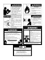
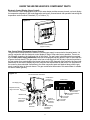
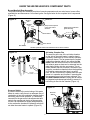
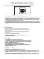
SERVICE HANDBOOK FOR
STANDARD RESIDENTIAL
HIGH EFFICIENCY ATMOSPHERIC VENT
(FVIR) GAS WATER HEATERS
MODELS:
GAHH 40 100,
GP 6 40YPC T 100,
PCG6240T403NOV 100,
PCG2J4040T3NOV 100,
12 40GPC T 100,
PCG2J4040T3NOV 100,
GAHH 50 100,
GP 6 50YPC T 100,
PCG250T403NOV 100,
PCG2J5040T3NOV 100,
12 50GPC T 100,
PCG2J5040T3NOV 100
Printed in U.S.A. 10/10
318181-000
1
ALL TECHNICAL AND WARRANTY QUESTIONS
SHOULD BE DIRECTED TO THE LOCAL DEALER FROM WHOM THE WATER HEATER WAS PURCHASED.
IF YOU ARE UNSUCCESSFUL, CONTACT A. O. SMITH WATER HEATERS RESIDENTIAL TECHNICAL ASSISTANCE
AT 1-800-527-1953 OR WWW.HOTWATER.COM.
2
SERVICE HANDBOOK
Your safety and the safety of others is extremely important in the servicing of this water heater. Many
safety-related messages and instructions have been provided in this handbook and on the water heater
to warn you and others of a potential hazard. Read and obey all safety messages and instructions
throughout this handbook. It is very important that the meaning of each safety message is understood
by you and others who service this water heater.
The information contained in this handbook is designed to answer commonly faced situations encountered in the operation of the standard Residential Gas product line and is not meant to be all-inclusive.
If you are experiencing a problem not covered in this handbook, please contact the Technical Information Center listed on the back of this handbook for further assistance. Additional information is also
available on the web site listed on the back of this handbook. This handbook is intended for use by
licensed plumbing professionals and reference should be made to the Installation Instructions and Use
& Care Guide accompanying the product. This handbook contains supplemental information to the
Installation Instructions and Use & Care Guide.
When servicing residential water heaters, it is essential that you return the unit to a safe condition
before you leave the site. All original components must be re-installed and all safety measures must be
implemented. In addition, the recommended water temperature setting is 120° F.
IMPORTANT: It is recommend that on every service call an inspection & cleaning of the air
intake chamber screen and combustion chamber and air diverter assembly be performed. See
page 24.
Tools Required (for servicing gas models):
• phillips head screw driver
• 3/8, 7/16, & 3/4 inch open end wrenches
• 3/16 inch Allen wrench
• 1-1/16 inch – 6 point – socket – for anode removal
• 5/16” nut driver
• pliers
• electrical multimeter (with alligator leads)
• digital or analog manometer
• gas pressure gauge
• Teflon® tape
• hose – to drain tank
Digital manometer shown.
Teflon ® is a registered trademark of E.I. Du Pont De Numours and Company.
3
Breathing Hazard - Carbon Monoxide Gas
Install vent system in accordance with
codes.
Do not operate water heater if flood
damaged
Heater should not be installed for High
Altitude operation above 10,100 feet
(3,078 m).
Do not operate if soot buildup.
Fire or Explosion Harzard
Do not store or use gasoline or other flammable vapors and
liquids in the vicinity of this or any other appliance.
Avoid all ignition sources if you smell Natural or LP gas.
Do not expose water heater control to excessive gas
pressure.
Use only gas shown on rating plate.
Maintain required clearances to combustibles.
Keep ignition sources away from faucets after extended
period of non-use.
Do not obstruct water heater air intake
with insulating jacket.
Do not place chemical vapor emitting
products near water heater.
Gas and carbon monoxide detectors
are available.
Read instruction manual before
installing, using or servicing
water heater.
Breathing carbon monoxide can cause brain damage or death.
Always read and understand instruction manual.
Improper installation and use may result
in property damage.
Do not operate water heater if flood damaged.
Install in location with drainage.
Fill tank with water before operation.
Be alert for thermal expansion.
Refer to instruction manual for installation and service.
4
TABLE OF CONTENTS
INTRODUCTION:
Service Handbook Introduction ...........................................................................................................................3
Warnings and Cautions .......................................................................................................................................4
Table Of Contents ...............................................................................................................................................5
INSTALLATION / OPERATION:
Basic Installation & Operation .............................................................................................................................6
Combustion Air and Vent System Requirements .......................................................................................... 7-10
KNOW YOUR WATER HEATER:
Know the Water Heater’s Component Parts ................................................................................................11-13
Water Heater Operation ....................................................................................................................................14
Filling and Draining the Water Heater ...............................................................................................................15
Lighting Instructions ..........................................................................................................................................16
ADJUSTING TEMPERATURE CONTROL:
Adjusting the Temperature on the Electronic Control Display ...........................................................................17
Using the Electronic Control Display ........................................................................................................... 18-19
Electronic Control Display Troubleshooting ................................................................................................ 20-23
COMPONENTS REMOVAL / REPLACING:
External Inspection and Cleaning .....................................................................................................................24
Electronic Control Display Removal / Replacement .........................................................................................25
Powered Anode Removal / Replacement ................................................................................................... 26-27
Pressure Switch Removal / Replacement .........................................................................................................28
Transformer Removal / Replacement ......................................................................................................... 29-30
Air Intake Chamber Box Removal / Replacement ...................................................................................... 31-33
Wiring Harnesss Removal / Replacement .................................................................................................. 34-36
Air Intake Chamber Fan Removal / Replacement ...................................................................................... 37-38
Pressure Tubing Removal / Replacement .................................................................................................. 39-40
Inner Door/Manifold/Burner Assembly Removal / Replacement ................................................................. 41-42
Flame Sense/Hot Surface Igniter Removal / Replacement ..............................................................................43
Burner Removal / Replacement .................................................................................................................. 44-46
Burner Orifice Removal / Replacement ...................................................................................................... 47-49
Gas Control Valve/Thermostat Removal / Replacement............................................................................. 50-52
CHECKPOINTS / GENERAL INFORMATION:
Checking the Gas Supply Pressure ..................................................................................................................52
Gas Water Heater Sizing Guide -and- Leakage Checkpoints .........................................................................53
General Information .................................................................................................................................... 54-55
5
BASIC INSTALLATION & OPERATION
INSTALLATION OF RESIDENTIAL GAS WATER HEATER
See Labels and
Installation Instructions
and Use & Care Guide
for clearances.
Exhaust Vent to
Ouside of Building
Union
Use Draft Hood
supplied with unit
Union
Untempered
Hot Water
Gas
Supply
Cold
Water
Inlet
*Massachusett: Install
a vacuum relief in cold
water line per section
19 MGL 142.
Expansion Tank
Pressurize to Equal
Supply Water Pressure*
(Relieve water pressure
on the expansion tank
before adjusting air
pressure.)
To Fixtures - Hot
Tempered Water
To Fixtures
Water
Shut-Off
Valve
Water
Supply- Cold*
Control
Display
Temperature-Pressure Relief Valve
with discharge piped to an
adequate drain. Do not cap or plug.
Manual Gas Shut-off Valve
Air Intake Chamber
Air is drawn in for combustion.
Keep area clean and free from
flammables and flammable vapors.
Hot
Water
Outlet
Gas Control Valve/Thermostat
Recommended setting of 120°F.**
Mixing Valve
(Set to 120°F)
Do not cap or plug.
Follow the Mixing Valve
Manufacturer’s Instructions
6” Maximum Air Gap
NOTE: Local codes
may vary.
Union
Sediment Trap
(Drip Leg) 3” Minimum.
Drain
Electrical Plug
Metal Drain Pan piped to an adequate drain.
NOTE: Drain pan diameter must be at least
2 inches wider than the diameter of the
water heater.
FV Sensor
Bracket
The water heater must be installed according to all local and state codes or in the absence of local
and state codes, the “National Fuel Gas Code”’ ANSI Z223.1(NFPA 54)- current edition.
* NOTE: If on a well system the expansion tank should be set to the maximum pressure of the pump tank.
** White-Rodgers® gas control valve/thermostat shown in this figure.
Figure 1
6
COMBUSTION AIR AND VENT SYSTEM REQUIREMENTS
Combustion Air Requirements:
Table 1:
WARNING
BTUH Input
Carbon Monoxide Warning
30,000
45,000
60,000
75,000
90,000
105,000
120,000
135,000
Water heater must be vented to outdoors.
Vent must be installed by a qualified technician using
the local and state codes or, in the absence of local
and state codes, the National Fuel Gas Code,
ANSI Z223.1 (NFPA 54) - current edition, and/or the
installation instructions.
Examples of a qualified technican include: gas
technicians, authorized gas company personel, and
authorized service persons.
Minimum Square
Feet with
8’ Ceiling
188
281
375
469
563
657
750
844
Typical Room
with 8’ Ceiling
9 x 21
14 x 20
15 x 25
15 x 31
20 x 28
20 x 33
25 x 30
28 x 30
IMPORTANT:
• The area must be open and be able to provide
the proper air requirements to the water
heater. Areas that are being used for storage
or contain large objects may not be suitable
for water heater installation.
• Water heaters installed in open spaces in
buildings with unusually tight construction may
still require outdoor air to function properly. In
this situation, outside air openings should be
sized the same as for a confined space.
• Modern home construction usually requires
supplying outside air into the water heater
area.
• Room exhaust fans may effect air
requirements.
Confined Space: For the correct and proper
operation of this water heater, ample air must be
supplied for the combustion, ventilation, and dilution of flue gases. Small enclosures and confined
areas must have two permanent openings so that
sufficient fresh air can be drawn from outside of
the enclosure. One opening shall be within 12
inches of the top and one within 12 inches of the
bottom of the enclosure.
The size of each opening (free area) is determined by the total BTUH input of all gas utilization
equipment (i.e., water heaters, furnaces, clothes
dryers, etc.) and the method by which the air is
provided. The BTUH input can be found on the
water heater rating plate. Additional air can be
provided by two methods:
1. All air from inside the building.
2. All air from outdoors.
Failure to so do can result in death or carbon monoxide
poisoning.
IMPORTANT: Air for combustion and ventilation
must not come from a flammable or corrosive atmosphere. Any failure due to flammable or corrosive elements in the atmosphere is excluded from
warranty coverage.
The following types of installation (not limited to
the following) will require outdoor air for combustion due to chemical exposure and may reduce
but not eliminate the presence of corrosive chemicals in the air:
• beauty shops
• photo processing labs
• buildings with indoor pools
• water heaters installed in laundry, hobby, or
craft rooms
• water heaters installed near chemical storage
areas
• water softeners
Combustion air must be free of acid-forming
chemicals such as sulfur, fluorine, and chlorine.
These elements are found in aerosol sprays, detergents, bleaches, cleaning solvents, air fresheners, paint, and varnish removers, refrigerants, and
many other commercial and household products.
When burned, vapors from these products form
highly corrosive acid compounds. These products should not be stored or used near the water
heater, air inlet, or air intake path.
Combustion and ventilation air requirements are
determined by the location of the water heater.
The water heater may be located in either an
open (unconfined) area or in a confined area or
small enclosure such as a closet or small room.
Confined spaces are areas with less than 50 cubic
feet for each 1,000 BTUH of the total input for all
gas-using appliances.
Unconfined Space: A water heater in an unconfined space uses indoor air for combustion and
requires at least 50 cubic feet for each 1,000
BTUH of the total input for all gas appliances. The
table below shows a few examples of the minimum square footage (area) required for various
BTUH inputs.
12” MAXIMUM
CLOSET
OR
OTHER
CONFINED
SPACE
PERMANENT
OPENINGS TO
THE OUTSIDE OR
ADDITIONAL
ROOMS WITHIN
THE BUILDING
12” MAXIMUM
Figure 2.
7
COMBUSTION AIR AND VENT SYSTEM REQUIREMENTS
All Air from Inside the Building: When
additional air is to be provided to the confined
area from additional room(s) within the building,
the total volume of the room(s) must be of
sufficient size to properly provide the necessary
amount of fresh air to the water heater and other
gas utilization equipment in the area. Each of the
two openings shall have a minimum free area
of 1 square inch per 1,000 BTUH of the total
input rating of all gas utilization equipment in
the confined area, but not less than 100 square
inches for each opening.
Minimum Free Area of Permanent Openings for
Ventilation and Combustion Air Supply - All Air from
Outdoors Only.
Based on total BTUH input rating for all utilizing
equipment within the confined space.
Opening Source
Minimum Free Area
Per Opening (sq. in.)
Reference
Drawing
*Direct to outdoors
1 sq. in, per 4000 BTUH
Figure 4
Vertical Ducts
1 sq. in, per 4000 BTUH
Figure 5
Horizontal Ducts
1 sq. in, per 2000 BTUH
Figure 6
Single Opening
1 sq. in, per 3000 BTUH
Figure 7
Example: A water heater with an input rating of 50,000 BTUH
using horizontal ducts would require each opening to have a
minimum free area of 25 square inches.
CONFINED
SPACE
Minimum free area = 50,000 BTUH x 1 sq. in. / 2000 BTUH = 25
sq. in.
These openings connect directly with the outdoors
through a ventilated attic, a ventilated crawl space, or
through an outside wall.
Consult the local codes of your area for specific
ventilation and combustion air requirements
*
PERMANENT
OPENINGS
1 SQUARE
INCH/1000
BTUH
(MINIMUM
100 SQ. IN.
FOR EACH
OPENING)
ABLE VENT
TO OUTDOORS
INSTALL ABOVE
INSULATION
Figure 3.
All Air from Outdoors: Outdoor fresh air can be
provided to a confined area either directly or by
the use of vertical and horizontal ducts. The fresh
air can be taken from the outdoors or from crawl
or attic spaces that freely communicate with the
outdoors. Attic or crawl spaces cannot be closed
and must be properly ventilated to the outside.
Ductwork must be of the same cross-sectional
area as the free area of the opening to which
they connect. The minimum dimension of
rectangular air ducts cannot be less than three
inches. The size of each of the two openings is
determined by the method in which the air is to
be provided. Refer to the table below to calculate
the minimum free area for each opening.
CONFINED
SPACE
OUTLET
AIR TO
ATTIC 1 SQ.
INCH PER
4000 BTUH
INLET AIR FROM
THE CRAWL SPACE
ALTERNATE
AIR INLET
1 SQ. INCH PER
4000 BTUH
100 SQ. INCH MINIMUM (EACH)
OPEN
FOUNDATION
VENT
ALL AIR FROM OUTDOORS: INLET AIR FROM VENTILATED
CRAWL SPACE/OUTLET AIR TO VENTILATED ATTIC
Figure 4.
Louvers and Grilles: In calculating free
area for ventilation and combustion air supply
openings, consideration must be given to the
blocking effect of protection louvers, grilles, and
screens. These devices can reduce airflow, which
in turn may require larger openings to achieve the
required minimum free area. Screens must not be
smaller than 1/4” mesh. If the free area through
a particular design of louver or grille is known, it
should be used in calculating the specified free
area of the opening. If the design and free area
are not known, it can be assumed that most wood
louvers will allow 20 - 25% of free area while
metal louvers and grilles will allow 60 - 75% of
free area. Louvers and grilles must be locked
open or interconnected with the equipment so that
they are opened automatically during equipment
operation. Keep louvers and grilles clean and free
of debris or other obstructions.
GABLE VENT
TO OUTDOORS
INSTALL ABOVE
INSULATION
OUTLET AIR TO
ATTIC 1 SQ. INCH
PER 4000 BTUH 100 SQ. INCH MIN.
(EACH)
CONFINED
SPACE
INLET AIR DUCT
1 SQ. INCH PER
4000 BTUH - 100
SQ. INCH MIN.
(EACH)
12” MAXIMUM
ALL AIR FROM OUTDOORS THROUGH VENTILATED ATTIC
Figure 5.
8
COMBUSTION AIR AND VENT SYSTEM REQUIREMENTS
Vent Connectors:
1. Type B, Double wall, U.L. Listed Vent Pipe.
2. Single wall Vent Pipe.
1 SQ. INCH PER
2000 BTUH
100 SQ. INCH
MINIMUM (EACH)
CONFINED
SPACE
Maintain the manufacturer’s specified minimum
clearance from combustible materials when using
type B double wall vent pipe.
Vent connectors made of type B, double wall
vent pipe material may pass through walls or
partitions constructed of combustible material if
the minimum listed clearance is maintained.
Maintain a one inch minimum clearance from all
combustible materials when using single wall vent
pipe.
OUTLET
OUTDOOR
AIR DUCTS
INLET
1 SQ. INCH PER
2000 BTUH 100 SQ. INCH
MINIMUM (EACH)
ALL AIR FROM OUTDOORS USING HORIZONTAL DUCTS
IMPORTANT: Single wall vent pipe cannot be
used for water heaters located in attics and may
not pass through attic spaces, crawl spaces or
any confined or inaccessible location. A single wall
metal vent connector cannot pass through any
interior wall.
Figure 6.
ALTERNATIVE
OPENING
LOCATION
When installing a vent connector, please note the
following
• Install the vent connector avoiding
unnecessary bends, which create resistance
to the flow of vent gases.
• Install without dips or sags with an upward
slope of at least 1/4-inch per foot.
• Joints must be fastened by sheet metal
screws or other approved means. It must be
supported to maintain clearances and prevent
separation of joints and damage.
• The length of the vent connector cannot
exceed 75% of the vertical vent height.
• The vent connector must be accessible for
cleaning, inspection, and replacement.
• Vent connectors cannot pass through any
ceiling, floor, firewall, or fire partition.
• It is recommended (but not mandatory) that
a minimum 12 inches of vertical vent pipe be
installed on the draft hood prior to any elbow
in the vent system.
IMPORTANT: Existing vent systems must be
inspected for obstructions, corrosion, and proper
installation.
1 SQ. INCH
PER 3000 BTUH
100 SQ. INCH
MINIMUM (EACH)
CONFINED
SPACE
ALL AIR FROM OUTDOORS - USING A SINGLE PERMANENT OPENING
Figure 7.
Vent Pipe System: This water heater must be
properly vented for the removal of exhaust gases
to the outside atmosphere. Correct installation of
the vent pipe system is mandatory for the proper
and efficient operation of this water heater and is
an important factor in the life of the unit.
The vent pipe must be installed according to all
local and state codes or, in the absence of local
and state codes, the “National Fuel Gas Code”,
ANSI Z223.1(NFPA 54)-current edition. The vent
pipe installation must not be obstructed so as
to prevent the removal of exhaust gases to the
outside atmosphere.
Chimney Connection: IMPORTANT: Before
connecting a gas vent to a chimney, make sure
the chimney passageway is clear and free of
obstructions. The chimney must be cleaned if
previously used for venting solid fuel appliances
or fireplaces. Also consult local and state codes
for proper chimney sizing and application or, in the
absence of local and state codes, the “National Fuel
Gas Code”, ANSI Z223.1(NFPA 54)-current edition.
• The connector must be installed above the
extreme bottom of the chimney to prevent
potentially blocking the flue gases.
U.L. recognized fuel gas and carbon monoxide
(CO) detectors are recommended in all
applications and should be installed using the
manufacturer’s instructions and local codes, rules,
or regulations.
Vent Pipe Size: It is important that you follow the
guidelines in these instructions for sizing a vent
pipe system. If a transition to a larger vent size is
required, the vent transition connection must be
made at the draft hood outlet. DO NOT reduce
the vent size to less than the draft hood outlet
diameter.
9
COMBUSTION AIR AND VENT SYSTEM REQUIREMENTS
•
•
•
The following figures are examples of vent pipe
system installations and may or may not be typical
for your specific application. Consult the “National
Fuel Gas Code”, NFPA 54, ANSI Z223.1-current
edition and the guidelines set forth by prevailing
local codes.
The connector must be firmly attached and
sealed to prevent it from falling out.
To aid in removing the connector, a thimble or
slip joint may be used.
The connector must not extend beyond the
inner edge of the chimney as it may restrict
the space between it and the opposite wall of
the chimney
3 FT.
Minimum
3 FT.
Minimum
2 FT. Minimum Above Any Object
Within 10 FT. Horizontally
Support Strap
Vent
Connector
Type B Double
Wall Vent Pipe
Maintain
Clearance*
Support Strap
Maintain
Clearance*
2 FT. Minimum Above
Any Object Within
10 FT. Horizontally
Seal
Do Not Extend
Vent Beyond Edge
Of Chimney
Vent
Connector
Slope Up
1/4 Inch
Per Foot
Minimum
Slope Up
1/4 Inch
Per Foot
Minimum
**Maintain
Specified
Clearance
Venting Gas Vent System With Type B Double Wall Vent Pipe.
Figure 9.
Chimney Termination Vent System
Consult the table found in the “National Fuel Gas
Code”, NFPA 54, ANSI Z223.1-current edition to
determine the minimum height from roof to lowest
discharge opening.
Figure 8.
Do not reduce the vent to less than the draft
hood outlet diameter. Do not terminate the vent
connector in a chimney that has not been certified
for this purpose. Some local codes may prohibit
the termination of vent connectors in a masonry
chimney.
Vertical Exhaust Gas Vent: Vertical exhaust
gas vents must be installed with U.L. listed type
B vent pipe according to the vent manufacturer’s
instructions and the terms of its listing.
It must be connected to the water heater’s draft
hood by a listed vent connector or by directly
originating at the draft hood opening.
Vertical gas vents must terminate with a listed cap
or other roof assembly and be installed according to
their manufacturer’s instructions.
Gas vents must be supported to prevent damage,
joint separation, and maintain clearances to
combustible materials.
IMPORTANT: This gas vent must be terminated in a
vertical position to facilitate the removal of the burnt
gases.
An unused chimney flue or masonry enclosure
may be used as a passageway for the installation
of a gas vent. NOTE: The chimney flue or masonry
enclosure size may be too large to allow proper
venting.
Common (combined) venting is allowable with
vertical type B vent systems and lined masonry
chimneys as long as proper draft for the water
heater is established under all conditions of
operation. CAUTION: DO NOT common vent this
water heater with any power vented appliance.
Listed Vent Cap
Maintain Manufacturer’s
Specified Minimum Clearance
Support Strap
Maintain
Clearance*
Seal
Vent
Connector
Slope Up
1/4 Inch
Per Foot
Minimum
**Maintain
Specified
Clearance
Vent Connector
Unused Chimney
Flue Or Masonry
Enclosure
Venting Through Chimney With Type B Double Wall Vent Pipe.
Figure 10.
* Maintain vent pipe clearance requirements to local,
state and/or the “National Fuel Gas Code”, ANSI
Z223.1(NFPA 54)-current edition.
** NFPA 211, Standard for Chimneys, Fireplaces,
Vents, and Solid Fuel-Burning Appliances states
that these chimneys are intended to be installed
in accordance with the installation instructions
provided with each chimney support assembly.
Minimum air space clearance to combustible
materials should be maintained as marked on the
chimney sections.
10
KNOW THE WATER HEATER’S COMPONENT PARTS
Electronic Control Display (Upper Control)
The Electronic Control Display panel used on this water heater provides an easy-to-read, eye level display
for temperature adjustment, fault code diagnostics and recall, powered anode rod operation and setting the
temperature scale for either Fahrenheit (°F) or Celsius (°C).
Figure 11.
Electronic Control Display
(Upper Control)
Gas Control Valve/Thermostat (Lower Control)
The gas control valve/thermostat is where the incoming gas supply is connected to the water heater. It is
used in conjunction with the electronic control display to start or stop main burner operation. There is an
On/Off switch located on the right-hand side of the control. The gas control valve/thermostat is energized
by a 24 VAC power supply transformer and uses a temperature sensing probe to open or close the flow
of gas to the main burner. The gas control valve has an inlet filter built into its body to prevent impurities in
the gas system from contaminating the internal valves and a LED diagnostic light located in the lower right
hand corner of the valve to display any micro-computer fault experienced by the control. On the bottom of
the control is where electrical connections to the other component parts are attached along with the gas
supply (manifold tube) to the main burner. The gas control/valve thermostat of this water heater is suitable
for use on Natural gas only.
Figure 12.
Gas Control Valve/ Thermostat
On/Off Switch
located on
the right side.
Bottom View
Gas Supply- Inlet
Temperature Probe
/High Limit Probe
1 8 Pin Systems
Connector
2 5 Pin Communications
Connector
Manifold Tube
Power Supply 4
Transformer
Connector
3 3 Pin Ignitor
Pressure
1 Switch / Fan,
FV Sensor
Connector
3
Igniter/Flame
Sense
Connector
2
Control Display,
Anode Rod
Connector
11
Connector
4 2 Pin Power
Connector
KNOW THE WATER HEATER’S COMPONENT PARTS
Burner/Manifold Door Assembly
The burner/manifold door assembly consists of several components such as: main burner, burner orifice,
manifold tube and flame sense / hot surface igniter. See figure below for the complete list of components
(Figure 13).
Figure 13.
Main Burner
Manifold
Tube
Manifold
Door
View
Port
Scoop side to be placed
on the same side as
View Port.
Flame Sense / Hot Surface
Igniter Assembly
Burner Orifice*
Flame Sense/
Hot Surface
Igniter Assembly
Burner Screws
Door Gasket
*DO NOT operate the water heater without the burner orifices installed.
Figure 14.
Air Intake Chamber Fan
The small fan at the top of the air intake chamber
on the side of the water heater is used to draw in
necessary combustion air for the efficient operation
of the main burner. The fan pressurizes the sealed
combustion chamber which in turn allows the flue
baffle inside the center flue tube to slow down the
hot exhaust gases so heat can be extracted into the
water before exiting into the vent system. The air
intake chamber fan runs for about 5 seconds to prepurge the combustion chamber before the beginning
of an ignition sequence when there is a call for
heat. The fan will continue to operate while the main
burner is in operation and for about 5 seconds after
the temperature set point has been achieved. The
air intake chamber screen covering the fan should
be inspected and cleaned periodically to assure it is
not limiting air flow into the chamber (Figure 14).
Air intake
Chamber
Screen
Air intake
Chamber
Fan
Air intake
Chamber
Figure 15
Pressure Switch
A pressure switch in the control string of this water
heater is used to verify there is an adequate flow of
combustion air into the combustion chamber before
and during main burner operation. It is electrically
connected to the gas control valve/thermostat and
controls the opening and closing of the gas valve.
If there is an insufficient air supply being delivered
to the combustion chamber the pressure switch will
not allow the water heater to operate (Figure 15).
Pressure
Switch
12
KNOW THE WATER HEATER’S COMPONENT PARTS
Figure 16.
Flammable Vapor Cut Off Switch (FV Sensor)
The water heater is equipped with a FV sensor, for
detecting the presence of flammable vapors (e.g.
spilled gasoline). When the sensor detects those
vapors, the heater will shut down and not operate.
If flammable vapors are detected or the sensor
is inoperative, an icon will flash on the electronic
control display and the heater will go into a lockout
mode. The water heater will not function again until
the flammable vapors have been eliminated and the
control is manually reset using a special Flammable
Vapor sensor reset sequence. (Figure 16).
FV Sensor
Figure 17.
Power Anode Rod
To protect the glass-lined water tank from corrosion
through electrolysis, this water heater is equipped
with a non sacrificial powered anode rod. Unlike
conventional magnesium or aluminum anode rods
used in water heaters, the powered anode does
not deteriorate and is less likely to contribute to
the occurrence of “Smelly (Rotten Egg) Water”
(Figure 17).
Powered
Anode
Rod
HOW THE WATER HEATER’S COMPONENT PARTS ARE CONNECTED
Figure 18.
Air Intake
Chamber Fan
Gas Control
Valve / Thermostat
Anode
Rod
Pressure
Switch
Control Display
CAUTION:
DO NOT USE AN EXTENSION
CORD TO CONNECT THE
TRANSFORMER TO AN
ELECTRICAL OUTLET.
Igniter/Flame
Sense Connector
FV
Sensor
CAUTION:
LABEL ALL WIRES PRIOR TO
DISCONNECTION WHEN SERVICING
CONTROLS. WIRING ERRORS CAN CAUSE
IMPROPER AND DANGEROUS OPERATION.
VERIFY PROPER OPERATION AFTER SERVICING.
13
Power Supply
Transformer
WATER HEATER OPERATION
The figure below shows the water heater’s sequence of operation when a call for heat is initiated. The gas
control valve/thermostat will attempt to light the burner three times. If the flame sense rod in the burner/
manifold assembly does not detect ignition, the control will enter lockout mode indicated by the electronic
control display’s flashing of the appropriate status code.
SEQUENCE OF OPERATION
Call for heat indicated by
flashing of display screen
status codes.
Gas valve/thermostat will open
for 4 second trial for ignition
and fan will turn on.
Gas valve/thermostat will do a
relay check (relay clicks will be
heard).
Main burner flame is detected by
flame sense rod. Air intake fan
and main burner will continue to
operate until water temperature
inside the tank reaches
temperature set point.
Display will show temperature
set point during call for heat.
Gas valve/thermostat is deenergized and air intake fan
continues for a post purge time
of approximately 5 seconds.
Draft Blower is energized.
System will verify pressure
switch operation and start a
5 second pre-purge, then air
intake fan will turn off.
Water heater returns to standby
mode.
Ignitor will start a 12 second
warm up period. “IGN” will
show on display.
14
FILLING, DRAINING AND FLUSHING THE WATER HEATER TANK
It is recommended that the tank be drained and flushed every 6 months to remove sediment which
may build up during operation. The water heater should be drained if being shut down during freezing
temperatures. To drain t