1
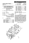
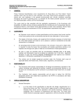
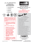
FEATURES
84% THERMAL EFFICIENCY – The absolute highest thermal
efficiency possible by a non-condensing boiler is achieved by
the new Genesis Boiler.
Low NOx –Precise amounts of gas and air are premixed through
special Pre-Jet Orifices and forced through stainless steel
burners that provide complete and clean combustion. Meets or
exceeds California SCAQMD air quality standards.
HOT WATER SUPPLY BOILERS
MODELS GW/GWO-1000 THRU GW/GWO-2500
EXCLUSIVE DIA-SCAN II W/STAGED FIRING – The Dia -Scan II is
a complete microprocessor based boiler control. Every electrical
boiler function; from starting the pump, to stage firing the main
burner, to cycling the pump off at the end of a heating cycle; is
controlled and monitored by the onboard computer. A
comprehensive display panel includes LEDs that indicate
current operating and fault status. A digital LED displays
temperature set points, outlet temperature, current inlet/outlet
differential (∆T), tank temperature, and additional numerical fault
codes. Precise temperature management is plus or minus 1°.
In addition, the Dia-Scan II provides true self-diagnostic
capabilities, eliminates guesswork, and reveals exactly where
the problem is. Troubleshooting has never been easier.
ASME
CRN
STAGED FIRING – All second family Genesis boilers are staged
fired. The boiler automatically adjusts its firing rate and btu
output to maintain precise system temperature control. Each
stage is user programmable; allows the boiler to be tailored to
the installation and adjusted for optimum boiler performance
and overall system efficiency. Models GW-1000 thru GW-1500
have three stages; Models GW-1850 thru GW-2500 have four
stages.
HEAT EXCHANGER
HEAVY-DUTY CAST HEADERS – Choose from heavy non-ferrous
all bronze headers or heavy cast iron Cora-Shield Coated
headers. Genesis boiler headers are split bolted designs that
allow complete and easy inspection of all internal header water
surfaces and easy inspection of the copper tubes.
HIGH EFFICIENCY HIGH HEAT TRANSFER – A.O. Smith’s
distinctive double row integral finned copper heat exchanger
provides maximum heat transfer and utilizes a self-baffling
staggered tube design, that assures 84% thermal efficiency.
INTEGRAL REAR HEADER BOILER MOUNTED PUMP – Factory
sized and integrally rear header mounted, pre-wired bronze fitted
pump is standard. Dia-Scan II controlled pump time delay allows
the removal of useable residual heat from the combustion
chamber during the stand-by cycle. Practically eliminates standby heat loss.
FACTORY TESTED – Each Genesis boiler is water and fire tested
before leaving the factory
UNMATCHED VENTING FLEXIBILITY – Multiple venting options;
choose from several conventional or direct venting options.
Multiple openings options; choose from exhaust outlet leaving
the top of boiler or exhaust outlet-leaving the rear of boiler.
STACKABLE SPACE SAVING DESIGN – Up to 5 million btu's in
the space of a 2.5 million btu boiler.
OTHER FEATURES
ASME Pressure Relief Valve 125# • Mounted Flow Switch
• Remote Tanks Temperature Sensor • Alternate Thermostat
Terminals (24V) • Manual Reset High Limit • Blocked Flue
Switch • Fan Proving Switch • Adjustable Pump Delay.
Revised March 2003
OPTIONS
Code Options: CSD-1, California Code, IRI,
New York, and Illinois School Code.
•
•
•
•
•
•
•
•
•
•
Alarm Bell
Outdoor Models
Stack Rack
Low Water Cut Off
Extended Power Venting Kits
Dry Contacts For Any Boiler Failure
Direct and Sidewall Vent Terminal Kits
Cupro-Nickel Tubes
Hard Water Pump (inline)
Sequencing Control Panel (2-8 Boilers)
LIMITED WARRANTY OUTLINE
If the heat exchanger should fail within 5 years, under
the terms of the warranty, A.O. Smith will furnish a
replacement part; installation, labor, handling and local
delivery extra. THIS OUTLINE IS NOT A WARRANTY.
For complete information, consult the written warranty
or A.O. Smith Water Products Company.
Warranty does not apply to product installed outside of the
United States of America or its territorial possessions and
Canada.
A 012.15
AIR INLET
G
ALTERNATE EXHAUST
A
17"
C
FLOW
SWITCH
D
F
ELECTRICAL
CONNECTIONS
31 3/4"
OUTLET/ECO
TOP VIEW
CONTROL BOX CONTAINING
CCB AND ICB BOARDS
5 7/16"
GAS INLET
B
E
14 1/2"
INLET
TEMP.
PRESSURE RELIEF VALVE
Model
GW-1000
GW-1300
GW-1500
GW-1850
GW-2100
GW-2500
Water
Connections
2 1/2
2 1/2
2 1/2
2 1/2
2 1/2
2 1/2
Gas
Connections
2
2
2
2 1/2
2 1/2
2 1/2
Vent
10
12
12
14
14
16
Inlet Air
8
10
10
12
12
14
All Dimensions in Inches
A
Width
B
WO/Pump
Height
C
47
40 1/2
14
57 1/2
40 1/2
24 3/4
64 1/2
40 1/2
30
78 3/4
43 1/4
27 3/4
85 1/2
43 1/4
31
99 1/2
43 1/4
38
D
12 1/2
12 1/2
12 1/2
11 1/2
11 1/2
11 1/2
E
36 1/4
36 1/4
36 1/4
35 1/4
35 1/4
35 1/4
F
31 3/4
31 3/4
31 3/4
32 1/2
32 1/2
32 1/2
G
20 3/4
16 1/2
18
34 1/4
33 1/2
36 1/4
Width
W/Pump
64
74 1/2
81 1/2
95 3/4
102 1/2
116 1/2
Maximum gas supply pressure is 13.8" W.C. for both Natural and Propane Gas.
The minimum supply gas pressure is 7" W.C. for Natural Gas.
The minimum supply gas pressure for Propane is 11.0" W.C.
Requires: 120V, 60 Hz, 30 Amps.
HOT WATER SUPPLY BOILER RECOVERY CAPACITIES
Temperature Rise -Degrees F. Gallons Per Hour
Model
GW-1000
GW-1300
GW-1500
GW-1850
GW-2100
GW-2500
Input Rating BTU/Hr.
Natural &
Propane (LP) Gas
990,000
1,300,000
1,500,000
1,850,000
2,100,000
2,490,000
GPH
GPH
GPH
GPH
GPH
GPH
40
2520
3309
3818
4709
5345
6338
50
2016
2847
3055
3767
4276
5071
60
1680
2208
2545
3139
3564
4225
70
1440
1891
2182
2691
3055
3622
60
1260
1655
1909
2355
2673
3169
90
1120
1471
1697
2093
2376
2817
100
1008
1324
1527
1884
2138
2535
110
918
1203
1388
1712
1944
2305
120
840
1103
1273
1570
1782
2113
130
775
1018
1175
1449
1645
1950
Genesis BTU Input/Output And Flow Rates
BTU Input/Output
Boiler Rate of Flow and Pressure Drop
Input Rating BTU/Hr. Output Rating BTU/Hr. 20 Deg. F Rise 30 Deg. F Rise 40 Deg. F Rise Maximum Flow Rate Minimum Flow Rate
Natural &
Natural &
PD-Ft.
PD-Ft.
PD-Ft.
PD-Ft. Deg.F
PD-Ft. Deg.F
Model
Propane (LP) Gas
Propane (LP) Gas GPM Head GPM Head GPM Head GPM Head
Rise GPM Head Rise
GW-1000
990,000
831,600
83
5.1
55
2.7
42
1.5
154 12.2
11
42
1.5
40
GW-1300
1,300,000
1,092,000
109
72
73
4.2
55
3.2
154 14.5
14
55
3.2
40
GW-1500
1,500,000
1,260,000
126
10.1
84
8.3
83
4.3
154 16.3
17
64
4.3
40
GW-1850
1,650,000
1,554,000
154
19
104
10.1
78
6.4
154 16.5
20
78
6.4
40
GW-2100
2,100,000
1,764,000
N/A
N/A
116
14.5
68
8.3
154 21.3
23
89
8.3
40
GW-2500
2,490,000
2,091,600
N/A
N/A
139
16.5
105
11.6
154 23.2
26
106 11.6
40
Note: Flow rates and pressure drops shown above are through the boiler only and include no field piping. The field piping must also be
considered when sizing system pumps.
Note: The standard factory supplied internal rear header mounted pump is sized for the boiler and up to additional 50 equivalent feet
of field piping.
A 012.16
A
31.59
OUTDOOR MODELS
18.25
MODEL
DIM. "A" DIM. "B"
GWO-1000
66.00
58.67
GWO-1300
76.50
58.67
GWO-1500
83.50
58.67
GWO-1850
97.50
61.37
GWO-2100 104.50
61.37
GWO-2500 118.50
61.37
B
18.07
17.39
DIRECT VENT (HORIZONTAL)
DIRECT VENT (VERTICAL)
Model
GW-1000
GW-1300
GW-1500
GW-1850
GW-2100
GW-2500
Vent Size
10'
12'
12'
14'
14'
16'
Combustion
Air Intake
8'
10'
10'
12'
12'
14'
DIRECT VENT (VERTICAL)
SIDEWALL VENTING
Natural Draft
Max. Distance W/O
Barometric Damper / With
Barometric Damper
35’ / To Roof
35’ / To Roof
35’ / To Roof
35' / To Roof
35' / To Roof
35' / To Roof
Sidewall
Venting*
70'
70'
70'
35'
35'
35'
Sidewall Venting
W/Opt. Extended Vent
Kit (Power Assisted)
110'
110'
110'
110'
110'
110'
DIRECT VENT (HORIZONTAL)
NATURAL DRAFT
Direct Vent*
35’ / 35'
35’ / 35'
35’ / 35'
15' / 15'
15' / 15'
15’ / 15'
Direct Vent
W/Opt. Extended Vent
Kit (Power Assisted)
60’ / 60'
60’ / 60'
60’ / 60'
60' / 60'
60’ / 60'
60’ / 60'
See installation manual for additional venting information further details.
Notes: * Maximum three elbows
** Maximum two elbows -each- lntake/Exhaust
90/45 degree elbows are equivalent to 10/5 feet of vent pipe respectively.
All venting configurations terminating horizontially are Category III and require AL29-4C venting material.
All venting configurations terminating vertically are Category I and can use type B venting material (Except where local codes require
AL29-4C sealed venting material.)
A 012.17
SUGGESTED SPECIFICATIONS
The hot water supply boiler(s) shall be an A.O. Smith Genesis Model GW _________ having an input rating of ________ BTU/hr,
and an output rating of ________ Btu/hr when fired with (Natural/Propane) _________ gas. The boiler shall bear the ASME “H”
stamp and shall be National Board registered (CRN in Canada) for 160 PSI working pressure. The boiler(s) shall be equipped
with a factory installed 125 PSIG ASME Pressure Relief Valve.
The boiler(s) shall be design tested and certified to the ANSI Z21.13 standard and approved by the American and Canadian Gas
Associations with a listed thermal efficiency of 84%.
The boiler’s copper fin tube heat exchanger shall be a horizontal, double row, two pass, 15-tube design. The lower first pass with
8 solid copper tubes, shall have integral extruded copper fins spaced at “5” fins per inch, the upper second pass with 7 solid
copper tubes shall have “7” extruded copper fins per inch. The tubes shall be rolled into heavy (all Bronze “Standard” /or Cast Iron
CoraShield lined ”optional”) ___________________headers. The ASME approved bolted split headers must have a removable
faceplate that allows full access and inspection of the tubes and internal header surfaces. Non-removable one-piece headers,
with small inspection plugs, shall not be acceptable.
The heat exchanger shall bear a 5-year manufacturer’s limited warranty against failure. The heat exchanger shall be immune to
thermal shock.
The Boiler(s) shall be provided with the factory sized, integrally rear header mounted, pre-wired, bronze fitted, factory installed
pump. The pump shall be controlled by the boiler’s Dia-Scan II control and include an adjustable time delay, that allows the
removal of useable residual heat from the combustion chamber and cools the boiler to an equal system temperature during the
stand-by cycle.
The combustion chamber shall be fully lined with lightweight, high temperature ceramic fiber insulation, rated to 2,300°F (1260°C).
The jacket panels shall be powder coated with a baked-on finish, which is suitable for outdoor service. The jacket shall be of tight
construction, and weather and water-resistant.
The boiler shall employ a fan induced premixed multi-burner system firing into a pressurized combustion chamber. The “4509”
stainless steel/titanium alloy burners shall be fired using Pre-Jet gas orifices that provide precise gas to air mixture for clean
combustion and low NOx operation. The pre-Jet gas orifices shall be self-adjusting for altitude, from sea level to 6,000 feet
(1,830m). The boiler(s) shall be capable of meeting or exceeding the current national, state, and local air quality regulations for low
NOx.
All electrical boiler functions shall be controlled, operated, and monitored by a Dia-Scan II microprocessor-based control. The DiaScan II control shall provide (three “GW-1000 thru GW-1500”/four “GW-1850 thru GW-2500) _____ stage operation. Each stage
shall be adjustable by the operator to allow the boiler to be adjusted to suit the application and maximize system/boiler efficiency
and operation. The microprocessor shall control the boiler temperature and be accurate to within plus or minus 1°F. The hot
surface ignition system shall employ a separate flame sensor for each stage to provide maximum safety. The microprocessorbased boiler control shall be tested to ANSI standards and approved by both UL and AGA/CSA.
The boiler shall be supplied with a remote tank thermistor for sensing and controlling the storage tank temperature up to 1,000 feet
(300m) away by the Dia-Scan II boiler control. Alternate 24V contacts shall also be provided to allow the boiler to be controlled by
energy management systems and/or multi-boiler controllers.
The microprocessor-based control shall be self-diagnostic and provide 25 LED’s that indicate current operating and fault status.
In addition to the LED’s, a digital LED enunciator shall provide numerical read outs of inlet/outlet, inlet/outlet differential, set point
and set point differential temperatures; along with additional numerical failure codes.
Factory mounted and wired flow, blower prover, and blocked flue switches shall be provided. The gas train shall meet or exceed the
requirements of ANSI Z21. 13 and include gas pressure regulator, manual gas cock, redundant safety gas valve, operating control
valve, and plugged pressure test tapings.
The boiler(s) shall be AGA/CSA approved for direct horizontal through the wall venting, or direct vertical venting; in addition to
conventional sidewall or conventional vertical venting. The boiler(s) must be field convertible from top mounted venting to rear
mounted venting.
For maximum floor space optimization, the boiler(s) will have the option of being stacked directly one above the other using a
factory designed Stack-Rack as provided by the manufacturer. Boilers with top only vent outlets that cannot be stacked directly one
above the other are not acceptable.
A. O. Smith
Water Products Company
Ashland City, TN
A Division of A. O. Smith Corporation
A.O. Smith Water Products Co., Inc. On Line
w w w.hotwater.com
For Technical Information and
Automated Fax Service,
Phone: 800-527-1953
A 012.18
A. O. Smith Corporation reserves the right to make product changes
or improvements at any time without notice.
© A. O. Smith Corp., 2003
Printed in U.S.A.