1
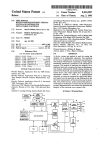
‘
United States Patent 1191
Us005786584A
[11] Patent Number:
[45] Date of Patent:
Button et al.
[54] VIAL AND CARTRIDGE READING DEVICE
4,882,475
5,019,974
5,088,056
PROVIDING AUDIO FEEDBACK FOR A
BLOOD GLUCOSE MONITORING SYSTEM
[75] Inventors: Timothy Hemenway Button.
Indianapolis; Scott Forster Percy.
Carmel. both of Ind.
11/1989 111111616141. .......................... .. 235/383
5/1991 Becker's .......... ..
128/920x
2/1992 MCInlOSIl et a1.
5,091,634
2/1992
5,291,399
3/1994
..... .. 364/569
..
235/375
235/375 x
5,357,095
10/1994
5,371,687
12/1994 Ho1mes,Ilet a1. ..
5,401,110
5,597,995
5,663,545
[73] Assignee: Eli Lilly and Company. Indianapolis.
5,786,584
Jul. 28, 1998
.
235/3752:
.... .. 364/514
3/1995 Neeley ............... ..
235/375x
1/1997 Williams et a1.
.... .. 235/375
9/1997 Marquiss ............................... .. 275/375
Ind.
[21] Appl. No.: 699,766
Aug. 20, 1996
[22] Filed:
.............................. .. G06K 7/10
[5 1] 1111. (:1.6 ..
[52] vs. c1. ........................ .. 235/462; 235/375; 235/385;
235/472; 235/486
[5 8]
Primary Examiner—Donald T. Hajec
Assistant Examiner—Michael G. Lee
Attorney, Agent, or Firm—Michael T. Bates; David E.
Boone
[57]
ABSTRACT
A device for reading the labeled contents of an insulin
Field of Search ................................... .. 235/462. 375.
container and then providing an audible message informing
235/385. 435. 439. 454. 470. 472. 486;
395/28; 128/920. 921; 422/64. 65. 66.
67. 102. 104; 250/234. 566.568
the user of the labeled contents. The device includes a
recessed surface. such as a cylindrical well. into which an
References Cited
[56]
U.S. PATENT DOCUMENTS
4,164,320
4,476,381
4,622,457
4,692,308
4,729,661
4,760,245
4,831,562
8/1979 Irazoqui et a1. ...................... .. 235/375
10/1984
'
235/375
11/1986
.. 235/464
9/1987
3/1988
7/1988
422/65
5/1989
356/437
235/379
McIntosh et a1.
insulin container is insertable by a vision impaired person.
An optical scanner or reader reads a code furnished as part
.................... .. 564/569
of the labeling on the inserted insulin container. A micro
computer compares the read code to known code patterns
and a speech output is generated as to the type of insulin
within the container. The speech output is broadcast over a
speaker so as to be audible to a listener. The device may be
integrated into a blood glucose sensor. or furnished in a unit
that may assemble to an existing blood glucose sensor.
19 Claims, 15 Drawing Sheets
US. Patent
Jul. 28, 1998
Sheet 1 of 15
5,786,584
US. Patent
Jul. 28, 1998
Sheet 4 of 15
5,786,584
0_QD< PDnE O Q5 3
31)
Q
a26;.
G
‘.l'? l
m
.5
.wE
wa
an
“HA/ml“.
umc<hozmu o
:5
UK
M5238
i;
~_
@.wE
by“
an
US. Patent
Jul. 28, 1998
1:81:
Fig. 7
Sheet 5 of 15
5,786,584
US. Patent
Jul. 28, 1998
,55
Sheet 8 of 15
5,786,584
/? 15a
-
i
If ;
Fig. 10
152
US. Patent
Jul. 28, 1993
Sheet 9 of 15
5,786,584
I60
"K "Wu. """m
it
US. Patent
Jul. 28, 1998
Sheet 10 of 15
5,786,584
US. Patent
Jul. 28, 1998
Sheet 11 of 15
5,786,584
US. Patent
Jul. 28, 1998
Sheet 12 of 15
200
'
5,786,584
/
/
z
W
Fig. 14
US. Patent
Jul. 28, 1998
Sheet 13 of 15
5,786,584
US. Patent
Jul. 28, 1998
Sheet 14 of 15
5,786,584
US. Patent
Jul. 28, 1998
Sheet 15 of 15
5,786,584
5.786.584
2
1
Thus. it is desired to provide a device which aids the
VIAL AND CARTRIDGE READING DEVICE
PROVIDING AUDIO FEEDBACK FOR A
BLOOD GLUCOSE MONITORING SYSTEM
vision impaired patient in choosing the correct insulin
container for insulin injection.
SUMMARY OF THE INVENTION
CROSS REFERENCE TO RELATED
APPLICATION
This application claims the bene?t under 35 U.S.C. §
119(e) of United States Provisional Application Ser. No.
60/003328. ?led Sep. 6. 1995.
BACKGROUND OF THE INVENTION
The present invention pertains to blood glucose sensors or
monitors for analyzing a blood droplet and outputting to the
user a blood glucose reading. and. in particular. to a blood
glucose sensor having an audio feedback.
Blood glucose sensors are well known in the art. Recently.
sensors have been developed to include audio output to aid
The present invention provides a voice synthesizer device
allowing a visually impaired person or diabetic to indepen
dently determine the contents of insulin containers. The
device ?rst identi?es the labeled contents of an insulin
container. and then generates an audible message to inform
10 the user of the contents. The insulin container includes a
readable code. such as a bar code. on its label. When the bar
code is read by an optical scanner in the device. a voice
synthesizer coupled to a speaker in the device produces an
audible message to a user as to the contents of the insulin
container. The device may be integrated into a blood glucose
sensor. or provided in a unit that assembles to an existing
blood glucose sensor.
In one form thereof. the present invention provides a
patients in monitoring their own glucose levels despite their
vision loss. Such sensors have been called talking glucom
eters. One leading sensor is commercially available from
Boehringer Mannheim Diagnostics. Inc.. Indianapolis. Ind..
device for identifying a labeled content of a medication
20
modate a container containing a medication. a reader
arranged to read a medication identifying code on the
under the trade name Accu-Chek® 11 Freedom System. In
this device. a user deposits a drop of blood onto a test strip
pad with the aid of a ?nger guide. The device optically
senses the blood and outputs the audio instruction “Press the
timer button." After the timer button has been pushed. a
25
visual and audio blood glucose reading is communicated to
the patient. The entire system is housed in a single unit.
Another audio blood glucose monitoring system is commer
an audible message to a user of the device.
N.J.. under the trade name Diascan Partner. Like the Accu
In another form thereof. the present invention provides an
Chek® II. this system is housed in a single unit and includes
insulin label reading device including a body. which is either
a voice module for providing messages on calibration and
con?gured as an adaptor into which a separate portable
blood glucose sensor removably inserts or con?gured as a
glucose readings.
35
their own natural glucose curves over the course of a day.
For example. Lilly produces Humulin® R. Humulin® N.
Humulin® L. Humulin® U. Humulin® 50/50. and Humu
lin® 70/30. A container of Lilly insulin typically includes a
40
housing into which a portable blood glucose sensor is
integrated. means. within the body. for reading an insulin
identifying code on an insulin container. and means. cir
cuited to the code reading means. for providing an audible
message to a user identifying a type of insulin labeled by the
code as within the container.
In still another form thereof. the present invention pro~
bar code on its label known as the “pharma code". This bar
code is part of one type of internal security check which may
be used in the manufacturing process to ensure that a speci?c
label matches the contents of the container on which the
container when the container is positioned at the body
portion. a controller within the body and circuited to the
reader to receive a signal from the reader corresponding to
the read code. wherein the controller compares the signal to
stored data. a voice synthesizer for generating a speech
pattern identifying the medication in the container respon
sive to the controller comparing the signal and stored data.
and a speaker for broadcasting the speech pattern to provide
cially available from Home Diagnostics. Inc.. Eatontown.
Eli Lilly and Company (“Lilly”). a world leader in the
production of insulin products. produces a number of dif
ferent types of insulin to enable patients to better simulate
container including a body with a portion shaped to accom
vides the combination of a medication container which
includes a code arranged on a portion of an exterior con
tainer surface. and a device for identifying a labeled content
45
of the medication container. The device includes a body
label is a?ixed. Prior to the label being applied to a given
container. the manufacturer scans the bar code to verify that
including a portion complementarily shaped to the medica
an appropriate labeling is occurring.
Each of the Lilly insulin products is designed for a
particular glucose level and for a particular duration. Often.
container when the container is positioned at the portion. a
controller within the body and circuited to the code reader to
receive a signal from the code reader corresponding to the
read code. wherein the controller compares the signal to
stored data. a voice synthesizer for generating a speech
pattern identifying the medication in the container respon
sive to the controller comparing the signal and stored data.
tion container. a code reader arranged to read the code on the
a patient will inject himself/herself with one insulin product
in the morning and a dilferent insulin product in the after
noon and/0r evening. Serious adverse medical consequences
could occur if a patient mistakenly grabs the wrong insulin
container and injects himself/herself with the wrong insulin
product (e.g. Humulin® R instead of Humulin® U).
Accordingly. it is important that the patient choose the
55
One advantage of the present invention is that an audible
correct insulin container for use at a given time.
message as to the labeled contents of a medication containm
The selection of the correct insulin container is generally
is provided.
not a problem for those individuals having good eyesight
Another advantage of the present invention is that its
user-friendly design allows its use by a person with impaired
and who can easily read the label on the container. However.
for those individuals with limited or no vision. a greater risk
vision to independently determine the labeled contents of a
medication container.
exists that a misreading or a failure to read the label on the
container will occur. which in turn may result in an inad
vertent selection of a wrong container. Because impaired
vision is often a result of diabetes. this problem can be
signi?cant.
and a speaker for broadcasting the speech pattern to provide
an audible message to a user of the device.
65
BRIEF DESCRIPTION OF THE DRAWINGS
The above mentioned and other advantages and objects of
this invention. and the manner of attaining them. will
5,786,584
3
4
become more apparent and the invention itself will be bettq
this system embodiment. base unit 30 serves as a voice
understood by reference to the following description of
synthesizer adaptor which furnishes an existing sensor prod
embodiments of the invention taken in conjunction with the
uct with the inventive features of first identifying the labeled
accompanying drawings. wherein:
contents of an insulin container and then broadcasting an
audible message to a user as to the identity of the contents.
FIG. 1 is a perspective view of a ?rst embodiment of the
present invention in which a blood glucose monitor is
removably housed within a base unit including a vial and
The con?guration of sensor 27 shown in FIG. I and in the
additional embodiments conforms to the Accu-Chek®
AdvantageTM blood glucose monitor. which is commercially
available from Boehringer Mannheim Corporation of 1nd.
cartridge reader of the present invention;
FIG. 2 is a plan view of the embodiment of FIG. 1 with
the monitor shown removed. and wherein selected internal
Indiana. Except as further explained below. additional detail
regarding the AdvantageTM type monitor and the associated
components contributing to the container reading and audio
test strips are not necessary for an understanding of the
present invention. and therefore are omitted herein. Such
detail can be found in the User's Manual for the Advan
tageTM type monitor and US. Pat. Nos. 4.963.814. 4.999.
output functions are diagrammatically shown in dashed
lines;
FIG. 3 is a diagrammatic side view of the embodiment of
FIG. 1. wherein select portions of the invention are shown
582. 4.999.632. and 5.243.516. which are all incorporated
in dashed lines;
FIG. 4 is a diagrammatic front view illustrating the
placement of bar codes on different types of insulin con
tainers; FIG. 5 is a front view of an example of a bar code
for a container label;
herein by reference.
It will be appreciated that with appropriate modi?cation.
base unit 30 can be adapted to function with other types of
20
Alternatively. rather than being provided within an acces
sory or separate component which retro?ts existing monitors
FIG. 6 is a general block diagram of the code scanning
and audio output functions of the present invention;
FIG. 7 is a plan view of a second embodiment of a blood
glucose monitoring system of the present invention;
25
FIG. 8 is a plan view of a third embodiment of a blood
glucose monitoring system of the present invention;
FIG. 9 is a diagrammatic side view of the system of FIG.
8. wherein some of the internal components and inserted
containers are diagrammatically shown in dashed lines;
FIG. 10 is a front perspective view of a fourth embodi
Blood glucose monitoring system 25 will be further
invention;
35
of a blood glucose monitoring system of the present inven
FIG. 13 is a front perspective view of a sixth embodiment
the outlines of two different types of insulin containers
shown in dashed lines inserted within base unit 30 in bar
of a blood glucose monitoring system of the present inven
tion;
code scannable arrangements.
Base unit 30 includes a main housing or body 32 made of
a washable. durable plastic material which may be formed in
FIG. 14 is a front perspective view of a seventh embodi
ment of a blood glucose monitoring system of the present
FIG. 15 is a front perspective view of an eighth embodi
base unit 30 for purposes of illustration. and wherein
selected components of the internal workings of base unit 30
are diagrarmnatically shown in dashed lines. FIG. 3 is a
diagrammatic side view of system 25 from FIG. 1 with
selected components again shown in dashed lines. and with
tion;
invention;
as shown. the inventive features may be integrated into the
housing and internal circuitry or workings of a blood glu
cose monitor product. including one having other audio or
visual feedback designs. within the scope of the invention.
Moreover. the explanation herein with reference to a blood
glucose monitoring system is illustrative and not limiting. as
the inventive features may ?nd bene?cial application in
identifying other types of medications within containers.
described with additional reference to FIGS. 2 and 3. FIG.
2 is a plan view of system 25 with monitor 27 removed from
ment of a blood glucose monitoring system of the present
FIG. 11 is a top view of the system of FIG. 10;
FIG. 12 is a front perspective view of a ?fth embodiment
existing blood glucose monitors.
45
the shown shape from mating or secured together parts.
Rubber stando?’s (not shown) on the base unit bottom
ment of a blood glucose monitoring system of the [resent
surface provide stability during use. Two forwardly extend
ing ?anges 35 of body 32 each have an interior surface
invention;
FIG. 16 is a rear perspective view of the system of FIG.
contoured to the sides of monitor 27 and serve to retain
15; and
FIG. 17 is a front perspective view illustrating another
monitor 27 on body platform 37. A guide member 39 is
detachably mounted to the forward end of body 32. As
embodiment of a system of the present invention.
shown in FIG. 3. the upper portion of guide member 39
projects above the height of platform 37 and prevents
Corresponding reference characters indicate correspond
ing parts throughout the several views. Although the draw
ings represent multiple embodiments of the invention. the
drawings are not necessarily to scale and certain features
may be exaggerated or omitted in selected drawings in order
to better illustrate and explain the present invention.
DESCRIPTION OF THE PRE'ERRED
EMBODIMENTS
Referring now to FIG. 1. there is shown a front perspec
tive view of a ?rst embodiment of a blood glucose moni
toring system of the present invention. The system. which is
generally designated 25. includes a blood glucose sensor or
monitor 27 with a visual display 29 mounted within a
separate housing or base unit. generally indicated at 30. In
monitor 27 from sliding out from an installed or inserted
55
position between ?anges 35.
Guide member 39 provides tactile guidance to aid a vision
impaired user in properly inserting and then dosing a test
strip by feel. Guide member 39 includes a channel 40 sized
and con?gured to guide a test strip 26 (see FIG. 3) during its
insertion into blood sample insert port 28 of monitor 27.
When test strip 26 is properly inserted into port 28. ridges 42
align with an opening in the test strip whereat a droplet of
blood is to be applied Guide member 39 may be removably
attached to body 32 in a variety of ways. For example. guide
65 member 39 may include a downwardly opening hollow.
de?ned by a keyed interior surface. which ?ts over a
cornplementarily designed lip forwardly projecting from
5.786.584
5
6
body 32. Guide member 39 and the projecting body lip may
channels contains one bar that is two bits wide and the
be provided with mating latching elements. such as a rod and
a cooperating bore. to secure guide member 39 to body 32
to limit occasions of inadvertent disassembly. Other guide
member shapes may be provided in addition to the alternate
con?gurations shown herein. For example. the guide mem
ber could de?ne a cavity into which the tip of a user's ?nger
vertical alignment of these channels relative to the data
?ts during application of the blood droplet.
particular pattern. namely 0101. appears on the white back
Along its top surface. body 32 includes a recessed surface.
generally designated 44. into which insulin containers may
be separately introduced for a reading of their labeling. As
channels is such that one edge of a bar from one of the
channels is aligned with the middle of the bar in the data
channel. The output of the quadrature channels produces a
gray code that changes at the center of the data bits.
For a ten milliliter vial. FIG. 5 is an example of how a
10
ground of the vial. The bar code includes at least four bits in
the top two channels. and is at least approximately 0.160
inch wide (four bits at 0.040 inch per bit). The bar channel
better shown in FIGS. 2 and 3. recessed surface 44 de?nes
a ?rst cylindrical concavity 46 and a second cylindrical
height is at least approximately 0.74 inch (four channels at
0.185 inch per channel). The minimum position of the bar
concavity 48. Concavity 48 opens into concavity 46 and
extends deeper into body 32 than concavity 46. Concavities
code is approximately 0.230 inch from the bottom of the ten
milliliter vial.
46. 48 are shown as well- shaped cavities or “wells"
particularly sized and shaped to accommodate speci?c types
Referring again to FIGS. 2 and 3. connector plug 55
including circuit pins is cantilevered above base platform
of insulin containers.
37. Plug 55 is circuited to the internal electronic circuitry or
Insulin is conventionally available to users in two differ
ent types of containers. One type is a vial that usually
microcomputer of base unit 30 via a connector indicated at
57. This microcomputer or internal circuitry. which controls
contains ten milliliters of liquid insulin. A single-use syringe
the operations of base unit 30. is generally referenced as 59
and is abstractly shown in the form of a printed circuit board
for purposes of illustration. but may be alternatively con
?gured within the scope of the present invention. When
monitor 27 is mounted to base unit 30. plug 55 inserts into
a code key slot or compartment Within the back of monitor
27 to provide an electrical interface between the microcir
cuitry of monitor 27 and base unit 30. In an AdvantageTM
type monitor such as 27. the code key slot normally receives
a code key or chip included with each container of test strips
purchased by the user. The code key calibrates the monitor
for use with a particular set of test strips. In the embodiment
of FIG. 1. such a code key is shown at 61 operationally
installed in a ROM key port 63 within body 32 that is
includes a needle that pierces the rubber stopper at the top
of the vial to draw up the desired amount of insulin. Another
type of container is a cartridge. primarily designed for use
with multiple dose syringes.
25
Cartridges for insulin are often available in two sizes.
namely three milliliters and one and one-half milliliters.
Both vials and cartridges are conventionally made of glass.
Cylindrical concavity 48 has a diameter sized to insert
30
ably receive the cylindrical end of a three milliliter insulin
cartridge shown in dashed lines at 50. Cylindrical concavity
46 is sized to receive the bottom cylindrical end of a ten
milliliter insulin vial shown in dashed lines at 51. Base unit
30 naturally may be designed to only accommodate one type
of container. such as vials which have a larger circumference
upon which coding may be more readily positioned. Accord
ing to the present invention. the label which is a?ixed to each
insulin container is provided with a readable code that is
used in identifying the contents of the insulin container. As
abstractly shown in FIG. 4. which is a front view showing
the outlines of cartridge 50 and vial 51 as relatively posi
tioned when fully inserted into their respective concave
35
circuited with internal circuitry 59. Code key 61 is manually.
slidably insertable into port 63 and removable therefrom
through an opening (not shown) in the rear and bottom
surface of body 32 that is con?gured similar to the corre
sponding housing opening of the AdvantageTM type monitor.
Insulin bar code reader or scanner 6 is positioned at a
height within recessed surface 44 at which bar code 53 will
be located when either container 51 or 50 is fully inserted
into its respective well. Bottom or stop surfaces 47 and 49.
wells 48. 46. a bar code 53 is located on the cylindrical
periphery of each of the containers at a height indicated in 45 which abut the inserted container ends. are arranged at a
dashed lines. Bar code 53 will normally be a preprinted part
of the overall label artwork and be in addition to the pharma
code. Bar code 53 may alternatively be separate from the
overall label and separately af?xed or otherwise incorpo
rated into the container. For di?‘erent containers. bar codes
53 are positioned at di?‘erent heights from the container
bottoms in conjunction with the different well depths. As
shown in FIG. 4. this positioning technique allows the bar
longitudinal distance from scanner 66 equal to the distance
between the bar code and container bottom such that this bar
code positioning is achieved. Scanner 66 faces radially
inward and ports through recessed surface 44 so as to open
into the container wells to read bar code 53. Scanner 66 is
circuited with internal circuitry 59 by a connector 68
through which electrical power and signals are communi
cated.
A suitable scanner or bar code reader 66 is an optical
codes of both vials and cartridges to be read by a common
reader or scanner. which is indicated at 66 and described 55 sensor employing IR LEDs and sensors adapted to read the
further below.
The type of code used for bar code 53 may be selected by
one of ordinary skill in the art. A suitable bar code for use
with a four-channel bi-directional bar code reader includes
black bars on a white background. The black bars are up to
90% less re?ective than the white backdrop. The bar code is
bi-directional in that it is readable for either direction of
black on white bar code. Other types of cooperating codes/
readers may alternatively be employed. As used herein. the
term codes encompasses more than merely written or printed
indicia such as those having no apparent meaning to the
untrained eye. and includes comprehensible markings as
well as elements that mechanically or otherwise engage a
complementarily structured “reader” to furnish input as to
the particular container contents.
containm' rotation as described below. The top channel of the
Internal circuitry 59 includes a speech controller or voice
bar code contains four bits of information identifying the
type of insulin. The second channel is the inverse of the top 65 synthesizer circuitry. which may be supplied as an integrated
computer chip connected to a circuit board. Speaker 72 is
channel and is vertically aligned with the top channel. The
circuited to voice synthesizer 59 with not shown conductors
lower two channels are quadrature channels. Each of these
5.786.584
7
8
and broadcasts the speech pattern output by voice synthe
patterns. each of which corresponds to a different one of
sizer 59 to convey an audible message to a user. Not shown
Lilly’s insulin products. may be stored. These reference
patterns will typically be stored in and retrieved from code
key 61. but may alternatively be stored in and accessed from
apertures provided through the portion of the bottom panel
of base unit body 32 covering speaker 72 facilitate sound
transmission.
5
A power supply for base unit 30 is supplied independent
of the normal battmy for monitor 27. A battery 74. such as
a nine volt alkaline battery. ?ts within an internal compart
ment provided in body 32 and is electrically connected to
circuitry 59 with not shown conductors to provide suitable
electrical energy to base unit 30. Rather than using battery
power. base unit 30 may be plugged into an AC current
source through the use of a jack (not shown) provided on
72. which broadcasts the signal as an audio message or
10
speech output signal 82 causes the message broadcast by
The overall structure and operation of blood glucose
monitoring system 25 will be further understood in view of
the following explanation of its utilization. Base unit 30 may
be operated to identify container contents when monitor 27
speaker 72 to be that a valid bar code was not found and that
the insulin vial should be re-inserted. If a user misses the
is not provided. or when monitor 27 is installed and used for
the degree of rotatcon of dial 76 from its off position as is
conventional. If monitor 27 is installed as shown in FIG. 1.
turning on base unit 30 automatically turns on monitor 27.
20
25
The microcomputer with voice synthesizer 59 and speaker
72 may be programmed to cooperate with monitor 27 to
30
all available AdvantageTM type monitor function indicators.
error messages. control results. test results. and memory
results with corresponding date and time may be broadcast.
To utilize the insulin container contents identifying
35
feature. a user inserts an insulin container into either well 46
Referring now to FIG. 7. there is shown a plan view of a
66. To facilitate explanation. the following explanation will
assume a labeled vial is the insulin container to be read. In
some circumstances. the insenion into well 46 may be in
response to an audible. instructional prompt of “insert vial"
45
typically be unable to assure a proper alignment of bar code
53 with scanner 66. the invention is designed such that the
rotational orientation of insulin vial S1 at the time of its
After the vial insertion is sensed. such as by an additional
microswitch (not shown) at the base of well 46. the voice
synthesizer of inta'nal circuitry 59 then generates a speech
output which is broadcast through speaker 72 as “rotate
a button to change the language of the outputted message.
for example from English to Spanish. In addition to the
insulin type. the bar code 53 and overall programming and
memory of base unit 30 could be modi?ed to audibly
communicate additional information. such as the insulin
expiration date. A headphone jack. as well as an automatic
turn-01f feature after passage of a ?nite period of system
inactivity. may also be furnished. In conjunction with bar
ality of reader 66.
properly inserting by feel the container to be read by scanner
insertion does not compromise the operation of the system.
In addition to the numerous system features shown and
described with reference to the embodiment of FIG. 1.
additional features may be provided to system 25 within the
scope of the present invention. For example. base unit 30
may be provided with a button which accesses the memory
of monitor 27. and which can be used to program the
monitor. Base unit 30 may include a button to change the
code reader 66. a calibration device may be provided with a
?xed predetermined bar code for use to insure the function
or 48 as appropriate. It will be recognized that the well
shaped recess guides even the most visually impaired user in
broadcast by speaker 72 in response to a command by
microcomputer 59. Because a sight impaired user will
message broadcast through speaker 72. repeat button 86
(See FIG. 1) may be pressed to automatically replay the last
message broadcast through speaker 72.
gender of the voice announcing the outputted messages. and
supply speech output appropriate for the normal operations
of monitor 27. For example. prompts suitable to help a
vision impaired user perform a blood glucose test with
monitor 27 and test strip 26 may be broadcast. In addition.
output 84 to be heard by the user. If inputted signal 80 was
matched to one of the recognized. stored patterns. speech
output signal 82 causes speaker 72 to broadcast an audible
message which informs the user as to the type of insulin
which the label claims to be in vial 51. If no match is found.
body 32.
its blood glucose testing capabilities. Base unit 30 is turned
on by manually rotating combination ondial 76 shown in
FIG. 1. The volume level of speaker 72 can be controlled by
a memory module or circuit provided in internal circuitry 59.
After the inputted signal 80 is compared to the known
patterns. the voice synthesizer within microcomputer 59
produces a speech output signal 82 transmitted to speaker
second embodiment of a blood glucose monitoring system
90 of the present invention. System 90 and the additional
embodiments shown and described below are conceptually
similar in numerous respects to the embodiment of FIG. 1.
and each of these embodiments includes the label reading
and audible label identifying features described in greater
detail above with reference to system 25. Therefore. further
description of these alternate embodiments primarily
focuses on differences between the systems and additional
50
detail pertinent to a further understanding of system 25. As
shown in dashed lines in FIG. 7. system 90 includes an
L-shaped printed circuit board 94. with the notch forming
the “If providing space within housing or body 92 for
battery 97. An AdvantageTM type blood glucose monitor 96
is laterally off-set along the top surface of body 92 and held
within the base unit by ?anking ?anges 98 and guide
vial". In response to this prompt. a user rotates or spins vial 55
51 to effect bar code reading. The user may rotate vial 51
within well 46 in either direction and still obtain a proper
member 100. As with the embodiment of FIG. 1. insulin
insulin identi?cation due to the bi-directional aspect of bar
vials and cartridges are insertably received within well
code 53.
shaped receptacles 102 and 103. respectively. such that the
insulin container bar codes can be scanned by reader 105
With additional reference to the schematic of FIG. 6.
during container rotation.
during vial rotation. scanner 66 reads bar code 53 in a
Referring now to FIGS. 8 and 9. a third embodiment of a
process represented at 78. Responsive to its reading bar code
blood glucose monitoring system 110 of the present inven
53. scanner 66 then outputs a signal at 80 corresponding to
tion is illustrated. FIG. 8 is a top view of system 110. FIG.
the read code. Signal 80 is transmitted through connector 68
and reaches microcomputer 59. which compares inputted
signal 80 to a number of separate. stored patterns associated
with various types of insulin. For example. sixteen unique
9 is a diagrammatic side view of system 110. wherein
selected internal components of the system are diagrammati
cally shown in dashed lines and wherein a vial and cartridge