1
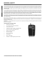
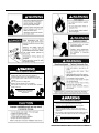
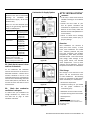
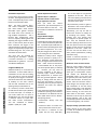
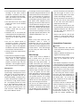
Service Handbook
Residential FVIR
Gas Water Heaters
MODELS:
GCV, GCVH, GVR, GCVL, GVRL, GCVT - SERIES 300/301
XCV, XVR, XCVL, XGV, XVRL, XCVT - SERIES 300/301
LOW LEAD
CONTENT
THIS SERVICE HANDBOOK IS FOR USE BY QUALIFIED SERVICE PROFESSIONALS ONLY.
327726-001
May 2014
TABLE OF CONTENTS
General Safety .................................................................................................................................................... 4
BASICS
Completed Installation (typical) ......................................................................................................................... 6
System Basics ..................................................................................................................................................... 7
Honeywell® Gas Control Valve/Thermostat ............................................................................................................................ 7
Gas Pressures ............................................................................................................................................................ 7
Temperature Settings ................................................................................................................................................ 7
Combustion Chamber with TCO Switch .................................................................................................................................. 8
Lighting the Pilot / Diagnostic Flash Codes......................................................................................................... 9
Lighting the Pilot: ................................................................................................................................................................... 9
If the Status Light Does Not Blink:........................................................................................................................................... 9
If the Pilot Does Not Light: ...................................................................................................................................................... 9
If the Pilot Lights but the Status Light Does Not Blink:............................................................................................................ 9
Diagnostic Flash Codes .......................................................................................................................................................... 10
0 Flashes (LED not lit) ............................................................................................................................................ 10
Status Light On (solid) ........................................................................................................................................... 10
1 Flash ................................................................................................................................................................... 10
2 Flashes ................................................................................................................................................................ 10
4 Flashes ................................................................................................................................................................ 10
5 Flashes ................................................................................................................................................................ 10
7 Flashes ................................................................................................................................................................ 10
8 Flashes ................................................................................................................................................................ 10
System Checks .................................................................................................................................................. 11
Draft Test .............................................................................................................................................................................. 11
Connections Check ................................................................................................................................................................ 11
Gas Pressure Checks.............................................................................................................................................................. 11
Thermopile Check (Open Circuit) .......................................................................................................................................... 12
Thermopile Check (Closed Circuit) ........................................................................................................................................ 12
Common Issues ................................................................................................................................................ 13
No Hot Water ........................................................................................................................................................................ 13
Not Enough Hot Water .......................................................................................................................................................... 13
Lower Seasonal Water Temperatures ....................................................................................................... 13
Faulty Shower Control Valve/Faucet Valve ............................................................................................... 14
Thermostat Set Too Low ........................................................................................................................... 14
An Increase in Hot Water Usage ............................................................................................................... 14
Undersized Water Heater ......................................................................................................................... 14
Reversed Water Connections ................................................................................................................... 14
Leak in the Plumbing System ................................................................................................................. 14
Sediment Buildup in the Tank ................................................................................................................... 14
2 • Residential Standard Gas Water Heater Service Handbook
Tank Leak............................................................................................................................................................................... 15
Leaking Plumbing Connections ............................................................................................................................... 15
Drips from the T&P Relief Valve Discharge Pipe ..................................................................................................... 15
Temperature Too High ........................................................................................................................................................... 16
Low Water Pressure .............................................................................................................................................................. 16
Water Odor ........................................................................................................................................................................... 16
Service Procedures ........................................................................................................................................... 17
Removing the Manifold/Burner Assembly ............................................................................................................................ 17
Removing the Burner from the Manifold/Burner Assembly ................................................................................................. 17
Replacing the Pilot/Thermopile Assembly ............................................................................................................................ 17
External Inspection and Cleaning of the Base-Ring Filter ..................................................................................................... 18
Cleaning the Combustion Chamber and Flame Arrestor....................................................................................................... 18
Replacing the Manifold/Burner Assembly ............................................................................................................................ 19
Testing the Igniter System ..................................................................................................................................................... 19
Removing and Replacing the Gas Control Valve/Thermostat................................................................................................ 20
Removing the Gas Control Valve/Thermostat:........................................................................................................ 20
Replacing the Gas Control Valve/Thermostat: ........................................................................................................ 20
Draining and Flushing............................................................................................................................................................ 20
Supplements..................................................................................................................................................... 21
Evaluating Combustion and Ventilation Air Supply ............................................................................................................... 21
Attic Installations .................................................................................................................................................................. 23
Overview ................................................................................................................................................................. 23
Pilot Outage ............................................................................................................................................................ 23
Elevated Air Temperature: ........................................................................................................................ 24
Insufficient Makeup Air ............................................................................................................................ 24
Blocked Air Screen or Flame Arrestor ....................................................................................................... 24
Improper Venting of the Water Heater .................................................................................................... 24
Decompression ........................................................................................................................................ 25
Wind ........................................................................................................................................................ 25
Water Damage ........................................................................................................................................................ 25
Elevated Water Temperature .................................................................................................................................. 25
Field Installation of Draft Hoods ........................................................................................................................................... 26
Tools and Materials ................................................................................................................................................. 26
Types of Draft Hoods Covered in this Section ......................................................................................................... 26
Types of Vent Pipe Covered in this Section ............................................................................................................. 27
Installation Procedure ............................................................................................................................................. 27
Coupling .................................................................................................................................................................. 27
Type B Draft Hood Connectors................................................................................................................................ 28
Residential Standard Gas Water Heater Service Handbook • 3
BASICS
Condensation .......................................................................................................................................................... 15
BASICS
GENERAL SAFETY
Your safety and the safety of others is extremely important in the servicing of this water heater. Many safety-related messages and
instructions have been provided in this handbook and on your water heater to warn you and others of a potential hazard. Read
and obey all safety messages and instructions throughout this handbook as well as those found in the Installation Instructions/
Use & Care Guide.
It is very important that the meaning of each safety message is understood by you and others who service this water heater.
The information contained in this handbook is designed to answer commonly faced situations encountered in the operation of
the standard Residential Gas product line and is not meant to be all-inclusive. If you are experiencing a problem not covered in
this handbook, please contact the Technical Information Center listed on the back cover of this handbook for further assistance.
Additional information is also available on the web site listed on the back cover of this handbook.
This handbook is intended for use by licensed plumbing professionals and reference should be made to the Installation Instructions
and Use & Care Guide accompanying the product. This handbook contains supplemental information to the Installation Instructions
and Use & Care Guide.
When servicing residential water heaters, it is essential that you return the unit to a safe condition before you leave the site. All
original components must be re-installed and all safety measures must be implemented. In addition, the recommended water
temperature setting is 120° F.
IMPORTANT: It is recommended that on every service call, an inspection & cleaning of the base ring filter and flame arrestor be
performed. See page 18.
Tools Required (for servicing gas models):
•
Phillips head screw driver
•
3/8, 7/16, & 3/4 inch open end wrenches
•
3/16 inch Allen wrench
•
1-1/16 inch – 6 point – socket – for anode removal
•
Electrical multimeter (with alligator leads)
•
Digital or analog manometer
•
Gas pressure gauge
•
Water pressure gauge
•
Thermometer
•
Hose – to drain tank
•
Container – to measure gallons per minute flow
4 • Residential Standard Gas Water Heater Service Handbook
Digital Manometer
BASICS
Fire or Explosion Harzard
Do not store or use gasoline or other flammable vapors and
liquids in the vicinity of this or any other appliance.
Avoid all ignition sources if you smell Natural or LP gas.
Do not expose water heater control to excessive gas
pressure.
Use only gas shown on rating plate.
Maintain required clearances to combustibles.
Keep ignition sources away from faucets after extended
period of non-use.
Read instruction manual before
installing, using or servicing
water heater.
Fire or Explosion Harzard
Hydrogen gas can be produced in a hot water system after
a period of non-use (generally two or more weeks).
Hydrogen gas is extremely flammable and can ignite.
To return hot water system to service, open a hot water
faucet in kitchen for several minutes before using electrical
appliances.
Do not smoke or have open flame near faucet while it is open.
Leave hot water faucet open until the sound of escaping
air stops.
After extended period of non-use,
purge gases from hot water system.
Residential Standard Gas Water Heater Service Handbook • 5
BASICS
COMPLETED INSTALLATION ΈTYPICALΉ
See Labels and
Installation Instructions
and Use & Care Guide
for clearances.
Exhaust Vent to
Ouside of Building
Union
Union
Untempered
Hot Water
Cold
Water
Inlet
Water
Shut-Off
Valve
*Massachusett: Install
a vacuum relief in cold
water line per section
19 MGL 142.
Expansion Tank
Pressurized to Equal
Supply Water Pressure*
(Relieve water pressure
on the expansion tank
before adjusting air
pressure.)
To Fixtures - Hot
Tempered Water
To Fixtures
Water
Supply- Cold*
Gas Supply
Temperature-Pressure Relief Valve
with discharge piped to an
adequate drain. Do not cap or plug.
Manual Gas
Shut-off Valve
Hot
Water
Outlet
Gas Control Valve/Thermostat
Recommended setting of 120°F.
Mixing Valve
(Set to 120°F)
Do not cap or plug.
Follow the Mixing
Valve Manufacturer’s
Instructions
6” Maximum Air Gap
NOTE: Local codes
may vary.
Union
Sediment Trap
3” Minimum.
Base Ring Filter:
Air is drawn in for combustion. Keep area clean
and free from flammables and flammable vapors.
Drain
Metal Drain Pan piped to an adequate drain.
NOTE: Drain pan diameter must be at least
2 inches wider than the diameter of the
water heater.
The water heater must be installed according to all local and state codes or in the absence of local
and state codes, the “National Fuel Gas Code” ANSI Z223.1(NFPA 54)- current edition.
* NOTE: If on a well system, the expansion tank should be set to the maximum pressure of the pump tank.
Figure 1.
6 • Residential Standard Gas Water Heater Service Handbook
Honeywell® Gas Control
Valve/Thermostat
error codes, see “Lighting the Pilot /
Diagnostic Flash Codes” on page 9.
Water heaters covered by this handbook
are equipped with Honeywell gas
control valve/thermostats.
WŝůŽƚŇĂŵĞŚĞĂƚƐƚŚĞƌŵŽƉŝůĞ͕
ĞŶĂďůŝŶŐŐĂƐĐŽŶƚƌŽůǀĂůǀĞͬ
ƚŚĞƌŵŽƐƚĂƚŽƉĞƌĂƟŽŶ͘
Pilot
• The Honeywell valve uses a
thermopile instead of a thermocouple
as did previous designs.
T
r
he
m
op
ile
• Heat on the thermopile generates
750 to 900 millivolts (open circuit).
• When heated by the pilot and
connected to the Honeywell control,
the thermopile generates at least
350 millivolts (closed circuit). This
voltage opens the power head
in the control, allowing gas to
flow. It also powers the onboard
diagnostics (status light).
See
Figure 2.
• The Honeywell valve uses a standard
push-button piezo igniter. See “Spark
Igniter” in Figure 2B.
• Status codes are printed on the face
of the control for easy reference
(Figure 2B.)
• The LED status light shows the
current status of the control as well
as possible error codes for easy
diagnosis. For more information on
The gas control valve\thermostat also
includes a temperature limiting ECO
(Energy Cut Off) system. This system
will shut off the water heater if the
water temperature becomes excessive.
Should the water temperature get
too high, the main burner and pilot
will shut off automatically. Once the
pilot is relit, the status light will flash
a code (4 flashes), indicating an overtemperature condition. See “Lighting
the Pilot / Diagnostic Flash Codes” on
page 9 for more information.
NOTE: Honeywell is a registered trademark
of Honeywell International, Inc.
Temperature Seƫngs
Figure 2.
Gas Pressures
Ensure that the following pressures are
observed and maintained:
Table 1. GAS PRESSURES
GAS
MAXIMUM
SUPPLY
PRESSURE
MANIFOLD
GAS
PRESSURE
NAT
14 InWC
5.0 InWC
(± 0.4 InWC)
LP
14 InWC
10.0 InWC
(± 0.5 InWC)
The water temperature setting can be
adjusted from 55°F to 155°F. Simply
turn the gas control/temperature Knob
to the desired setting/temperature.
See Figure 3.
NOTE: The temperatures indicated are
approximates. The actual temperature
of the heated water may vary.
Min. Supply Pressure: See Rating Plate.
Figure 2B
Temperature Control Knob*
Temperature control ranges:
ͻϱϱΣ&ͲϭϱϱΣ&ǁŝƚŚsƐĞƫŶŐ
ͻϵϭΣ&ͲϭϱϱΣ&ǁŝƚŚŽƵƚsƐĞƫŶŐ
* Some models do not
ŝŶĐůƵĚĞĂs;ǀĂĐĂƟŽŶͿƐĞƫŶŐ͘
Residential Standard Gas Water Heater Service Handbook • 7
BASICS
SYSTEM BASICS
BASICS
Scalding Risk
A
water
heater
can make water
hot
enough
to
cause severe burns
instantly, resulting in severe injury or
death. Higher temperatures increase
the risk of scalding, but even at 120°F,
hot water can scald. See Table 2.
Thermostatic mixing valves at each
point of use reduce the risk of scalding.
HONEYWELL® GAS CONTROL VALVE/THERMOSTAT
GAS CONTROL/TEMPERATURE KNOB
§150°F
§140°F
§155°F
§130°F
120°F
MARK
VAC
STATUS
LIGHT
§55°F
IGNITER
TEMPERATURES SHOWN ARE APPROXIMATES AND MAY VARY.
SOME MODELS ARE CERTIFIED FOR 180°F. SEE RATING PLATE.
Figure 3.
Table 2.
Water
Time to Produce
Temperature a Serious Burn
120°F (49°C)
More than 5 minutes
125°F (52°C)
1½ to 2 minutes
130°F (54°C)
About 30 seconds
135°F (57°C)
About 10 seconds
140°F (60°C)
Less than 5 seconds
145°F (63°C)
Less than 3 seconds
150°F (66°C)
About 1½ seconds
155°F (68°C)
About 1 second
IMPORTANT: Water temperature
in the tank can be higher than the
thermostat setting. Some of the
reasons are:
• Incoming water temperature is
higher than the set point (e.g.,
solar-heated water).
• The water heater and/or pipes
are located in an area with high
ambient temperatures (e.g., an
attic). See also “Attic Installations”
on page 23.
• Certain usage patterns, such as
short hot water draws or no hot
water use for long periods of
time, can cause the tank water
temperature to rise higher than the
thermostat setting. Modern water
heaters are very well insulated
and retain heat so efficiently that,
under certain circumstances,
the tank water temperature can
increase over time, particularly
when hot water is not being used.
This “heating” effect can be caused
by the pilot flame itself.
is located in the center of the switch,
directly between the terminals.
IMPORTANT: If the thermal switch has
been tripped, determine the cause
and correct it before returning the
water heater to service. Ensure that
there are no flammable vapors
present. However, a tripped thermal
switch is most likely caused by poor
combustion (e.g., blocked vent or dirty
filter/arrestor).
THERMAL SWITCH (TCO) LOCATION
CombusƟon Chamber
with TCO Switch
Combustion air is drawn through the
base-ring filter and flame arrestor and
into the combustion chamber. (See
Figure 5.) Sufficient combustion air is
critical to the operation of the water
heater.
THERMAL
SWITCH
(TCO)
IMPORTANT: The flame arrestor
and filter should be inspected and
cleaned during each service call. See
page 18 for instructions.
Also, each water heater covered by
this handbook is equipped with a
resettable TCO switch (thermal switch),
designed to shut off the gas supply in
the event that the water heater has
been exposed to high combustion
chamber temperatures caused by one
of the following events:
• Flammable vapors (e.g., spilled
gasoline)
• Poor combustion caused by a
blocked vent
• Insufficient combustion air.
A resettable thermal switch is
illustrated in Figure 4. Its reset button
8 • Residential Standard Gas Water Heater Service Handbook
Figure 4.
FLAME ARRESTOR
COMBUSTION CHAMBER
BASE-RING
FILTER
Figure 5.
LIGHTING THE PILOT / DIAGNOSTIC FLASH CODES
1. Read and follow the lighting
instructions on the water heater’s
label.
2. Turn the control knob to “Pilot.”
Press the knob in fully and hold it in.
(The knob will travel in about 1/4inch if it is set to Pilot correctly.)
3. While holding the control knob in,
click the igniter button continuously
for up to 90 seconds or until the
Status Light begins to blink.
If the status light does not begin
to blink after 90 seconds, STOP.
Release the control knob. Wait
10 minutes before attempting to
relight the Pilot. Repeat these steps
2-3 times, if necessary.
The circuitry in this gas valve
requires that you wait 10 minutes
between lighting attempts.
If the Status Light blinks, release
the gas control/temperature knob
and turn it to the desired setting.
(“Hot” is approximately 120°F).
'ĂƐŽŶƚƌŽůͬdĞŵƉĞƌĂƚƵƌĞ<ŶŽď
/ŐŶŝƚĞƌƵƩŽŶ
Figure 6.
If the Status Light Does
Not Blink:
1. Wait 10 minutes before another
lighting attempt.
2. If the status light did not blink, repeat
the lighting procedure by following
the lighting instructions on the water
heater’s label. Remove the outer
door. The control knob must be set
to Pilot and held in continuously
while clicking the igniter button
(about once per second for up to
90 seconds). To observe the Pilot,
remove the outer door and look
through the view port (sight glass).
See Figure 7.
3. Continue clicking the Igniter button
(for up to 90 seconds) until pilot
lights.
4. Once the pilot is lit, continue to hold
the control knob in until the Status
Light begins to blink.
5. Release control Knob and set Knob to
desired temperature setting. (“Hot”
is approximately 120°F.)
6. Replace the outer door.
If the Pilot Does Not
Light:
1. Wait 10 minutes before another
lighting attempt. If the pilot does not
light, the Igniter may not be sparking
or the unit may not be getting gas (or
for a new installation, there may still
be air in the gas line). Each time you
click the igniter button, you should
be able to see the spark by looking
through the view port. See Figure 7.
(You may have to darken the room
lights to see the spark.) You do not
have to push the Control Knob in
to check the Igniter button. Simply
look through the sight glass while
clicking the Igniter button and look
for a spark. If you can’t see a spark
when the Igniter button is clicked,
check the wiring connections from
the Igniter button and make sure
that they are tight.
2. If you see the igniter spark, try
relighting the pilot by following the
instructions on the water heater’s
label. Ensure that the gas supply is
turned on. There may be air in the
gas line, and several lighting attempts
may be needed to completely fill the
line with gas and successfully light
the pilot.
'^KEdZK>V>sͬd,ZDK^TAT
'^KEdZK>ͬ
dDWZdhZ<EK
d,ZDKW/>
t/ZKEEd/KE^
VAC
W/K/'E/dZhddKE
V/tWKZd
THERMAL
SWITCH
ΈdKΉ
KhdZKKZ
EKd^,KtE
Figure 7.
If the Pilot Lights but the
Status Light Does Not
Blink:
1. If the pilot lights, continue to hold the
control knob in until the status light
blinks. If the pilot is lit and remains
lit for 90 seconds and the Status Light
still does not blink, the thermopile
connections may be loose, the
thermal switch may need to be reset,
or the thermopile may be defective.
2. Remove the outer door.
3. Press the reset button on the thermal
switch (TCO switch). See Figure 7.
4. If the switch clicks, it may have
tripped. Do not light the pilot if
flammable vapors are present.
Check flame arrestor for signs
of discoloration (which could be
caused by flammable vapors). If the
flame arrestor is discolored, do not
attempt to relight the Pilot. Have the
water heater inspected by a qualified
service technician.
5. Check the wiring connections
from the thermopile and thermal
switch (TCO) to the gas control
valve/thermostat.
Ensure that
all wiring connections are tight.
See Figure 7.
6. Replace the outer door.
Residential Standard Gas Water Heater Service Handbook • 9
PILOT/FLASH CODES
LighƟng the Pilot:
PILOT/FLASH CODES
7. Wait 10 minutes and try to light the
Pilot according to the instructions
on the water heater’s label.
8. While clicking the igniter button
continuously, the control knob must
be set to Pilot and held in until the
Status Light blinks. Once the status
light blinks, release the control knob
and set the knob to the desired
temperature setting.
(“Hot” is
approximately 120°F.)
DiagnosƟc Flash Codes
NOTE: In each case, the flash code will
occur, followed by a 3 second pause,
and then will repeat.
0 Flashes (LED not lit)
Indication/Condition:
Control Off/Pilot Out.
Check/Repair:
1. Follow the lighting instructions on the
front of the water heater and attempt
to relight the pilot. Confirm that
the pilot is lit by looking through the
viewport (Figure 16, p. 17).
2. If pilot will light but does not
hold, check for a tripped thermal
switch. (Measure continuity by
placing a meter lead on each of
the two terminals. Continuity
means that it was not tripped.) If
thermal switch is tripped, check for
flammable vapors in the area and
ensure that the unit has adequate
combustion air and proper draft
before relighting. (You can reset
the thermal switch by pressing the
reset button in its center.) Also,
ensure that the filter and flame
arrestor are clean (p. 18).
the Igniter System” (p. 19);
“Gas Pressure Checks” (p. 11).
Also, check the thermopile wiring
connections (Figure 16, p. 17).
4 Flashes
Indication/Condition:
Temperature exceeded (ECO activated).
Check/Repair:
Status Light On (solid)
Indication/Condition:
Pilot light was recently extinguished
and the thermopile is cooling down.
Check/Repair:
1. Turn the gas control
thermostat knob to OFF.
valve/
2. Wait 10 minutes for the thermopile
to cool, then attempt to relight
the pilot by following the lighting
instructions on the water heater’s
label. NOTE: This gas control valve/
thermostat has built-in circuitry
that requires waiting 10 minutes
between lighting attempts.
Until the Thermopile reaches its
normal operating temperature,
the status light will not blink, even
if the pilot is lit. It may take up to
90 seconds of continuous pilot
operation before the thermopile
reaches
normal
operating
temperature and the Status Light
starts to blink.
1. Turn gas control valve/thermostat
knob to OFF.
2. Turn the main gas supply OFF.
3. Replace the gas control valve/
thermostat.
5 Flashes
Indication/Condition: Sensor failure.
Check/Repair:
1. Turn gas control valve/thermostat
knob to OFF.
2. Turn the main gas supply OFF.
3. Replace the gas control valve/
thermostat.
7 Flashes
Indication/Condition:
Internal control failure.
Check/Repair:
1. Turn gas control valve/thermostat
knob to OFF.
2. Turn the main gas supply OFF.
1 Flash
Indication/Condition:
Normal
Operation
heartbeat)
Check/Repair:
necessary.
3. Replace the gas control valve/
thermostat.
(bright/dim
No corrective action
2 Flashes
Indication/Condition:
Thermopile voltage low.
3. If the pilot will light and does hold,
record any status codes and follow
the procedures relating to that code.
Check/Repair:
4. If pilot will not light at all, verify the
piezo igniter is producing a spark
and the unit is getting the correct
supply gas pressure. See “Testing
2. Check the millivolt output on the
thermopile. If output is less than 350
millivolts DC, replace the thermopile.
1. Check all wiring connections for loose
or damaged wires. Correct if needed.
See also “Condensation” on page 15.
10 • Residential Standard Gas Water Heater Service Handbook
8 Flashes
Indication/Condition: Power off failure.
Check/Repair:
1. If the pilot flame is present when
the control knob is set to the OFF
position, replace the gas control
valve/thermostat.
2. If the pilot flame is not present when
the control knob is set to the OFF
position, wait 10 minutes for the
thermopile to cool, then relight the
unit. If this condition returns, replace
the gas control valve/thermostat.
SYSTEM CHECKS
Explosion Risk
WARNING! Before performing any
test, check the area around the water
heater for any source of a flammable
vapor (i.e gasoline, paint thinners,
etc.). If any sources are found, do not
proceed until they are removed.
DraŌ Test
WARNING! Burn Hazard. Do not
touch the vent. Doing so can cause
burns.
After successfully lighting the water
heater, allow the main burner to
operate for five minutes. Close all
windows and doors and turn on all
gas appliances and air-moving devices
(range hoods, bathroom exhaust fans,
ceiling fans, etc.) in the home. Also,
close any fireplace dampers.
Some issues can be caused by faulty
connections. Refer to the following list
of connections when troubleshooting
the system:
• Igniter wire (Figure 9). See also
“Testing the Igniter Sy