1
On-Demand Water Heater
Installation Manual and Owner’s Guide
ANSIZ21.10.3andCSA4.3
Models
510U(T-D2U)
modelsonly
• 110U Indoor (T-KJr2U-IN) • 110U Outdoor (T-KJr2U-OS)
• 310U Indoor (T-K4U-IN) • 310U Outdoor (T-K4U-OS)
• 510U Indoor (T-D2U-IN) • 510U Outdoor (T-D2U-OS)
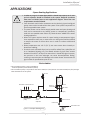
If the information in these
instructions is not followed
exactly,afireorexplosionmay
resultcausingpropertydamage,
WARNING personalinjuryordeath.
- Do not store or use gasoline or other
flammablevaporsandliquidsinthevicinity
ofthisoranyotherappliance.
- WHATTODOIFYOUSMELLGAS
• Donottrytolightanyappliance.
• Donottouchanyelectricswitch,donot
useanyphoneinyourbuilding.
• Immediatelycallyourgassupplierfrom
aneighbor'sphone.Followthegas
supplier'sinstructions.
Gas Tankless Water HeaterTM
• Ifyoucannotreachyourgassupplier,call
Suitable for potable water heating and space-heating*
thefiredepartment.
* Please refer to local codes for space-heating compliance.
- Installation and service must be performed
byaqualifiedinstaller,serviceagencyorthe
gassupplier.
FEATURING
• ENDLESSHOTWATER
• ON-DEMANDUSAGE
• COMPACT,SPACESAVING
• ENERGYCONSERVATION
• COMPUTERIZEDSAFETY
• NOPILOTLIGHT
• Satisfiesthe2012SCAQMDRule
1146.2forUltra-LowNOx
Emissions
• EASY-LINKSYSTEMAND
MULTI-UNITSYSTEM
(510U (T-D2U) models only)
Ifyouhaveanyquestions,please
callorwriteto:
500TennesseeWaltzParkway
AshlandCity,TN37015
TollFree:1-877-737-2840
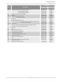
CONTENTS
Installation Manual
SPECIFICATIONS.......................................................................................................................... 4
INTRODUCTION.......................................................................................................................... 5
SAFETYGUIDELINES.................................................................................................................... 6
INSTALLATION............................................................................................................................. 7
General.....................................................................................................................................7
Clearances................................................................................................................................9
IncludedAccessories...............................................................................................................9
OptionalItems........................................................................................................................9
WarningforInstallations..........................................................................................................9
High-altitudeInstallations......................................................................................................12
VentingInstructions...............................................................................................................13
Gassupplyandgaspipesizing...............................................................................................18
WaterConnections................................................................................................................20
ElectricalConnections............................................................................................................21
TemperatureRemoteController...........................................................................................22
Easy-linkSystem.....................................................................................................................25
Multi-UnitSystem..................................................................................................................29
APPLICATIONS............................................................................................................................30
INITIALOPERATION...................................................................................................................32
Owner's Guide
OPERATINGSAFETY.................................................................................................................. 34
NORMALOPERATION............................................................................................................... 36
General..................................................................................................................................36
TemperatureSettings.............................................................................................................37
Flow.......................................................................................................................................40
Freezeprotectionsystem.......................................................................................................40
Maintenanceandservice.......................................................................................................41
UnitDrainingFilterCleaning..................................................................................................41
TROUBLESHOOTING...................................................................................................................42
General...................................................................................................................................42
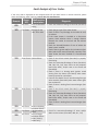
ErrorCodes...........................................................................................................................44
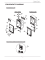
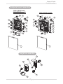
COMPONENTSDIAGRAM...........................................................................................................47
PARTSLIST.................................................................................................................................51
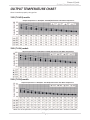
OUTPUTTEMPERATURECHART................................................................................................54
LIMITEDWARRANTY..................................................................................................................55
2
Page
Installation Manual
Contents
Installation Manual
CONGRATULATIONS
Congratulationsandthankyouforchoosingourtanklesswaterheater.
Beforeuse,werecommendthatyoureadthroughthissafetymanual
carefully.Pleaserefertothebackofthemanualfordetailsaboutthe
warranty.Keepthismanualforfuturereference.
If you lose the manual, contact the manufacturer or your local
distributor. When you call, please tell us the product name and the
serial number of your unit written on the rating plate of the water
heater.
3
Page
Installation Manual
Specifications
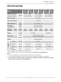
SPECIFICATIONS
110U
Indoor
Model
110U
Outdoor
310U
Indoor
310U
Outdoor
BTU/h
Min.:15,000
Max.:140,000
Min.:15,000
Max.:190,000
Gas Connection
3/4"NPT
Water Connections
3/4"NPT
Water Pressure*
Natural gas
Inlet Pressure
Manifold
Pressure**
Natural
Gas
Weight
psi
(Mpa)
"W.C.
(kPa)
"W.C.
(Pa)
Min.:15,000
Max.:199,000
15-150(0.1-1)
1.8
(448)
1.5
(373)
lbs.(kg)
Dimensions
Min.5.0(1.24)
Max.10.5(2.61)
3.0
2.9
(747)
(722)
37(16.9)
inch
mm
3.3
(821)
2.9
(722)
39(17.9)
H20.5xW13.8xD8.5
H520xW351xD216
Ignition
Consumption
510U
Outdoor
(T-KJr2U-IN) (T-KJr2U-OS) (T-K4U-IN) (T-K4U-OS) (T-D2U-IN) (T-D2U-OS)
Natural Gas Input
(OperatingRange)
Electric
510U
Indoor
ElectricIgnition
Supply
VAC/Hz
120/60
Operation
W/A
52.1/0.54
75.8/0.83
81.6/0.86
Standby
W/A
5.4/0.08
5.5/0.08
6.5/0.09
FreezeW/A
131/1.1
131/1.1
132/1.1
Protection
*40psioraboveisrecommendedformaximumflow.
**TheManifoldPressureisthefactorysettingandgenerallyshould not need adjustment.
NOTE:
• Checktheratingplatetoensurethisproductmatchesyourspecifications.
• InaccordancewithANSIZ21.10.3,COemissiondoesnotexceed400PPMfornormalinput.
• The manufacturer reserves the right to discontinue, or change at any time, specifications or designs
without notice and without incurring obligations.
4
Page
Installation Manual
Introduction
INTRODUCTION
• Thismanualprovidesinformationnecessaryfortheinstallation,operation,andmaintenance
ofthewaterheater.
• Themodeldescriptionislistedontheratingplatewhichisattachedtothefrontpanelofthe
waterheater.
• Pleasereadallinstallationinstructionscompletelybeforeinstallingthisproduct.
• Ifyouhaveanyproblemsorquestionsregardingthisequipment,consultwiththemanufacturer
oritslocalrepresentative.
• Thisequipmentisanon-demand,tanklesswaterheaterdesignedtoefficientlysupplyendless
hotwaterforyourneeds.
• The 110U Indoor (T-KJr2U-IN), 310U Indoor (T-K4U-IN) and 510U Indoor (T-D2U-IN) models
are to be installed indoor (direct-vent convertible). The 110U Outdoor (T-KJr2U-OS), 310U
Outdoor(T-K4U-OS)and510UOutdoor(T-D2U-OS)modelsaretobeonlyinstalledoutdoor.
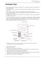
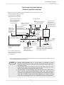
• Theprinciplebehindtanklesswaterheatersissimple:
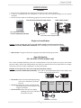
Exhaustventcollar
Burners
Heatexchanger
Burners
Flowadjustmentvalve
Computerboard
Gasvalves
Flowsensor
Thermistor
Fanmotor
Thermistor
Hotwateroutlet
Gasinlet
Coldwaterinlet
*Thisdiagramillustratestanklesswaterheaterdesignconceptsonlyanddoesnotaccurately
representthewaterheater’sphysicaldescription.
1.
2.
3.
4.
5.
6.
7.
Ahotwatertapisturnedon.
Waterenterstheheater.
Thewaterflowsensordetectsthewaterflow.
Thecomputerinitiatesthefanmotorandsendsasignaltotheignitertocreateanignitionspark.
Thegasignitesandflamesappearwithintheburnerchamber.
Watercirculatesthroughtheheatexchangerandthengetshot.
Usingthermistorstomeasuretemperaturesthroughoutthewaterheater,thecomputermodulates
thegasandwatervalvestoensureproperoutputwatertemperature.
8. Whenthetapisturnedoff,theunitshutsdown.
5
Page
Installation Manual
Safety Guidelines
SAFETY GUIDELINES
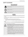
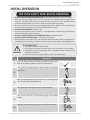
SAFETY DEFINITION
DANGER
WARNING
CAUTION
Indicatesanimminentlyhazardoussituationwhich,ifnotavoided,willresultin
deathorseriousinjury.
Indicatesanimminentlyhazardoussituationwhich,ifnotavoided,couldresult
indeathorseriousinjury.
Indicatesanimminentlyhazardoussituationwhich,ifnotavoided,couldresult
inminorormoderateinjury.
GENERAL
1. Followalllocalcodes,orintheabsenceoflocalcodes,followthemostrecenteditionoftheNational
FuelGasCode:ANSIZ223.1/NFPA54intheUSAorCAN/CSAB149.1NaturalGasInstallationCode
inCanada.
2. Properlygroundtheunitinaccordancewithalllocalcodesorintheabsenceoflocalcodes,withthe
NationalElectricalCodes:ANSI/NFPA70intheUSAorCSAstandardC22.1CanadaElectricalCode
Part1inCanada.
3. Carefullyplanwhereyouintendtoinstallthewaterheater.Pleaseensure:
•Yourwaterheaterwillhaveenoughcombustibleairandproperventilation.
•Locateyourheaterwherewaterleakagewillnotdamagesurroundingareas(pleasereferto
p.8).
4. ChecktheratingplateforthecorrectGAS TYPE, GAS PRESSURE, WATER PRESSURE and ELECTRIC
RATING.
*Ifthisunitdoesnotmatchyourrequirements,do not install and consult with the manufacturer.
5. Ifanyproblemshouldoccur,turnoffallhotwatertapsandturnoffthegas.Thencallatrained
technicianortheGasCompanyorthemanufacturer.
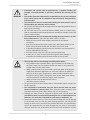
• Watertemperaturesover125°F(52°C)cancausesevereburnsinstantlyor
deathfromscalding.Thewatertemperatureissetat120°F(49°C)fromthe
factory to minimize any scalding risk. Before bathing or showering always
checkthewatertemperature.
WARNING
• Do not store or use gasoline or other flammables, vapors, or liquids in the
vicinityofthisappliance.
• Donotreversethewaterand/orgasconnectionsasthiswilldamagethegas
valvesandcancausesevereinjuryordeath.Followthediagramonp.20when
installingyourwaterheater.
• Do not use this appliance if any part has been in contact with or been
immersedinwater.Immediatelycallalicensedplumber,alicensedgasfitter,
or a professional service technician to inspect and/or service the unit if
necessary.
• Do not disconnect the electrical supply if the ambient temperature will
drop below freezing. The Freeze Prevention System only works if the unit
haselectricalpower.Thewarrantywillnotbecoverediftheheatexchanger
is damaged due to freezing. Refer to the section on the Freeze Prevention
Systemonp.39formoreinformation.
6
Page
Installation Manual
Installation
INSTALLATION
GENERAL
1. Followalllocalcodes,orintheabsenceoflocalcodes,followthemostrecenteditionoftheNational
FuelGasCode:ANSIZ223.1/NFPA54intheUSAorCAN/CSAB149.1NaturalGasInstallationCodein
Canada.
2. Allgaswaterheatersrequirecarefulandcorrectinstallationtoensuresafeandefficientoperation.This
manualmustbefollowedexactly.Readthe“SafetyGuidelines”section.
3. The manifold gas pressure is preset at the factory. It is computer controlled and should not need
adjustment.
4. Maintain proper space for servicing. Install the unit so that it can be connected or removed easily.
Refertothe"Clearances"sectiononp.9forproperclearances.
5. Thewaterheatermustbeinstalledinalocationwheretheproperamountofcombustibleairwillbe
availabletoitatalltimeswithoutobstructions.
6. Theelectricalconnectionrequiresameansofdisconnection,toterminatepowertothewaterheater
forservicingandsafetypurposes.
7. Donotinstalltheunitwheretheexhaustventispointingintoanyopeninginabuildingorwherethe
noise may disturb your neighbors. Make sure the vent termination meets the required distance by
localcodefromanydoorwayoropeningtopreventexhaustfromenteringabuilding(refertop.14).
8. Particlesfromflour,aerosols,andothercontaminantsmayclogtheairventorreducethefunctions
oftherotatingfanandcauseimproperburningofthegas.Regularlyensurethattheareaaroundthe
unitisdust-ordebris-free;regularmaintenanceisrecommendedforthesetypesofenvironment.
9. Ifyouwillbeinstallingthewaterheaterinacontaminatedareawithahighlevelofdust,sand,flour,
aerosolsorothercontaminants/chemicals,theycanbecomeairborneandenterandbuildupwithin
thefanandburnercausingdamagetothewaterheater.
10.Forthe110UIndoor(T-KJr2U-IN),310UIndoor(T-K4U-IN)and510UIndoor(T-D2U-IN)models:
•Theseunitsmaybeconvertedtoadirect-vent(sealedcombustion)appliancebyinstalling
adirect-ventconversionkitPartNo.9007667005(TK-TV10)whichwillbringinallrequired
combustibleairfromoutsidethebuilding.Wheninstallingthedirect-ventconversionkit,please
followallinstructionsincludedwiththekit.
•Ifthewaterheaterisusedasadirect-ventappliance,theunitrequiresa3in.(76mm)
combustibleairsupplypipe.Theintakepipemustbesealedairtight.Airsupplypipecanbe
madeofABS,PVC,galvanizedsteel,corrugatedaluminum,corrugatedstainlesssteelorCategory
IIIstainlesssteel.
•Terminatingtheventingthroughasidewallisrecommendedforthedirect-ventsystem.
•Runningtheexhaustventandtheintakepipeparallelisrecommended.
•Terminatingtheexhaustandintakeonthesamewall/surfaceisrecommended.Terminatingin
thesamepressurezoneallowsforpressurebalancing,whichpreventsnuisanceshutdowns.
11.Forthe110UOutdoor(T-KJr2U-OS),310UOutdoor(T-K4U-OS)and510UOutdoor(T-D2U-OS)models:
•Tobeinstalledoutdoorsandonlyinareaswithmild,temperateclimates.
7
Page
Installation Manual
Installation
• Installation and service must be performed by a qualified installer (for
example, a licensed plumber or gas fitter), otherwise the warranty will be
void.
WARNING • The installer (licensed professional) is responsible for the correct installation
of the water heater and for compliance with all national, state/provincial,
and local codes.
• The manufacturer does not recommend installing the water heater in a pit or
location where gas and water can accumulate.
• Donothavetheventterminalpointingtowardanyoperatingwindow,door,or
openingintoabuilding.
• Do not install next to any source of airborne debris, such as a clothes dryer,
thatcancausedebristobetrappedinsidethecombustionchamber,unlessthe
systemisdirect-vented.
• The manufacturer does not recommend installing the water heater in an attic
due to safety issues.Ifyouinstallthewaterheaterinanattic:
• Makesuretheunitwillhaveenoughcombustionairandproper
ventilation.
• Keeptheareaaroundthewaterheaterclean.Whendustcollectsonthe
flamesensor,thewaterheaterwillshutdownonanerrorcode.
• Iftheaboveconditionscannotbemet,usethedirectventconversionkit
PartNo.9007667005(TK-TV10).
• Placetheunitforeasyaccessforserviceandmaintenance.
• Adrainpan,orothermeansofprotectionagainstwaterdamage,is
requiredtobeinstalledunderthewaterheaterincaseofleaks.
INCLUDED ACCESSORIES
CAUTION
• The warranty will not cover damage caused by water quality.
• Onlypotablewaterorpotablewater/glycolmixturescanbeusedwith
thiswaterheater.Donotintroducepoolorspawater,oranychemically
treatedwaterintothewaterheater.
• Waterhardnesslevelsmustnotexceed7grainspergallon(120ppm)for
singlefamilydomesticapplicationsormorethan4grainspergallon(70
ppm)forallothertypesofapplications.Waterhardnessleadstoscale
formationandmayaffect/damagethewaterheater.Hardwaterscaling
mustbeavoidedorcontrolledbyproperwatertreatment.
• WaterpHlevelsmustbebetween6.5and8.5
• Wellwatermustbetreated.
• Donotinstalltheunitwherewater,debris,orflammablevaporsmaygetinto
theflueterminal.
• The manufacturer recommends using the direct vent kit when the water
heater is installed in a beauty salon.Somechemicalsusedinabeautysalon
mayaffecttheflamesensor.Waterheatermaynotworkproperly.
• Although the water heater is designed to operate with minimal sound, the
manufacturer does not recommend installing the unit on a wall adjacent to a
bedroom, or a room that is intended for quiet study or meditation, etc.
• Locateyourheaterclosetoadrainwherewaterleakagewillnotdodamage
to surrounding areas. As with any water heating appliance, the potential for
leakageatsometimeinthelifeoftheproductdoesexist.Themanufacturer
willnotberesponsibleforanywaterdamagethatmayoccur.Ifyouinstalla
drainpanundertheunit,ensurethatitwillnotrestrictthecombustionairflow.
OPTIONAL ITEMS
8
Page
Installation Manual
Installation
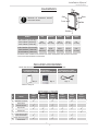
CLEARANCES
Top
Black
Side
Maintain all clearances around
thewaterheater.
Front
Side
Bottom
Model
Top
Bottom
Front
Back
Sides
110UIndoor(T-KJr2U-IN)*
310UIndoor(T-K4U-IN)*
510UIndoor(T-D2U-IN)*
12in.
(305mm)
12in.
(305mm)
4in.**
(102mm)
0.5in.
(13mm)
2in.
(51mm)
110UOutdoor(T-KJr2U-OS)
36in.
310UOutdoor(T-K4U-OS) (914mm)
510UOutdoor(T-D2U-OS)
12in.
(305mm)
24in.
(610mm)
0.5in.
(13mm)
2in.
(51mm)
*Standardindoorinstallationsanddirect-ventindoorinstallationshavethesameclearances.
**24inchrecommendedformaintenance.
INCLUDED ACCESSORIES
Checkthattheseitemsbelowareincludedwiththewaterheater.
Installation Manual Temperature
Communication Cable
and Owner’s Guide Remote Controller Kit* 510U (T-D2U) models only
Qty:1
Qty:1
Qty:1
*Refertothep.22.
OPTIONAL ITEMS
#
Model
1.
BackflowPreventer
Direct-Vent
ConversionKit
Pipecovers
2.
3.
110U
110U
Indoor
Outdoor
(T-KJr2U-IN) (T-KJr2U-OS)
✓
✓
✓
4.
Recessbox
T-VentWallThimble
5.
withTermination
Direct-VentConcentric
6.
Termination
✓
✓
✓
✓
310U
Indoor
(T-K4U-IN)
✓
✓
✓
✓
✓
9
Page
310U
Outdoor
(T-K4U-OS)
✓
✓
510U
Indoor
(T-D2U-IN)
✓
✓
✓
✓
✓
510U
Outdoor
(T-D2U-OS)
✓
✓
Installation Manual
Installation
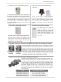
1. Backflow Preventer: 9007678005 (TK-BF01)
TheBackflowpreventerpreventsthebackflowof
air through the exhaust vent. This helps prevent
harmfulexhaustgasesfromenteringthehome,as
wellashelpingtopreventtheunitfromfreezingin
areaswherecoldaircanbeblownordrawninto
the exhaust system. Install this vent damper in
accordance with the installation instructions and
anyapplicablecodes.
3. Pipe covers: 9007670005 (TK-PC01)
2. Direct-Vent Conversion Kit: 9007667005
(TK-TV10)
This kit can be used to convert the water
heaterfromastandardventsystemtoadirectvent (or sealed combustion) system. Install
this conversion kit in accordance with the
installation instructions and any applicable
codes.
4. Recess box: 9007674005 (TK-RB02)
The Recess box will allow for
“clean” installations. The water
heater fits inside the recess box,
whichhidesandprotectsthewhole
water heater and plumbing. The
Recessboxwillfitin-betweenmost
wallstuds.
Thepipe coverprotectstheplumbing pipes to
thewaterheaterfromunexpectedadjustments.
This pipe cover is fixed to the bottom of the
water heater, which hides the plumbing and
improves the visual aspects of the whole
installationforthewaterheater.
5. T-Vent Wall Thimble with Termination: 9007608005 (TK-KPWL4) and 9007609005 (TK-KPWH4)
Theseterminationsareusedwhenventingoutthroughthewalland
arecompatiblewiththeT-Ventpipesystem.Theseterminationsare
special stainless steel vents for gas appliances and are UL listed as
CategoryII,IIIandIV.Therearetwotypesofterminations:theLouver
terminationandtheHoodtermination.Fordifferentwallthicknesses,
Louver Termination Hood Termination therearetworangesoflengthsavailable(refertotheT-Ventbrochure
9007609005
9007608005
fordetails).Installtheseventterminationsinaccordancewiththeir
(TK-KPWL4)
(TK-KPWH4)
installationinstructionsandanyapplicablelocalcodes.
6. Direct-Vent Concentric Termination: 900768005 (TK-KPCT43)
Usedwhenterminatingdirect-vent(sealed-combustion)systems,with
direct-ventmodelsthatrequirea3in.(76mm)intakeanda4in.(102
mm) exhaust. This concentric termination provides the convenience
of only having to make one penetration through a sidewall instead
of two separate penetrations for the intake and exhaust piping. The
termination includes a bird screen, restricting small animals, pests,
andforeignobjectsfromenteringintotheventsystem.Thissidewall
terminationisavailableinthreedifferentsizes,tocoverallrangesof
wallthicknesses.
Part#
9007680005(TK-KPCT43-1)
9007772005(TK-KPCT43-2)
9007773005(TK-KPCT43-3)
10
Convering wall thicknesss
3.9–7.1in.(99-180mm)
6.9–10.1in.(175-257mm)
9.8–13.0in.(249-330mm)
Page
WARNING FOR INSTALLATIONS
FOR YOUR SAFETY, READ BEFORE INSTALLATION:
Do not install the heater where water, debris or
flammablevaporsmaygetintotheflueterminal.
Thismaycausedamagetotheheaterandvoidthe
warranty.
Prohibited
Donothavetheventterminalpointingtoward
anyopeningintoabuilding.Donotlocateyour
heaterinapitorlocationwheregasandwater
canaccumulate.
Prohibited
Do not install this water heater under an
overhanglessthan3ft.(914mm)fromitstop
oreaves.Theareaunderanoverhangmustbe
opentothreesides.(Outdoormodelsonly)
Donotinstallthewaterheaterventterminator
within1ft.(305mm)intheUSAofanyairintake
orbuildingopening,andwithin3ft.(914mm)
inCanadaofanyairintakeorbuildingopening.
(Outdoormodelsonly)(Refertop.15)
1ft.(305mm)USA
3ft.(914mm)Canada
3ft.
(914mm)
1ft.(305mm)USA
3ft.(914mm)Canada
Do not install next to a dryer or any source
of airborne debris that can be trapped inside
the combustion chamber, unless the system is
directvented.
11
Page
1ft.(305mm)USA
3ft.(914mm)Canada
Installation Manual
Installation
HIGH-ALTITUDE INSTALLATIONS
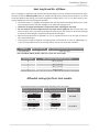
Check the elevation where your water heater is installed. Set DIPswitches shown in the table below
dependingonthealtitude.
Indoor models
DIPswitches
Altitude
0 (DEFAULT)
1
O N
2
3
4
5 6
7
8
9 1 0
O F F
110U(T-KJr2U)and
310(T-K4U)models
Up to 2,500 ft Up to 5,000 ft Up to 7,500 ft Over 7,500 ft
1
O N
3
4
5 6
7
8
9 1 0
O F F
1
O N
2
3
4 5 6
O F F
1
O N
2
3
4
5 6
7
8
9 1 0
O F F
No.3:OFF
No.4:OFF
No.5:OFF
510U(T-D2U)models
(Lower bank of
DIPswitches)
2
1
2
3
No.3:OFF
No.4:OFF
No.5:ON
4 5 6
1
O N
O F F
3
4
5 6
7
8
9 1 0
2
3
No.3:OFF
No.4:ON
No.5:ON
4 5 6
O F F
No.2:OFF
No.3:OFF
No.4:OFF
2
O F F
No.3:OFF
No.4:ON
No.5:OFF
O N
1
O N
1
O N
2
3
4 5 6
No.2:OFF
No.3:ON
No.4:OFF
O F F
No.2:OFF
No.3:OFF
No.4:ON
Consultour
Technical
Services
at1-888479-8324
No.2:OFF
No.3:ON
No.4:ON
Outdoor models
DIPswitches
Altitude
0 (DEFAULT)
O N
110U(T-KJr2U)and
310(T-K4U)models
2
3
4
5 6
7
8
9 1 0
O F F
O N
1
2
3
4
5 6
7
8
9 1 0
O F F
No.3:OFF
No.4:OFF
No.5:OFF
O N
510U(T-D2U)models
(Lower bank of
DIPswitches)
1
Up to 2,000 ft Up to 4,000 ft Up to 6,000 ft Over 6,000 ft
1
2
3
4 5 6
O F F
No.3:OFF
No.4:ON
No.5:OFF
O N
1
2
3
4
5 6
7
8
9 1 0
O F F
1
2
3
O N
O N
1
2
3
4 5 6
O F F
No.2:OFF
No.3:ON
No.4:OFF
1
2
3
4
5 6
7
8
9 1 0
O F F
No.3:OFF
No.4:OFF
No.5:ON
4 5 6
O F F
No.2:OFF
No.3:OFF
No.4:OFF
O N
No.3:ON
No.4:OFF
No.5:ON
O N
1
2
3
4 5 6
O F F
No.2:OFF
No.3:OFF
No.4:ON
Consultour
Technical
Services
at1-888479-8324
No.2:ON
No.3:OFF
No.4:ON
NOTE: ThedarksquaresindicatethedirectiontheDIPswitchesshouldbesetto.
110U (T-KJr2U) and 310U (T-K4U) models
Computer board
510U (T-D2U) models
Computer board
DIPswitches(Lowerbank)
DIPswitches
WARNING
DO NOT adjust any DIPswitches on the upper bank for the 510U (T-D2U)
models.
12
Page
Installation Manual
Installation
VENTING INSTRUCTIONS
For indoor models
-General• Improper venting of this appliance can result in excessive levels of carbon
monoxidewhichcanresultinseverepersonalinjuryordeath.
• Improperinstallationcancausenauseaorasphyxiation,severeinjuryordeath
fromcarbonmonoxideandfluegasespoisoning.Improperinstallationwillvoid
DANGER
productwarranty.
Wheninstallingtheventsystem,allapplicablenationalandlocalcodesmustbe
followed. If you install thimbles, fire stops or other protective devices and they
penetrateanycombustibleornoncombustibleconstruction,besuretofollowall
CAUTION applicablenationalandlocalcodes.
Thewaterheatermustbeventedinaccordancewiththesection“VentingofEquipment"ofthelatest
editionoftheNationalFuelGasCode:ANSIZ223.1/NFPA54intheUnitedStatesand/orSection7ofthe
CAN/CSAB149.1NaturalGasInstallationCodeinCanada,aswellasapplicablelocalbuildingcodes.
The manufacturer recommends the “T-Vent” line manufactured by TAKAGI(Referto“T-Vent”brochure
for details). However, the following are also UL listed manufacturers: ProTech Systems Inc. (FasNSeal),
Flex-LInc.,Z-FlexInc.(Z-VentIII),Metal-FabInc.,andHeat-FabInc.(Saf-TVent).
General rules for venting water heaters are:
• Placethewaterheaterascloseaspossibletotheventterminator.
• Theventcollarofthewaterheatermustbefasteneddirectlytoanunobstructedventpipe.
• Donotweldtheventpipetothewaterheater’sventcollar.
• Donotcuttheventcollaroftheunit.
• The vent must be easily removable from the top of the water heater for normal service and
inspectionoftheunit.
• Thewaterheaterventmustnotbeconnectedtoanyothergasapplianceorventstack.
• Avoidusinganoversizedventpipeorusingextremelylongrunsofthepipe.
• For rooftop venting, a rain cap or other form of termination that prevents rain water from
enteringintothewaterheatermustbeinstalled.
• Donotcommonventorconnectanyventfromotherappliancestothewaterheatervent.
General rules for vent terminations:
• Avoidlocatingthewaterheaterventterminatornearany air intake devices.Thesefanscanpick
uptheexhaustflueproductsfromthewaterheaterandreturnthemtothebuilding.Thiscan
createahealthhazard.
• Locatetheventterminatorsothatitcannotbeblockedbyanydebris,atanytime.Mostcodes
requirethattheterminatormustbeatleast12in.(305mm)abovegrade,buttheinstallermay
determineifitshouldbehigherdependingonthejobsiteconditionandapplicablecodes.
• A proper sidewall terminator is recommended when the water heater is vented through a
sidewall.
• Regardingtheclearancesfromtheexhaustterminatortotheairinletoropening,refertothe
nextfewpages.
13
Page
Installation Manual
Installation
-Vent length and No. of ElbowThisisaCategoryIIIapplianceandmustbeventedaccordingly.Theventsystemmustbesealedairtight.
Allseamsandjointswithout gaskets mustbesealedwithhighheatresistantsiliconesealantorULlisted
aluminumadhesivetapehavingaminimumtemperatureratingof350°F(177°C).Forbestresults,avent
systemshouldbeasshortandstraightaspossible.
• ThiswaterheaterisaCategoryIIIapplianceandmustbeventedaccordinglywithany4in.(102
mm)ventapprovedforusewithCategoryIIIorSpecialBHtypegasvent.
• Follow the vent pipe manufacturer’s instructions when installing the vent pipe.
• Do not common vent this appliance with any other vented appliance(Donotterminatevent
intoachimney.Iftheventmustgothroughthechimney,theventmustrunallthewaythrough
thechimneywithCategoryIIIapprovedorSpecialBHventpipe).
• Whenthehorizontalventrunexceeds5ft.(1.5m),supporttheventrunat3ft.(0.9m)intervals
withoverheadhangers.
• The maximum length of exhaust vent piping must not exceed 50 ft. (15.2 m) (deducting 5 ft.
(1.5m)foreachelbowusedintheventingsystem).Donotusemorethan5elbows.
Diameter
Max. No. of Elbow Max. Vertical and Horizontal (Total) Vent Length
4in.(102mm)
5
50ft.(15.2m)
*For each elbow added, deduct 1.5m (5 ft.) from max. vent length.
No. of Elbows
0
1
2
5
Max. Vertical or Horizontal Vent Length
50ft.(15.2m)
45ft.(13.7m)
40ft.(12.2m)
25ft.(7.6m)
Excludeselbowtermination,raincaps,orthe4in.(102mm)PVCConcentricTermination
-DIPswitch settings for Direct Vent modelsSetDIPswitchesshowninthetablebelowdependingontheventlength.
110U Direct vent (T-KJr2U-IN) 510U Direct vent (T-D2U-IN)
310 Direct vent (T-K4U-IN) (Upper bank of DIPswitches)
O N
1 2 3 4 56 7 8 9 1 0
1 2 3 4 56 7 8
O N
O F F
O F F
No.6:ON
No.7:OFF
O N
No.3:ON
No.4:OFF
1 2 3 4 56 7 8 9 1 0
O F F
O F F
No.3:ON
No.4:ON
14
0 to 30 ft
1 2 3 4 56 7 8
O N
No.6:ON
No.7:ON
Vent length
Page
31 to 50 ft
Installation Manual
Installation
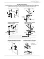
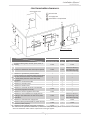
-Venting Illustrations-
For the 110U Indoor (T-KJr2U-IN), 310U Indoor (T-K4U-IN) and 510U Indoor (T-D2U-IN) models
Fordetailsoftheop